Table of Contents
Advertisement
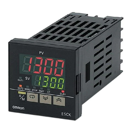
Ramp/Soak Process Controller
Advanced, 1/16-DIN Ramp/Soak
Process Controllers Ideal for
Worldwide Use
H
Offers one pattern of simple
programming control, up to four patterns
with communications (16 steps per
pattern)
H
Water-resistant front face meets
IP66/NEMA 4 (indoor use)
H
Modular structure, one-stock type
H
Heat/Cool control
H
Serial communications (RS-232C and
RS-485)
H
Temperature and analog inputs
H
High-accuracy: 100 ms sampling (for
analog input)
H
Conforms to international EMC and
safety standards
H
24V AC/DC type also available
H
3-year warranty
Ordering Information
Order control output boards and option boards separately. A single output board and option board can be mounted to each base unit. For
example, for a relay control output, order the E53-R4 output board in addition to the E5CK-TAA1-500 Process Controller.
J PROCESS CONTROLLERS
Description
Base unit with terminal cover
R
DIN size
1/16 DIN
(48 x 48 mm)
Supply voltage
Part number
100-240 VAC
E5CK-TAA1-500 AC100-240
24 VAC/VDC
E5CK-TAA1-500 AC/DC24
E5CK-T
RC
169
Advertisement
Table of Contents

Related Manuals for Omron E5CK-T


Summary of Contents for Omron E5CK-T
- Page 1 Ramp/Soak Process Controller E5CK-T Advanced, 1/16-DIN Ramp/Soak Process Controllers Ideal for Worldwide Use Offers one pattern of simple programming control, up to four patterns with communications (16 steps per pattern) Water-resistant front face meets IP66/NEMA 4 (indoor use) Modular structure, one-stock type...
-
Page 2: Temperature Ranges
E5CK-T E5CK-T J OPTIONAL OUTPUT BOARDS Description Specifications Compatible controller Max. quantity Part number Relay/Relay SPST/SPST, 5 A, 250 VAC E5CK-T E53-R4R4 Relay/Pulse SPST, 5 A/NPN, 24 VDC E5CK E53-Q4R4 SPST, 5 A/PNP, 24 VDC E5CK E53-Q4HR4 Relay/Linear current SPST, 5 A/4–20 mA... -
Page 3: Specifications
E5CK-T E5CK-T Specifications J RATINGS Model E5CK-T (Standard) E5CK-T (24 V Type) Supply voltage 100 to 240 VAC, 50/60 Hz 24 VAC/VDC, 50/60 Hz Power consumption 15 VA 6 VA, 3.5 W Operating voltage range 85% to 110% of rated supply voltage... - Page 4 E5CK-T E5CK-T Characteristics Table – continued from previous page Vibration resistance Malfunction: 10 to 55 Hz, 10 m/s (approx. 1G) for 10 min each in X, Y, and Z directions Destruction: 10 to 55 Hz, 20 m/s (approx. 2G) for 2 hrs each in X, Y, and Z directions...
-
Page 5: Operation
E5CK-T E5CK-T Nomenclature J E5CK-T Display 1 Display 2 Operation Indicators Up Key/Down Key Display Key RUN/RST Key Operation Note: Before changing any switch settings, always turn OFF the power supply to the Process Controller J SETTINGS 1. On a standard model, set up the output boards for control outputs 1 and 2 before mounting the Controller. - Page 6 E5CK-T E5CK-T Dimensions Unit: mm (inch) J E5CK-T Panel Cutouts 13.3 (0.52) 58 (2.28) (2.56) min. 53L x 53W 100 (3.94) (2.36) min. J ACCESSORIES (ORDER SEPARATELY) Terminal Cover E53-COV07 44.3 (1.74) (0.06) 44.3 (1.74)
-
Page 7: Installation
E5CK-T E5CK-T Installation J INSTALLATION J SETTING UP THE OUTPUT BOARD 1. Two rectangular holes are provided on the power board (right Main Parts side of Controller). Fit the two protrusions of the output board into these two holes. Termi- 2. -
Page 8: Terminal Cover
E5CK-T E5CK-T J MOUNTING THE CONTROLLER 1. Insert the Controller into the panel’s mounting hole at the position shown in the figure below. 2. Push the adapter along the Controller body from the terminals up to the panel, and fasten temporarily. -
Page 9: Terminal Arrangement
Power Blocks for E5CK–T The E5CK-T has independent power supplies for each of the terminal blocks shown below. Note: The power supplies for blocks C (exclude relay output) and D are shared for the following option board:... -
Page 10: Power Supply
E5CK-T E5CK-T J E5CK-T WIRING Power Supply Input 100 to 240 VAC or AC/DC 24 V to terminal numbers 4 and 5 according to the specification. Input Connect the input to terminal numbers 6 to 8 as follows according to the input type. -
Page 11: Auxiliary Output
E5CK-T E5CK-T Specifications for Each Type of Output Output type Specifications Relay 3 A at 250 VAC Voltage (NPN) 20 mA at 12 VDC (with short-circuit protection) Voltage (PNP) 20 mA at 12 VDC (with short-circuit protection) 0 to 10 V 0 to 10 VDC, permissible load impedance: 1 kΩ... -
Page 12: Quick Setup Instructions
Step 0: Set target value 9. When the target value and time settings are com- Target value (default setting: 0) plete, press the Display Key. Note: For more details about programming refer to the E5CK-T Display key User’s Manual, H090-E3-1. - Page 13 E5CK-T E5CK-T J AFTER TURNING POWER ON J INPUT TYPE Determine the I/O specifications of the Process Controller in setup Set the code according to the following table. Default is mode. “2: K1 thermocouple.” Power ON Platinum Resistance Thermometer Input type...
- Page 14 (heat), control output (cool), alarm 1, alarm 2, alarm 3, LBA. The auxiliary outputs of the Process Controller cannot be used as control outputs. The E5CK-T does not have a heater burnout alarm (HBA). Control output (heat), control output (cool), alarm 1, alarm 2, alarm 3, LBA, error 1 (input error), and error 2 (A/D converter error) output functions are available.
-
Page 15: Deviation Alarm
E5CK-T E5CK-T J ALARM MODE SELECTORS Alarm outputs are available if they are allocated as outputs. Factory setting is “2: Upper-limit alarm (deviation).” Alarm operation Alarm output Switch setting When X is positive When X is negative Upper- and lower-limit alarm (deviation) - Page 16 E5CK-T E5CK-T J CLOSE IN ALARM/OPEN IN ALARM When the Controller is set to “close in alarm,” the status of the alarm output function is output as it is. When set to “open in alarm,” the status of the alarm output function is output inverted.
- Page 17 E5CK-T E5CK-T J PARAMETERS AND MENUS All functions selected with the Controller in setup or expansion mode or all optional functions of the Process Controller may not be displayed. Note: All references to Heater Burnout Alarm Function and “position-proportional” apply only to E5EK/AK-T and are not applicable to E5CK-T.
- Page 18 E5CK-T E5CK-T J PARAMETER OPERATION J PROTECT MODE Refer to “Settings” in the Operation Section. RUN/RST Press twice Level 0 Mode for 1 s min. Security Measured value Process Value Set Point Key protect RUN/RST Pattern Number To level 0 (With E5CK–T, this display appears when more...
- Page 19 E5CK-T E5CK-T J LEVEL 1 MODE AT Execute/Cancel Proportional Band Available if the Controller is in advanced PID control. Integral Time Available if the Controller is in advanced PID control. Derivative Time Available if the Controller is in advanced PID control.
-
Page 20: Input Shift
E5CK-T E5CK-T J LEVEL 2 MODE Input Shift When temperature input is selected, scaling is not required. This is because input is treated as the “temperature” as it is Remote/Local Used for the matched to the input type. However, note that the upper- and communications function. - Page 21 Set when the transfer output function is being used. Alarm Valid During Ramping Transfer Output Lower Limit Set when the transfer output function is being used. Run-all Valid (with E5CK-T, this display appears when more than two patterns are used.) For E5jK-TPRR2 (not on E5CK-T) α...
- Page 22 E5CK-T E5CK-T J PROGRAM MODE Pattern number Synchronized with the pattern number of level 0 mode. Step number Refer to the Changed to the ramp setting method. Operation Manual for the ramp setting method. Target value 0 Time setting method...
- Page 23 E5CK-T E5CK-T Number of patterns executed Alarm value 1 (displayed only if the alarm is allocated) Alarm value 2 (displayed only if the Time Signal alarm is allocated) Two types of time signal patterns can be set in each pattern.
- Page 24 E5CK-T E5CK-T J HOW TO USE THE ERROR DISPLAY When an error has occurred, the No.1 display alternately indicates error codes together with the current display item. This section describes how to check error codes on the display, and the actions that must be taken to remedy the problem.
-
Page 25: Display Range Over
E5CK-T E5CK-T Display Range Over Meaning Though not an error, this is displayed when the process value exceeds the display range when the control range (setting range ±10%) is larger than the display range (–1999 to 9999). • When less than “–1999”... - Page 26 E5CK-T E5CK-T Precautions J OPERATING ENVIRONMENT J OPERATION • • Operate the Controller within the rated ambient operating The alarm outputs of a model with an alarm function may not temperature, ambient operating humidity, and storage tem- turn ON correctly when the model malfunctions. The use of perature ranges.
- Page 27 E5AK-/E5EK-T: E5AK-/E5EK-T: E5AK-/E5EK-T: 2 pcs. E5AK-/E5EK-T: 5 pcs. connected 8 pcs. 8 pcs. 5 pcs. E5CK-T: 1 piece E5CK-T: 2 pcs. in parallel E5CK-T: 4 pcs. E5CK-T: 4 pcs. E5CK-T: 2 pcs. Rated 5 to 24 VDC 5 to 24 VDC...
- Page 28 E5CK-T E5CK-T OMRON ELECTRONICS, INC. OMRON CANADA, INC. One East Commerce Drive 885 Milner Avenue Schaumburg, IL 60173 Scarborough, Ontario M1B 5V8 1-800-55-OMRON 416-286-6465 Cat. No. GCTC13 8/00 Specifications subject to change without notice. Printed in U.S.A.
Need help?
Do you have a question about the E5CK-T and is the answer not in the manual?
Questions and answers