Table of Contents
Advertisement
Quick Links
Advertisement
Table of Contents

Related Manuals for Kontron speedMOPSlcdCE


Summary of Contents for Kontron speedMOPSlcdCE
- Page 1 User’s Guide Document Revision 1.2...
-
Page 3: Table Of Contents
5. CPU, CHIPSET AND SUPER I/O ................14 CPU......................14 Chipset ...................... 15 5.2.1. GMCH (815E Chipset) ................15 5.2.2. ICH4 (82801DB)..................16 Super I/O ....................17 CPU, Chipset and Super-I/O Configuration............17 6. SYSTEM MEMORY ....................18 7. ISA AND PCI BUS EXPANSION.................19 speedMOPSlcdCE User’s Guide Contents... - Page 4 12.2 Configuration....................31 13. USB INTERFACES ....................32 13.1 Connector ....................32 13.1.1. Limitations ..................32 13.2 Configuration....................33 14. FLOPPY INTERFACE ....................34 14.1 Connector ....................34 14.1.1. Connector Diagram ................35 14.2 Configuration....................35 15. IDE INTERFACES ....................36 Contents speedMOPSlcdCE User’s Guide...
- Page 5 Using Expanded Memory Managers ............52 23.4 I/O Address Map ..................53 23.5 Peripheral Component Interconnect (PCI) Devices..........54 23.6 SM Bus Devices .................... 54 24. APPENDIX B: BIOS OPERATION ................55 24.1 Determining the BIOS Version................. 55 speedMOPSlcdCE User’s Guide Contents...
- Page 6 24.7 Boot Menu and Utilities ................. 71 24.7.1. MultiBoot XP ..................71 24.7.2. Boot First Function ................72 24.8 Exit Menu ....................73 24.9 Kontron BIOS Extensions ................74 24.9.1. JIDA BIOS extension ................74 Remote Control Client Extension ............. 74 24.9.2. 24.9.3.
- Page 7 28.1.2. PC/104, PCI..................88 28.2 General PC Architecture ................. 89 28.3 Ports ......................89 28.3.1. RS-232 Serial..................89 28.3.2. ATA ....................90 28.3.3. USB ....................90 28.4 Programming ....................90 29. APPENDIX G: DOCUMENT REVISION HISTORY.............91 speedMOPSlcdCE User’s Guide Contents...
- Page 8 KONTRON Contents speedMOPSlcdCE User’s Guide...
-
Page 9: User Information
“as-is” and is subject to change without notice. For the circuits, descriptions and tables indicated, KONTRON assumes no responsibility as far as patents or other rights of third parties are concerned. -
Page 10: Trademarks
KONTRON Embedded Modules will not be responsible for any defects or damages to other products not supplied by KONTRON Embedded Modules that are caused by a faulty KONTRON Embedded Modules product. -
Page 11: Technical Support
We are committed to making our product easy to use and will help you use our products in your systems. Before contacting KONTRON Embedded Modules technical support, please consult our Web site for the latest product documentation, utilities, and drivers. If the information does not help solve the problem, contact us by telephone. -
Page 12: Introduction
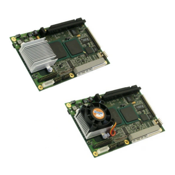
KONTRON INTRODUCTION speedMOPSlcdCE The speedMOPSlcdCE hosts either an ULV Intel® Celeron® processor or an LV Intel® Celeron® ® processor in combination with an Intel 815E chipset that includes an integrated graphics memory-controller hub. A SDRAM-SODIMM socket can hold either PC100 or PC133 SODIMM memory modules up to 512MB. - Page 13 The speedMOPS line products support the PC/104-Plus (PCI) and the PC/104 (ISA) standard via Kontron’s own PCI-to-ISA bridge. Because of the availability of both extension buses, all past and future PC/104 expansion assemblies with state-of-the-art processor performance can be accommodated.
-
Page 14: Getting Started
KONTRON GETTING STARTED The easiest way to get the speedMOPSlcdCE board running is to use a starter kit from Kontron Embedded Modules GmbH. Take the following steps: 1. Turn off the power supply (part of the starter kit). 2. Connect the power supply to the starter kit baseboard (part of the starter kit). -
Page 15: Specifications
Enhanced Parallel Port (EPP) and Extended Capabilities Port (ECP) with bi-directional capability Floppy Interface Enhanced Intelligent Drive Electronics (EIDE) Two Peripheral Component Interconnect (PCI) Bus Master IDE ports (up to 4 devices) speedMOPSlcdCE User’s Guide Specifications... - Page 16 Windows Sound System™compatible Phoenix BIOS, 1024KB Flash BIOS NV-EEPROM for CMOS Setup Retention without Battery PS/2 Keyboard Controller PS/2 Mouse Controller Watchdog Timer (WDT) Real Time Clock (RTC) with Onboard Battery Supply Specifications speedMOPSlcdCE User’s Guide...
-
Page 17: Mechanical Specifications
4.2.2. One 4 x 30 pin 2mm stackthrough connector The PC/104plus connector does not have a connector shroud. This mechanical limitation does not reduce the functionality of a speedMOPSlcdCE board. Dimensions 4.2.3. Length x Width: 96mm x 147mm (3,8" x 5,8") Height on Top 4.2.4. -
Page 18: Electrical Specifications
Supply Current (typical) 4.3.3. The speedMOPSlcdCE is equipped with power-saving features. Different power-consumption tests were executed to give an overview of the electrical conditions for several operational states. The board used a 256MB SDRAM module for test results shown below. An attached hard disk was not supplied through the measurement path, and there was no extension module in the system. -
Page 19: Supply Current (Maximum)
3.79A speedMOPSlcdCE 733MHz 4.81A speedMOPSlcdCE 1GHz 5.61A (Calculated theoretical values from all components maximum supply currents) Real-time Clock (RTC) Battery 4.3.5. Voltage range: 2.0 - 4.0V (typ 3.0V) Quiescent current: max. 3,5uA@ 3.0 V speedMOPSlcdCE User’s Guide Specifications... -
Page 20: Mtbf
(extreme altitude, vibration, and salt water exposure) will lower the MTBF values. System MTBF (hours) : 184220 Notes: Fans shipped with Kontron Embedded Modules GmbH products have an operating life of up to 50,000 hours. The estimates above assumed that a passive heat-sinking arrangement was used instead of a fan. -
Page 21: Environmental Specifications
Note: (*) The maximum operating temperature is the maximum measurable temperature on any spot on the module’s surface. You must maintain the temperature according to the above specification. Humidity 4.5.2. Operating: 10% to 90% (non-condensing) Non-operating: 5% to 95% (non-condensing) speedMOPSlcdCE User’s Guide Specifications... -
Page 22: Cpu, Chipset And Super I/O
KONTRON CPU, CHIPSET AND SUPER I/O ® ® The speedMOPSlcdCE is available with an Intel LV/ULV Celeron central processing unit (CPU) at speeds of either 400MHz or 733MHz. ® Intel LV/ULV Celeron CPU features include: Support for the Intel Architecture with Dynamic Execution ... -
Page 23: Chipset
KONTRON Chipset ® The chipset of the speedMOPSlcdCE consists of the Intel 815E chipset GMCH (Graphics and Memory ® Controller Hub) and the Intel 82801DB ICH-4 (I/O Controller Hub 4). GMCH (815E Chipset) 5.2.1. Processor/Host Bus Support Intel® Pentium® III processor and Intel® Celeron®... -
Page 24: Ich4 (82801Db)
Supports DMA collection buffers Timers based on 82C54 Power-Management Logic APM compliant Supports PCI PME# Low Pin Count (LPC) interface SM (System Management) Bus 2.0 interface CPU, Chipset and Super I/O speedMOPSlcdCE User’s Guide... -
Page 25: Super I/O
Floppy Disk Controller PS/2-Keyboard and PS/2-Mouse Interface CPU, Chipset and Super-I/O Configuration See the Advanced Menu and its submenus section in the Appendix B: BIOS chapter for information on setting choices. speedMOPSlcdCE User’s Guide CPU, Chipset and Super I/O... -
Page 26: System Memory
KONTRON SYSTEM MEMORY The speedMOPSlcdCE uses a 144-pin Small Outline-Dual Inline Memory Modules (SODIMM) on the bottom side of the board. One socket is available for 3.3 Volt (power level) un-buffered PC-133 or PC-100 Synchronous Dynamic Random Access Memory (SDRAM) of 8, 16, 32, 64, 128, 256 or 512MB. -
Page 27: Isa And Pci Bus Expansion
PC/104 Connectors 7.1.1. The speedMOPSlcdCE features the XT bus and AT bus extension on two, dual-row socket connectors with a 2.54mm x 2.54mm grid (0.1" x 0.1"). The PC-104 bus is available through Connectors J6B and J6C. To find the location of the connectors see the Appendix E: Connector Layout chapter. -
Page 28: Pc/104 Configuration
PC/104-Plus Connector 7.2.1. You can use PC/104-Plus adapter boards on the top and on the bottom of a speedMOPSlcdCE’s stackthrough connector. The PC/104plus connector does not have a connector shroud. If you intend to use +3.3V powered PC/104plus adapter cards, the +3.3V has to be supplied separately because it is not generated onboard the speedMOPSlcdCE. -
Page 29: Graphics Interfaces
GRAPHICS INTERFACES Video Controller The speedMOPSlcdCE uses the graphics accelerator integrated in the Intel® 815E chipset. It delivers high performance 2D, 3D and video capabilities. With its interface to UMA (Unified Memory Architecture), up to 1MB of legacy system memory is used as video memory. The video memory can be extended to 32MB by the use of the available “Intel®... -
Page 30: Flat Panel Lvds Interface (Jili) Connector
–30V to +30V. Backlight converters usually are +5V or +12V types. When using a Kontron JILI cable, you do not need to determine the configuration. Display logic voltage and contrast voltage come pre-configured on the JILI cable. On occasion, the backlight voltage has to be adjusted on the cable. -
Page 31: Connecting A Lcd Panel
We regularly update the list of panels that have been tested with our boards. Many panel adapters for a wide spread variety of displays are available through Kontron. If you use one of those adapters supplied by Kontron, configuration is easy: 1. -
Page 32: Available Video Modes
Text 132x50 10Ch Text 132x60 10Eh Graphics 320x200 110h Graphics 640x480 111h Graphics 640x480 112h Graphics 640x480 113h Graphics 800x600 114h Graphics 800x600 11Ch Text 128x37 11Dh Graphics 320x200 127h Graphics 640x400 128h Graphics 640x400 Graphic Interfaces speedMOPSlcdCE User’s Guide... -
Page 33: Serial-Communication Interfaces
To have the signals available on the standard serial interface connectors DSUB9 or DSUB25, an adapter cable is required. A 9-pin DSUB cable is available from Kontron (KAB-DSUB9-2, Part Number 96017-0000-00-0). The following table shows the pinouts for COMA and COMB, as well as necessary connections for DSUB adapters. -
Page 34: Parallel-Port Interface
KONTRON PARALLEL-PORT INTERFACE The speedMOPSlcdCE incorporates a parallel port that can be set to uni-directional and supports EPP and ECP operating modes. Connector 10.1 The parallel port is available through the X6 connector (26 pins). To have the signals available on a standard, parallel-interface connector DSUB-25, an adapter cable is required, which is offered by Kontron (KAB-DSUB25-1, Part Number 96015-0000-00-0). -
Page 35: Configuration
IRQ5 or IRQ7 as the parallel-port interrupt. In ECP mode, you can choose DMA 1 or DMA 3. Refer to the I/O Device Configuration Submenu in the Appendix B: BIOS Operation chapter for additional information on configuration. speedMOPSlcdCE User’s Guide Parallel Port Interface... -
Page 36: Keyboard And Feature Interface
KONTRON KEYBOARD AND FEATURE INTERFACE The keyboard and feature connector of the speedMOPSlcdCE offers five functions. The interface connects the following: Keyboard Keyboard lock switch Speaker Battery Reset button Connector 11.1 The keyboard and feature connector is available through Connector J12 (10 pins). An adapter cable is required to connect a standard keyboard to this interface. -
Page 37: Signal Descriptions
KBDAT (Keyboard Data) Bi-directional I/O pin on CPU modules Keyboard data signal KBCLK (Keyboard Clock) Bi-directional I/O pin on CPU modules Keyboard clock signal speedMOPSlcdCE User’s Guide Keyboard and Feature Interface... -
Page 38: Configuration
FEMALE (Speaker) (KBCLK) (GND) (KBDAT) (+5V Vcc) (PWRGOOD) (/RESIN) (/KBLOCK) (BATT) Configuration 11.3 Refer to the Keyboard Features submenu in the Appendix B: BIOS chapter for information on configuration of the keyboard interface. Keyboard and Feature Interface speedMOPSlcdCE User’s Guide... -
Page 39: Ps/2 Mouse Interface
12.1 The PS/2 mouse interface is available on Connector J11 (4 pins). An adapter cable is required to connect a standard PS/2 mouse. The cable is available from Kontron (KAB-MOUSE-PS2, Part Number 96062-0000-00-0). The following table shows the pinout and connections for a PS/2 mouse adapter. -
Page 40: Usb Interfaces
KONTRON USB INTERFACES The speedMOPSlcdCE comes with two USB 2.0 ports, which you can expand by adding external hubs. You can connect up to 127 USB peripherals. Connector 13.1 The USB ports are available through the J17 and the J18 connectors (4 pins) each. To find the location of the USB ports on the speedMOPSlcdCE board, please see the Appendix E: Connector Layout chapter. -
Page 41: Configuration
You can download available drivers or get driver download support information from the Kontron Web site. Kontron offers the latest Kontron-tested drivers, which can differ from newer ones. For further technical questions, contact your local support or get support information and downloadable software updates from Intel®. -
Page 42: Floppy Interface
(ADA-FLOPPY-2, Part Number 96001-0000-00-0). If you have a slim-line 3.5” floppy drive, you may need a flat foil cable (KAB-FLOPPY/MOPS-1, Part Number 96019-0000-00-0). It also is possible to get a slim line 3.5” floppy drive with cable from Kontron (FLOPPY-MOPS-1, Part Number 96010-0000-00-0). -
Page 43: Connector Diagram
Refer to the Main Menu and the Miscellaneous Menu section of the Appendix B: BIOS Operation chapter for more information on configuring the floppy drive. You also can disable the floppy-disk interface in the I/O Device Configuration Submenu. speedMOPSlcdCE User’s Guide Floppy Interface... -
Page 44: Ide Interfaces
Number 96021-0000-00-0) or a 3.5” form factor (KAB-IDE-25, Part Number 96020-0000-00-0). You can plug a Kontron chipDISK, which is an IDE hard disk that uses Flash technology, into the IDE interface. You also can use a chipDISK adapter (chipDISK-ADA1, Part Number 96004-0000-00-0) or compact Flash adapter (CFC-ADA1, Part Number 96004-0000-00-2) for more disk support. -
Page 45: Configuration
-- the wires have the right diameter to withstand the maximum available current -- the enclosure of the peripheral device fulfils the fire-protecting requirements of -- IEC/EN 60950. To find the location of IDE-controller interfaces on the speedMOPSlcdCE board, please see the Appendix E: Connector Layout chapter. Configuration 15.2... -
Page 46: Ethernet Interfaces
KONTRON ETHERNET INTERFACES The speedMOPSlcdCE can come with two Ethernet interfaces. However the second Ethernet interface is optional and not equipped on every version of this product. The first Ethernet interface uses the ICH4’s integrated 32-bit PCI LAN controller in combination with the Intel® 82562 platform LAN connect device. -
Page 47: Second Ethernet Controller (Optional)
Digital clock recovery circuit using advanced digital algorithm to reduce jitter High-performance 100Mbps clock generator and data-recovery circuit Loopback mode for easy system diagnostic Note: The Ethernet interface works according to the common criteria of the embedded technology market segment. speedMOPSlcdCE User’s Guide Ethernet Interfaces... -
Page 48: Connectors
Ethernet Technical Support 16.5 You can solve some problems by using the latest drivers for both LAN controllers. Kontron provides you with the latest Kontron-tested drivers, which can differ from newer ones. For further technical support, contact either Kontron or get support information and downloadable software updates from Intel®... -
Page 49: Sound Interface
KONTRON SOUND INTERFACE The speedMOPSlcdCE uses a Realtek ALC650 sound codec. The ALC650 is an 18-bit, full duplex AC’97 2.2 compatible stereo audio CODEC designed for PC multimedia systems, including host/soft audio and AMR/CNR based designs. The ALC650 incorporates proprietary converter technology to achieve a high SNR, greater than 90 dB. -
Page 50: Connector
DMA-channels are possible. Refer to the Appendix B: BIOS operation for more details You can download available drivers for the sound controller from the Kontron Web site or use the drivers provided by the manufacturer Realtek. Search for ALC650 drivers for the required operating system. -
Page 51: Fan Interface
-- the wires have the right diameter to withstand the maximum available current -- the enclosure of the peripheral device fulfils the fire-protecting requirements of -- IEC/EN 60950. Configuration 18.2 You do not need to configure this feature. speedMOPSlcdCE User’s Guide Fan Interface... -
Page 52: Power Interface
KONTRON POWER INTERFACE In some applications, the speedMOPSlcdCE is intended for use as a stand-alone module without a backplane. You need to have a power connector available on the board for direct power supply. The speedMOPSlcdCE is a +5V-only board. Peripherals can obtain additional voltage from the power connectors next to the PC/104 bus. -
Page 53: Power Pins
Every power pin on the two power connectors as well as on the PC/104 bus connectors is limited to a maximum current of 1A per pin. If a system using a speedMOPSlcdCE is only supplied from the two power connectors, the following limitations apply:... -
Page 54: External Battery
You can connect an external battery to Pin 3 (BATT) of the power connector instead of Pin 9 of the keyboard connector. For more information refer to the Keyboard and Feature Interface section. Note: The two battery inputs are protected against each other by diodes. Power Interface speedMOPSlcdCE User’s Guide... -
Page 55: Watchdog Timer
The watchdog timer (WDT) is integrated in the Winbond W83627HF controller of the speedMOPSlcdCE and can issue a reset to the system or generate a non-maskable interrupt (NMI). The watchdog timer circuit has to be triggered within a specified time by the application software. -
Page 56: Hardware Monitor
CPU die. For more information on this submenu, see the Appendix B: BIOS Operation chapter in this manual. To monitor the parameters of this feature from your operating system, Kontron recommends that you use the 32-bit protected mode JUMPtec’s Intelligent Device Architecture driver (JIDA 32) with the test and demo application for Windows 95/98/ME/NT/2000/XP, which is available on the KONTRON Web site. -
Page 57: Thermal Management
KONTRON THERMAL MANAGEMENT The Thermal Management feature of the speedMOPSlcdCE helps control the processor’s temperature by activating the automatic thermal throttling after the processor silicon reaches a certain temperature. This feature can be enabled and configured in the BIOS Setup utility. You can specify the temperature level when throttling starts, define a hysteresis value to get back to 100% CPU performance, and specify the percentage for CPU performance in throttling mode. -
Page 58: Appendix A: System-Resource Allocation
(1) If the „used for“-device is disabled in setup, the corresponding interrupt is available for other devices. (2) Possible setting for LPT1. IRQ7 is the default setting. (3) Used in Soundblaster compatibility mode. Appendix A: System Resource Allocations speedMOPSlcdCE User’s Guide... -
Page 59: Direct Memory Access (Dma) Channels
(2) Possible setting for LPT1 if configured for ECP mode. Memory Map 23.3 The speedMOPSlcdCE processor modules can support up to 512MB of memory. The first 640KB of SDRAM are used as main memory. Using DOS, you can address 1MB of memory directly. Memory area above 1MB (high memory, extended memory) is accessed under DOS via special drivers such as HIMEM.SYS and EMM386.EXE,... -
Page 60: Using Expanded Memory Managers
This is a bug of EMM386, not the speedMOPSlcdCE. Please read the technical manuals of add-on cards used with the speedMOPSlcdCE for the memory areas they use. If necessary, also exclude their memory locations to avoid a conflict with EMM386. -
Page 61: I/O Address Map
I/O Address Map 23.4 The I/O-port addresses of the speedMOPSlcdCE are functionally identical with a standard PC/AT. All addresses not mentioned in this table should be available. We recommend that you do not use I/O addresses below 0110hex with additional hardware for compatibility reasons, even if available. -
Page 62: Peripheral Component Interconnect (Pci) Devices
Intel chipset SM Bus Devices 23.6 The speedMOPSlcdCE uses an onboard SM (System Management) Bus. This bus is not available on an external connector. The following SM Bus addresses are already used on the speedMOPSlcdCE. SM Bus Address... -
Page 63: Appendix B: Bios Operation
KONTRON APPENDIX B: BIOS OPERATION The speedMOPSlcdCE comes with Phoenix BIOS 4.0, Release 6.1, which is located in the onboard Flash EEPROM in compressed from. The device has an 8-bit access. The shadow RAM feature offers faster access (16 bit). You can update the BIOS using a Flash utility. For complete Phoenix BIOS 4.0 information, visit the Phoenix Technologies Web site. -
Page 64: Configuring The System Bios
The Phoenix BIOS setup utility allows you to change system behavior by modifying the BIOS configuration. Setup-utility menus allow you to make changes and turn features on or off. BIOS setup menus represent those found in most models of the speedMOPSlcdCE. The BIOS setup utility for specific models can differ slightly. - Page 65 General Help Window Pressing <F1> or <ALT-F1> on a menu brings up the General Help window that describes the legend keys and their alternates. Press <Esc> to exit the General Help window. speedMOPSlcdCE User’s Guide Appendix B: BIOS Operation...
-
Page 66: Main Menu
Displays amount of extended memory detected during boot-up. Notes: In the Option column, bold shows default settings. Extended Memory = capacity of memory module – selected frame buffer memory size (Video boot type) Appendix B: BIOS Operation speedMOPSlcdCE User’s Guide... -
Page 67: Master Or Slave Submenus
Disabled Shows whether a disk supports SMART. Enabled Note: In the Option column, bold shows default settings. The board only supports up to UDMA33. This is a limitation from the 44pin IDE interfaces. speedMOPSlcdCE User’s Guide Appendix B: BIOS Operation... -
Page 68: Advanced Menu
UMA video memory Onboard Video 1MB to 512KByte or 1MB. Enable Memory gap Disabled Allows enabling a 1MB memory gap Extended for add-on cards at 15MB. Note: In the Option column, bold shows default settings. Appendix B: BIOS Operation speedMOPSlcdCE User’s Guide... -
Page 69: Pci/Pnp Configuration Submenu
Minimum guaranteed time slice C0h, E0h allocated for bus master in units of PCI bus clocks. A high-priority, high-throughput device may benefit from a greater value. Note: In the Option column, bold shows default settings. speedMOPSlcdCE User’s Guide Appendix B: BIOS Operation... -
Page 70: Pci/Pnp Isa Irq Resource Exclusion Submenu
In the Option column, bold shows default settings. IRQ9 is used for SCI in ACPI mode. Do not use IRQ9 for legacy ISA devices when ACPI enabled. (**) Entry is only visible when primary IDE or secondary IDE is disabled. Appendix B: BIOS Operation speedMOPSlcdCE User’s Guide... -
Page 71: Memory Cache Submenu
DC00 - DFFF Write Back Write Protect: Writes are ignored. Write Back: Writes are cached but not sent to main memory until necessary. Note: In the Option column, bold shows default settings. speedMOPSlcdCE User’s Guide Appendix B: BIOS Operation... -
Page 72: I/O Device Configuration Submenu
EHCI driver is loaded. (***) If you want to use the USB boot feature, enable USB BIOS Legacy Support. A 16kb UMB area (most likely DC000h-DFFFFh) is used for USB BIOS Legacy Support. Appendix B: BIOS Operation speedMOPSlcdCE User’s Guide... -
Page 73: Keyboard Features Submenu
Battery voltage CPU Temperature CPU Temperature in °C and °F CPU Fan Speed CPU fan speed in rpm, (not available until BIOS ”no function” will be displayed on boards with passive cooling revision P815R112) speedMOPSlcdCE User’s Guide Appendix B: BIOS Operation... -
Page 74: Watchdog Timer Settings Submenu
(***) Only visible if the panel adapter is equipped with a MAX5362 DAC for backlight control. (****) Only visible if the panel adapter is equipped with a Xicore X9429 digital potentiometer for contrast control. Appendix B: BIOS Operation speedMOPSlcdCE User’s Guide... -
Page 75: Miscellaneous Submenu
The graphical logo stays up until just before the OS loads unless: You press <Esc> to display the POST screen You press <F2> to enter Setup POST issues an error message The BIOS or an option ROM requests keyboard input speedMOPSlcdCE User’s Guide Appendix B: BIOS Operation... -
Page 76: Security Menu
In the Option column, bold shows default settings. Enabling Supervisor Password requires a password for entering Setup. Passwords are not case sensitive. User and Supervisor passwords are related. A User password is possible only if a Supervisor password exists. Appendix B: BIOS Operation speedMOPSlcdCE User’s Guide... -
Page 77: Power Menu
Last State in conjunction with a CMOS backup battery. Notes: In the Option column, bold indicates default setting. See the chapter “Thermal Management” of this user’s guide for more details about these features. speedMOPSlcdCE User’s Guide Appendix B: BIOS Operation... -
Page 78: Thermal Management Submenu
13%, 25%, 50%, 75% Specifies the throttling percentage of the CPU performance. Notes: In the Option column, bold indicates default setting. See the chapter “Thermal Management” of this user’s guide for more details about these features. Appendix B: BIOS Operation speedMOPSlcdCE User’s Guide... -
Page 79: Boot Menu And Utilities
KONTRON Boot Menu and Utilities 24.7 MultiBoot is a boot utility integrated in the PhoenixBIOS 4.0. The speedMOPSlcdCE provides the MultiBoot XP version with integrated Boot First function. MultiBoot XP 24.7.1. MultiBoot XP comes with a complete new look of the Boot Device Priority submenu. This submenu is now separated into two sections: ... -
Page 80: Boot First Function
Override the existing boot sequence (for this boot only) by selecting another boot device. If the specified device does not load the OS, the BIOS reverts to the previous boot sequence. Enter Setup. Press <Esc> to continue with the existing boot sequence. Appendix B: BIOS Operation speedMOPSlcdCE User’s Guide... -
Page 81: Exit Menu
CMOS, you can restore the values you saved to CMOS. Save Changes Saves all the selection without Save changes. exiting Setup. You can return to the other menus to review and change your selection. speedMOPSlcdCE User’s Guide Appendix B: BIOS Operation... -
Page 82: Kontron Bios Extensions
Kontron BIOS Extensions 24.9 Besides the Phoenix System BIOS, the speedMOPSlcdCE comes with a few BIOS extensions that support special features. All extensions are located in the onboard Flash EEPROM. Some extensions are permanently available; some are loaded if required during boot-up. Supported features include: ... -
Page 83: Lan Pxe Rom
Ethernet controller loads into memory during boot-up. This optional ROM allows you to boot the speedMOPSlcdCE over an Ethernet connection. A server with Intel PXE boot support is required on the other side of the Ethernet connection. The setup and configuration of the server, including PXE support, is not the responsibility of Kontron. -
Page 84: Updating Or Restoring Bios Using Phoenixphlash
24.10.1. Use the following procedure to update or restore the BIOS. 1. Download the Phoenix Phlash compressed file, CRDxP815.ZIP, from the KONTRON Embedded Modules Web site or contact your local technical support for it. The zip file contains the following:... -
Page 85: Preventing Problems When Updating Or Restoring Bios
For further information on the update key and the crisis diskette, see the Application Note PHLASH_SCE???, which is available from the KONTRON Embedded Modules Web site. The three question marks stand for the revision number of the file. -
Page 86: Appendix C: Block Diagram
KONTRON APPENDIX C: BLOCK DIAGRAM Appendix C: Block Diagram speedMOPSlcdCE User’s Guide... -
Page 87: Appendix D: Mechanical Dimensions
KONTRON APPENDIX D: MECHANICAL DIMENSIONS Board Dimensions and Mounting Holes 26.1 Top View 26.1.1. speedMOPSlcdCE User’s Guide Appendix D: Mechanical Dimensions... -
Page 88: Side View
KONTRON Side View 26.1.2. Appendix D: Mechanical Dimensions speedMOPSlcdCE User’s Guide... -
Page 89: Appendix E: Connector Layout
KONTRON APPENDIX E: CONNECTOR LAYOUT Top Side 27.1 Notes: The position of Pin 1 is marked with a quadratic pad on the PCB. speedMOPSlcdCE User’s Guide Appendix E: Connector Layout... -
Page 90: Bottom Side
KONTRON Bottom Side 27.2 Appendix E: Connector Layout speedMOPSlcdCE User’s Guide... -
Page 91: Connector Functions And Interface Cables
2.54mm 6 pos. KAB-SOUND-CMP Cable with open (JST XHP-6 (PN96063-0000-00-0) ends with crimp contacts JST SXH-001T-PO.6 JST SXH-002T-PO.6) LPT Connector 2.54mm 26 pos. KAB-DSUB25-1 For DSUB 25 (AMP 2-215882-6 or (PN 96015-0000-00-0) adaptation. compatible) speedMOPSlcdCE User’s Guide Appendix E: Connector Layout... -
Page 92: Pin-Out Table
To protect the external power lines of peripheral devices, make sure that: - the wires have the right diameter to withstand the maximum available current - the enclosure of the peripheral device fulfils the fire protecting requirements of - IEC/EN 60950. Appendix E: Connector Layout speedMOPSlcdCE User’s Guide... - Page 93 Reserved Reserved Notes : (**) Not generated onboard of the speedMOPSlcdCE (***) To protect the external power lines of peripheral devices, make sure that: - the wires have the right diameter to withstand the maximum available current - the enclosure of the peripheral device fulfils the fire protecting requirements of - IEC/EN 60950.
- Page 94 To protect the external power lines of peripheral devices, make sure that: - the wires have the right diameter to withstand the maximum available current - the enclosure of the peripheral device fulfils the fire protecting requirements of - IEC/EN 60950. Appendix E: Connector Layout speedMOPSlcdCE User’s Guide...
- Page 95 To protect the external power lines of peripheral devices, make sure that: - the wires have the right diameter to withstand the maximum available current - the enclosure of the peripheral device fulfils the fire protecting requirements of - IEC/EN 60950. speedMOPSlcdCE User’s Guide Appendix E: Connector Layout...
-
Page 96: Appendix F: Pc Architecture Information
PCI & PCI-X Hardware and Software Architecture & Design, Fifth Edition, Edward Solari and George Willse, Annabooks, 2001, ISBN 0-929392-63-9. PCI System Architecture, Tom Shanley and Don Anderson, Addison-Wesley, 2000, ISBN 0-201-30974-2. Appendix F: PC Architecture Information speedMOPSlcdCE User’s Guide... -
Page 97: General Pc Architecture
The Interface Data Book includes application notes. Type “232” as a search criteria to obtain a list of application notes. You can search for information about the data book on National Semiconductor’s Web site. speedMOPSlcdCE User’s Guide Appendix F: PC Architecture Information... -
Page 98: Ata
The Programmer’s PC Sourcebook, Second Edition, Thom Hogan, Microsoft Press, 1991, ISBN 1-55615-321-X Undocumented PC, A Programmer’s Guide to I/O, CPUs, and Fixed Memory Areas, Frank van Gilluwe, Second Edition, Addison-Wesley, 1997, ISBN 0-201-47950-8 Appendix F: PC Architecture Information speedMOPSlcdCE User’s Guide... -
Page 99: Appendix G: Document Revision History
Updated support addresses, completed specifications, updated drawings and tables, added Ethernet information, updated BIOS chapter, added measurements in mm P815M112 22.11.2005 Added power consumption values, added MTBF value, new Kontron logo, Minor changes SpeedMOPSlcdCE User’s Guide Appendix G: Document Revision History...
Need help?
Do you have a question about the speedMOPSlcdCE and is the answer not in the manual?
Questions and answers