Table of Contents
Advertisement
Quick Links
Advertisement
Table of Contents

Related Manuals for Kontron SMARTCASE S501


Summary of Contents for Kontron SMARTCASE S501
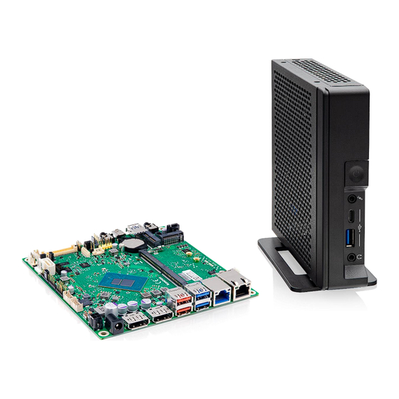
- Page 1 Assembly Instructions SMARTCASE™ S501 - Motherboard K3921-N/H Version V1.0...
-
Page 2: Table Of Contents
Adding Stand / Rubber Feet..........................14 Adding Wall Mount Brackets (optional) ......................15 Active/Passive Cooling – Specific Details ......................16 Technical data are subject to change without prior notice. Kontron accepts no responsibility with regards to technical or editorial mistakes or omissions. SMARTCASE™ S501 Datasheet: https://ftp.kontron.com/main.html?download&weblink=3cb83a90a99c51160d2aa1f1f34cc340&subfolder=Products/Accessories/S... -
Page 3: Delivery Kit & Accessories: Screw Overview
Assembly note: The screws requiring 0.6Nm (e.g. motherboard assembly) are designed for using a hexagonal screwdriver. The additional cross recess is considered as backup only, e.g. for service purpose, if no hexagonal screwdriver is available. // 3 of 17 www.kontron.com... -
Page 4: Preparing The Chassis
Open the chassis with two hands by putting some pressure on your thumbs to push the top cover reverse. Top Cover Rear Cover (K1056-B62x) with integrated EMI gasket Remove top cover and unpack the accessories. Verify position of the additional small square EMI Gasket (position marker is located on chassis bottom) // 4 of 17 www.kontron.com Mainboard... -
Page 5: Inserting Additional Modules (Memory / M.2
Insert M.2 modules angular into the socket (while paying attention to the coding / notch). Any modules have to be touched on the outer edges only. Mandatory torque for the M.2 screw is 0.2Nm, and 0.3Nm for the Key-M nut. // 5 of 17 www.kontron.com... -
Page 6: Heatsink Assembly
Big “cut area” located towards SATA connector Notes: Recommended mounting torque for heatsink screws: 0.6Nm (max. 0.8Nm) Do not remove the insulating foil of the backplate, otherwise the motherboard may be damaged due to possible short circuit. // 6 of 17 www.kontron.com... - Page 7 When using the COM ports respectively connecting the cable, it may be recommended to install the COM connector first before assembling the heatsink. COM2 COM1 Cable Cable Note: COM1 = RS-232 COM2 = RS-232/-422/-485 (BIOS Setup options) // 7 of 17 www.kontron.com...
-
Page 8: Motherboard Assembly
Assemble the four screws (M3x4.5). Mandatory torque = 0.6Nm Note: If you also plan to install chassis intrusion kit you can skip the screw rear right (blue circle) for now // 8 of 17 www.kontron.com... -
Page 9: Installing Wlan Antennas (Optional)
Insert the black antenna cable in the hooks (see red circles), and then plug the black antenna cable to socket #1 of the M.2 WLAN module. Plug the gray antenna cable to socket // 9 of 17 www.kontron.com... -
Page 10: Installing Com Cable/Connector (Optional)
Installing COM Cable/Connector (optional) Note: Due to limited space on rear wall SMARTCASE S501 can only support one rear COM port of K3921! COM cable (S26361-) F5000-K007 Remove carefully COM metal cover first (use of screwdriver recommended). SMARTCASE™ S501 provides the rear aperture for max. one COM port; the cable can be connected to either COM1 or COM2 connector of the motherboard. -
Page 11: Installing Chassis Intrusion Kit For Sc501 (Optional)
Installing Chassis Intrusion Kit for SC501 (optional) Overview F5000-K017 Intrusion Cable S5xx Accessory Set: Intrusion Kit cable K1056-B616 with Intrusion Clamp K1056-C618: Intrusion Carrier K1056-C619: // 11 of 17 www.kontron.com... - Page 12 Install mainboard fixing screw rear right with Intrusion carrier K1056-C619 in between Carefully slide Intrusion switch on installed Intrusion carrier K1056-C619 until it snaps in Connect Intrusion Switch cable on intrusion connector of mainboard // 12 of 17 www.kontron.com...
-
Page 13: Closing The Chassis
Slide the cover on top of the chassis while pushing it forward. Some pressure may be required. Close the chassis rear wall using the screws (M2.5 x 6) included in the SMARTCASE chassis kit. Mandatory torque: 0.4Nm // 13 of 17 www.kontron.com... -
Page 14: Adding Stand / Rubber Feet
The chassis kit includes a desk stand for vertical use, and four rubber feet for horizontal use. Assemble the two M2.5x6.0 screws (0.4Nm) for the desk stand (blue) or the four screws M3x5 (0.4Nm) for the rubber feet (red). “Vertical Use” = Recommended Operating Position due to improved cooling performance // 14 of 17 www.kontron.com... -
Page 15: Adding Wall Mount Brackets (Optional)
11. Adding Wall Mount Brackets (optional) Kontron offers a “Wall Mount Kit” for SMARTCASE S5xx-series: P/N = S26361-F5000-X001 (Kit includes two mounting brackets and four M2.5 mounting screws) 4 x mounting holes for wall mount brackets. Mandatory torque: 0.4Nm // 15 of 17... -
Page 16: Active/Passive Cooling - Specific Details
Note: “Passive Cooling” must be set to [enabled] in order to select/adjust temperature limit Recommended Values. Recommendation does not replaces thermal evaluation in the target application and environment. Battery temperature may be > 60°C if M.2 WLAN module is installed // 16 of 17 www.kontron.com... - Page 17 With the acquisition of Katek SE in early 2024, Kontron significantly strengthens its portfolio with the new GreenTec division, focusing on solar energy and eMobility, and grows to around 8,000 employees in over 20 countries worldwide.
Need help?
Do you have a question about the SMARTCASE S501 and is the answer not in the manual?
Questions and answers