Table of Contents
Advertisement
Quick Links
Advertisement
Table of Contents

Subscribe to Our Youtube Channel
Related Manuals for Kontron SMARC Eval-Carrier-2


Summary of Contents for Kontron SMARC Eval-Carrier-2
- Page 1 USER GUIDE SMARC Eval-Carrier-2 Doc-ID: 1061-6432 Doc. Rev. 1.1...
- Page 2 Kontron with respect to technical processes described in the manual or any product characteristics set out in the manual. Kontron assumes no responsibility or liability for the use of the described product(s), conveys no license or title under any patent, copyright or mask work rights to these products and makes no representations or warranties that these products are free from patent, copyright or mask work right infringement unless otherwise specified.
-
Page 3: Revision History
If you have any difficulties using this user guide, discover an error, or just want to provide some feedback, contact Kontron support. Detail any errors you find. We will correct the errors or problems as soon as possible and post the revised user guide on our website. - Page 4 Kontron sells products worldwide and declares regional General Terms & Conditions of Sale, and Purchase Order Terms & Conditions. Visit http://www.kontron.com/terms-and-conditions. For contact information, refer to the corporate offices contact information on the last page of this user guide or visit our website CONTACT US.
-
Page 5: Symbols
SMARC Eval-Carrier-2 – . Rev. 1.1 Symbols The following symbols may be used in this manual DANGER indicates a hazardous situation which, if not avoided, will result in death or serious injury. WARNING indicates a hazardous situation which, if not avoided, could result in death or serious injury. - Page 6 Therefore, in the interest of your own safety and of the correct operation of your new Kontron product, you are requested to conform with the following guidelines.
- Page 7 General Instructions on Usage In order to maintain Kontron’s product warranty, this product must not be altered or modified in any way. Changes or modifications to the product, that are not explicitly approved by Kontron and described in this User Guide or received from Kontron’s Technical Support as a special handling instruction, will void your warranty.
-
Page 8: Table Of Contents
SMARC Eval-Carrier-2 – . Rev. 1.1 Table of Contents Symbols ..........................................5 Table of Contents ......................................8 List of Tables ........................................9 List of Figures ........................................9 Introduction ......................................11 Description ......................................12 Installation procedure ..................................13 3.1. Packing Check List ..................................... 13 3.2. -
Page 9: List Of Tables
SMARC Eval-Carrier-2 – . Rev. 1.1 8.25. GPIO Header (J38) ....................................55 8.26. Enhanced Serial Peripheral Interface Bus (eSPI) Connector (J47) ..................56 8.27. Power Management Header (J45) ..............................56 8.28. Fan Connector (J62) ....................................57 8.29. Power-In Connector (J53) ................................... 57 8.30. - Page 10 Figure 6: Front Right View ..................................... 21 Figure 7: Rear Side from SMARC Eval-Carrier-2 ........................... 22 Figure 8: Block Diagram for the SMARC Eval-Carrier-2 ........................23 Figure 9: Red Jumper on position INT ............................... 23 Figure 10: Power LEDs, see board position 21 ............................24 Figure 11: GPIO and Backlight LEDs, see board position 19 ........................
-
Page 11: 1/ Introduction
SMARC Eval-Carrier-2 – . Rev. 1.1 1/ Introduction This manual describes the Smart Mobility ARChitecture SMARC Eval-Carrier-2 board. This document describes the electronic, mechanical and thermal design of the SMARC evaluation carrierboard. It is designed for the testing of SMARC-sXAL (2), SMARC_SMX7 and other SMARC 2.0 modules. The board will be equipped with DP++ connector, HDMI connector, LVDS connector, two full-size or half-size mPCIe card slot (PCIe + USB 2.0), two PCIe x1 slot and... -
Page 12: 2/ Description
SMARC Eval-Carrier-2 – . Rev. 1.1 2/ Description The SMARC Eval-Carrier-2 is designed on the latest SMARC 2.0 specification. The board will be equipped with DP++ connector, HDMI connector, LVDS connector, two full-size or half-size mPCIe card slot (PCIe + USB 2.0), ... -
Page 13: 3/ Installation Procedure
SMARC Eval-Carrier-2 – . Rev. 1.1 3/ Installation procedure 3.1. Packing Check List The package includes the following basic items accompany with this manual. One board If this item is damaged or missed, please contact your vendor and save all packing materials for future replacement and maintenance. -
Page 14: 4/ System Specifications
SMARC Eval-Carrier-2 – . Rev. 1.1 4/ System specifications 4.1. Component Main Data The table below summarizes the features of the motherboard. Table 1: Component Main Data SMARC Eval-Carrier-2 Form factor Testing Hardware with 210 mm x 200 mm, max. thickness 3 mm... - Page 15 SMARC Eval-Carrier-2 – . Rev. 1.1 Controller Area two CAN interfaces Network (CAN) LEDs SMD LEDs for storage activity, board status, device and power status (power good) Internal Header and Jumper GPIO GPIO Header 2.54 mm eSPI header eSPI header (2.54 mm pin header, dual row) Power 2.54 mm pin header, dual row...
-
Page 16: Table 2: Environmental Conditions
SMARC Eval-Carrier-2 – . Rev. 1.1 Table 2: Environmental Conditions Operating 0°C to +70°C Some connectors and supercap has operating temperature only 0°C to +70°C, relative humidity (non-condensing) 10 % to 93 % at 40°C Storage -40°C to +85°C relative humidity (non-condensing) 10 % to 95 % at 40°C... -
Page 17: 5/ Jumpers And Connectors
SMARC Eval-Carrier-2 – . Rev. 1.1 5/ Jumpers and Connectors 5.1. Hardware Configuration Setting This chapter gives the definitions and shows the positions of jumpers, headers and connectors. All of the configuration jumpers on the board are in the proper position. The default settings shipped from factory are marked with an asterisk (*). -
Page 18: 5.2. Mainboard Views And I/O Locations
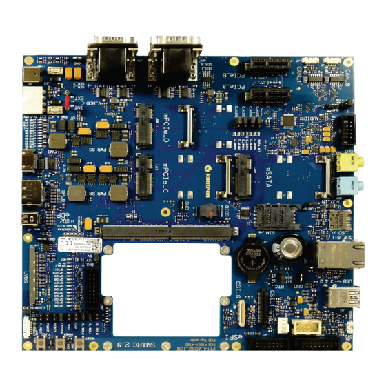
SMARC Eval-Carrier-2 – . Rev. 1.1 Connector Function Remark SD Card (J9) SD card write protect setting Fan (J62) 1x4 header GPIO (J38, U33, U34, GPIO Header 2.54mm 2x8 header U35) 5.2. Mainboard views and I/O locations Figure 2: Top View... -
Page 19: Figure 3: Top View With Leds And Jumper
SMARC Eval-Carrier-2 – . Rev. 1.1 Figure 3: Top View with LEDs and Jumper Jumper Boot Sel 0/1/2, LID, TEST, LED EN, RESET, POWER, F. REC, V DISP 5V 3V3 LEDs GPIO 0-10, 12 V/5 V BKLT, WDT Jumper BKLT 12 V/5 V... -
Page 20: 5.3. Front View
SMARC Eval-Carrier-2 – . Rev. 1.1 5.3. Front View Figure 4: Front View CAN Connector CAN_0 CAN Connector CAN_1 UART SER_0 UART SER_1 UART SER_2 UART SER_3 5.4. Front Left View Figure 5: Front Left View μUSB 2.0 OTG Connector USB 3.0 Port 3... -
Page 21: 5.5. Front Right View
SMARC Eval-Carrier-2 – . Rev. 1.1 5.5. Front Right View Figure 6: Front Right View Power Jack: Main power connector Power-in 4-pin: special power connector, for powering the module only (!) externally, with 3 to 5.25 V. HDMI connector DP connector... -
Page 22: 5.6. Rear Side
SMARC Eval-Carrier-2 – . Rev. 1.1 5.6. Rear Side Figure 7: Rear Side from SMARC Eval-Carrier-2 Rubber feet 6x www.kontron.com // 22... -
Page 23: 6/ Block Diagram
SMARC Eval-Carrier-2 – . Rev. 1.1 6/ Block Diagram Figure 8: Block Diagram for the SMARC Eval-Carrier-2 There are two different ways to power the carrier and module: Default and recommended: Power Connector J53 with 12 V, which also delivers 5 V to the module and 12 V to the board. -
Page 24: 7/ Maintenance And Status Information
SMARC Eval-Carrier-2 – . Rev. 1.1 7/ Maintenance and Status Information 7.1. LEDs Figure 10: Power LEDs, see board position 21 Table 4: Power LEDs LED Color Signal Diode Function Green V_1V8_S5 Voltage V_1V8_S5 is present Green V_1V8_S0 Voltage V_1V8_S0 is... -
Page 25: Table 5: Backlight Voltage Leds
SMARC Eval-Carrier-2 – . Rev. 1.1 Figure 11: GPIO and Backlight LEDs, see board position 19 Table 5: Backlight voltage LEDs LED Color Signal Diode Function Green PG_BKLT_5V LED is shining when voltage is present Green PG_BKLT_12V0 LED is shining when... -
Page 26: Table 7: Watchdog Leds
SMARC Eval-Carrier-2 – . Rev. 1.1 Table 7: Watchdog LEDs LED Color Signal Diode Function Watchdog indication from module Figure 12: GPIO and Backlight LEDs, see board position 25 Table 8: Audio selection LEDs LED Color Signal Diode Function Yellow CODEK_OPTION_SW I2S Codec is active;... -
Page 27: 8/ Pin Definitions
SMARC Eval-Carrier-2 – . Rev. 1.1 8/ Pin Definitions The following sections provide pin definitions and detailed description of all on-board connectors. The connector definitions follow the following notation: Table 12: Connector Definitions Column Name Description Shows the pin-numbers in the connector. The graphical layout of the connector definition tables is made similar to the physical connectors. -
Page 28: Smarc Connector (J1)
SMARC Eval-Carrier-2 – . Rev. 1.1 8.1. SMARC Connector (J1) The SMARC connector has different pins on both sides: Top side: 74 pins are on the left side, 82 pins on the right side Bottom side: 75 pins are on the left side, 83 pins on the right side... - Page 29 SMARC Eval-Carrier-2 – . Rev. 1.1 P-Pin Signal S-Pin Signal GBE0_MDI0- PCIE_D_TX- GBE0_MDI0+ GBE1_LINK_ACT# SPI0_CS1# PCIE_D_RX+ PCIE_D_RX- SDIO_WP SDIO_CMD USB4+ SDIO_CD# USB4- SDIO_CK USB3_VBUS_DET SDIO_PWR_EN AUDIO_MCK I2S0_LRCK SDIO_D0 I2S0_SDOUT SDIO_D1 I2S0_SDIN SDIO_D2 I2S0_CK SDIO_D3 ESPI_ALERT0# SPI0_CS0# ESPI_ALERT1# SPI0_CK RSVD SPI0_DIN...
- Page 30 SMARC Eval-Carrier-2 – . Rev. 1.1 P-Pin Signal S-Pin Signal USB2_EN_OC# USB2_SSTX- RSVD RSVD USB2_SSRX+ USB3_EN_OC# USB2_SSRX- PCIE_A_RST# PCIE_B_RST# USB4_EN_OC# PCIE_C_RST# RSVD PCIE_C_RX+ RSVD PCIE_C_RX- PCIE_C_REFCK+ PCIE_C_TX+ PCIE_C_REFCK- PCIE_C_TX- PCIE_A_REFCK+ PCIE_B_REFCK+ PCIE_A_REFCK- PCIE_B_REFCK- PCIE_A_RX+ PCIE_B_RX+ PCIE_A_RX- PCIE_B_RX- PCIE_A_TX+ PCIE_B_TX+ PCIE_A_TX-...
- Page 31 SMARC Eval-Carrier-2 – . Rev. 1.1 P-Pin Signal S-Pin Signal P106 HDMI_CTRL_DAT S107 LCD1_BKLT_EN / DP1_AUX- P107 DP1_AUX_SEL S108 LVDS1_CK+ / eDP1_AUX+ / DSI1_CLK+ P108 GPIO0 / S109 LVDS1_CK- / CAM0_PWR# eDP1_AUX- / DSI1_CLK- P109 GPIO1 / S110 CAM1_PWR# P110...
- Page 32 SMARC Eval-Carrier-2 – . Rev. 1.1 P-Pin Signal S-Pin Signal P128 POWER_BTN# S129 LVDS0_1- / eDP0_TX1- / DSI0_D1- P129 SER0_TX S130 P130 SER0_RX S131 LVDS0_2+ / eDP0_TX2+ / DSI0_D2+ P131 SER0_RTS# S132 LVDS0_2- / eDP0_TX2- / DSI0_D2- P132 SER0_CTS# S133...
-
Page 33: Lvds Connector (J3)
SMARC Eval-Carrier-2 – . Rev. 1.1 8.2. LVDS Connector (J3) This connector provides data and power connection between Carrier Board and Display. This 30-pin lockable connector contains the LVDS output signals and the power to the LVDS display. Figure 14: 30-pin LVDS connector... - Page 34 SMARC Eval-Carrier-2 – . Rev. 1.1 Signal Description minus signal LVDS_B_CLK+ LVDS even channel clock plus signal LVDS_B_DATA[3]- LVDS even channel 3, minus signal LVDS_B_DATA[3]+ LVDS even channel 3, plus signal Ground FP_STRAP_1 *) Flat panel strapping pin 1 FP_STRAP_2 *)
-
Page 35: Backlight Connector (J40)
SMARC Eval-Carrier-2 – . Rev. 1.1 8.3. Backlight Connector (J40) Figure 15: 7-pin Backlight Connector Signal Type Backlight Brightness 5V or Out (27.4 Ohm series 3.3V (jumper selection J4) resistor) PWM (0% - 100%) Ground V_BKLT - 12V or 5.0V... -
Page 36: Edp Connector (Embedded Display Port) (J8)
SMARC Eval-Carrier-2 – . Rev. 1.1 8.4. eDP connector (embedded Display Port) (J8) The connector provides eDP signals from SMARC board as an option on LVDS pins. Figure 16: 20-pin eDP connector Signal Description Ground Hot plug Detect ML_Lane 0 (p) -
Page 37: Hdmi Connector (J42)
SMARC Eval-Carrier-2 – . Rev. 1.1 8.5. HDMI connector (J42) Figure 17: 19-pin HDMI connector Signal TMDS Data2+ TMDS Data2 Shield TMDS Data2− TMDS Data1+ TMDS Data1 Shield TMDS Data1− TMDS Data0+ TMDS Data0 Shield TMDS Data0− TMDS Clock+ TMDS Clock Shield... -
Page 38: Dp Connector (J12)
SMARC Eval-Carrier-2 – . Rev. 1.1 8.6. DP connector (J12) Figure 18: 20-pin DP connector Signal Signal ML LANE 0+ GND (ML LANE 0) ML LANE 0- ML LANE 1+ GND (ML LANE 1) ML LANE 1- ML LANE 2+... -
Page 39: Mini Pcie Card Socket 2 (J20)
SMARC Eval-Carrier-2 – . Rev. 1.1 Signal Signal PCIe_REFCLK+ UIM-RST UIM-VPP UIM-C8 UIM-C4 W_DISABLE# PLTRST# PCIe_RX- +3.3V_S5 PCIe_RX+ +1.5V_S0 PU 3.3V(S5) (Optional: SMB_CLK) PCIe_TX- PU 3.3V(S5) (Optional: SMB_DAT) PCIe_TX+ USB_D- USB_D+ +3.3V_S5 +3.3V_S5 PU 3.3V(S0) PU 3.3V(S0) N.C. PU 3.3V(S0) N.C. - Page 40 SMARC Eval-Carrier-2 – . Rev. 1.1 Signal Signal PCIe_REFCLK- UIM-CLK PCIe_REFCLK+ UIM-RST UIM-VPP UIM-C8 UIM-C4 W_DISABLE# PLTRST# PCIe_RX- +3.3V_S5 PCIe_RX+ +1.5V_S0 PU 3.3V(S5) (Optional: SMB_CLK) PCIe_TX- PU 3.3V(S5) (Optional: SMB_DAT) PCIe_TX+ USB_D- USB_D+ +3.3V_S5 +3.3V_S5 PU 3.3V(S0) PU 3.3V(S0) N.C.
-
Page 41: Sim Card Socket (J46)
SMARC Eval-Carrier-2 – . Rev. 1.1 8.9. SIM card socket (J46) Figure 21: 8-pin SIM card socket Signal UIM_PWR UIM_RST UIM_CLK UIM_C4 UIM_VPP / NC UIM_DATA UIM_C8 Never use two mPCIe cards in both slots using UIM interface at the same time. SIM Card is directly shared between both slots. -
Page 42: Mini Sata Card Socket (J22)
SMARC Eval-Carrier-2 – . Rev. 1.1 Signal Signal V_12V0_S0 V_12V0_S0 V_12V0_S0 V_12V0_S0 JTAG2_TCK SMCLK JTAG3_TDI SMDAT JTAG4_TDO JTAG5_TMS V_3V3_S0 V_3V3_S0 JTAG1_TRST# V_3V3_S0 V_3V3_AUX PERST# WAKE# RSVD – N.C. REFCLK+ REFCLK- PET0+ PET0- PER0+ PER0- PRSNT2# 8.11. Mini SATA Card Socket (J22) -
Page 43: Audio Connector Line In (J24/J43)
SMARC Eval-Carrier-2 – . Rev. 1.1 Signal Signal SATA_RX+ +3.3V_S5 SATA_RX- +1.5V_S0 PU 3.3V(S5) (Optional: SMB_CLK) SATA_TX- PU 3.3V(S5) (Optional: SMB_DAT) SATA_TX+ USB_D- USB_D+ +3.3V_S5 +3.3V_S5 PU 3.3V(S0) PU 3.3V(S0) N.C. PU 3.3V(S0) N.C. +1.5V_S0 N.C. PU 3.3V(S5) +3.3V_S5 8.12. Audio Connector Line In (J24/J43) -
Page 44: Audio Connector (J10)
SMARC Eval-Carrier-2 – . Rev. 1.1 8.13. Audio Connector (J10) Figure 25: 9-pin Audio Connector Header Signal Signal MIC_L AGND MIC_R PRESENCE# HEADPHONE_R MIC_JD SENSE HEADPHONE _L LINE_JD 8.14. RTC battery holder (J37) Figure 26: RTC battery holder Signal Positive (+) -
Page 45: Μusb 2.0 Otg Connector (J39)
SMARC Eval-Carrier-2 – . Rev. 1.1 8.15. μUSB 2.0 OTG connector (J39) Figure 27: μUSB 2.0 OTG connector Signal +5 V USB output (500 mA max.) USB Data - USB Data + Ground 8.16. J21 – USB Connections Figure 28: USB 2.0 / 3.0 socket USB 2.0... -
Page 46: Figure 29: Usb 2.0 High Speed Cable
SMARC Eval-Carrier-2 – . Rev. 1.1 Signal Description RXn+ RXn- (n= 0,1,2,3) TXn+ TXn- 5 V / SB5 V 5 V supply for external devices. SB5 V is supplied during power-down to allow wakeup on USB device activity. Power is maximum 1 A for each USB 3.0 port (protected with 1 A load switch for each port). -
Page 47: Usb 2.0 Header (J59)
SMARC Eval-Carrier-2 – . Rev. 1.1 8.17. USB 2.0 Header (J59) Figure 31: 9-pin USB Header Signal Signal N.C. +5 V USB output (500 mA max.) USB Data - N.C. USB Data + N.C. Ground N.C. N.C. www.kontron.com // 47... -
Page 48: Double Usb 3.0 Connector (J21)
SMARC Eval-Carrier-2 – . Rev. 1.1 8.18. Double USB 3.0 Connector (J21) This connector provides two USB 3.0 connections (downstream). The 5 V output is electronically fused to 1000 mA each port. Figure 32: Double USB 3.0 Connector Signal Remark VBUS +5V (900mA max.) -
Page 49: Lan Connector (J36 And J41)
SMARC Eval-Carrier-2 – . Rev. 1.1 8.19. LAN Connector (J36 and J41) This connector provides an isolated Ethernet 1000Base-T port, which is connected to an on-board LAN Controller. The galvanic isolated transformers (1500 V , Voltage Regulator Module (VRM)) are integrated in the LAN connectors. -
Page 50: Micro-Μsd Card Connector (J11)
SMARC Eval-Carrier-2 – . Rev. 1.1 8.20. Micro-μSD Card Connector (J11) Figure 34: Micro-μSD Card Connector Signal SD_DAT[2] CD / SD_DAT[3] SD_CLK GND / VSS SD_DAT[0] SD_DAT[1] CD_DETECT CD_GND SH_GND SH_GND SH_GND SH_GND www.kontron.com // 50... -
Page 51: Uart-Ser Connector (J29/J30)
SMARC Eval-Carrier-2 – . Rev. 1.1 8.21. UART-SER Connector (J29/J30) This standard double D-SUB 9-pin connector contains the SER0 and SER1 signals. Figure 35: Double D-SUB 9-pin Connector Table 15: Top SER1/UART1 Signal Direction N.C. RXD (Receive Data) TXD (Transmit Data) N.C. -
Page 52: Can Connector (J6/J7)
SMARC Eval-Carrier-2 – . Rev. 1.1 Table 17: Top SER3/UART3 Signal Direction N.C. RXD (Receive Data) TXD (Transmit Data) N.C. N.C. RTS# Request to Send) CTS# (Clear to Send) N.C. Table 18: Bottom SER2/UART2 Signal Direction N.C. RXD (Receive Data) TXD (Transmit Data) N.C. -
Page 53: Camera Serial Interface (Csi0) Connector (J36)
SMARC Eval-Carrier-2 – . Rev. 1.1 8.23. Camera Serial Interface (CSI0) Connector (J36) Figure 37: 15-pin Camera CSI Connector Signal CSI0_RX0- CSI0_RX0+ CSI0_CLK- CSI0_PCLK CSI0_CLK+ CSI0_RX1+ CSI0_XCLK_1V8 CSI0_RX1+ V_1V8_S0_CSIO V_1V5_S0_CSIO CSIO_HREF CSIO_PWDN_1V8_C CSIO_VSYNC RESET_CSIO_1V8_C CSIO_I2C_CLK_1V8_C V_2V8_DAT_1V8_C CSIO_I2C_DAT_1V8_C AGND_CSI Pin 14: 1.8 V with resettable fuse 0.75 A Pin15: 1.5 V with resettable fuse 0.75 A... -
Page 54: Camera Serial Interface (Csi1) Connector (J61)
SMARC Eval-Carrier-2 – . Rev. 1.1 8.24. Camera Serial Interface (CSI1) Connector (J61) Figure 38: 20-pin Camera CSI Connector Signal CSI1_RX0- CSI1_RX0+ CSI1_RX1- CSI1_RX1+ CSI1_RX2- CSI1_RX2+ CSI1_RX3- CSI1_RX3+ CSI1_CLK- CSI1_CLK+ CSI1_CAM_CLK_1V8 CSI1_I2C_CLK_3V3 CSI1_I2C_DAT_3V3 V_3V3_S0_CSI1 Pin 20 with 3.3 V and 0.75 A resettable fuse www.kontron.com... -
Page 55: Gpio Header (J38)
SMARC Eval-Carrier-2 – . Rev. 1.1 8.25. GPIO Header (J38) Figure 39: 2x8-pin GPIO Header Signal Signal VCC 1.8V VCC 3.3V GPIO_0 GPIO_1 GPIO_2 GPIO_3 GPIO_4 GPIO_5 GPIO_6 GPIO_7 GPIO_8 GPIO_9 GPIO_10 GPIO_11 www.kontron.com // 55... -
Page 56: Enhanced Serial Peripheral Interface Bus (Espi) Connector (J47)
SMARC Eval-Carrier-2 – . Rev. 1.1 8.26. Enhanced Serial Peripheral Interface Bus (eSPI) Connector (J47) Figure 40: 2x7-pin eSPI Connector Signal Signal VCC 1.8V VCC 3.3V ESPI_CS0 ESPI_CS1 ESPI_IO0 ESPI_IO1 ESPI_IO2 ESPI_IO3 ESPI_RESET# ESPI_ALERT0 ESPI_ALERT1 ESPI_CK 8.27. Power Management Header (J45) -
Page 57: Fan Connector (J62)
SMARC Eval-Carrier-2 – . Rev. 1.1 8.28. Fan Connector (J62) Figure 42: 4-pin Fan Connector Signal Description V_S0_FAN 12 V by default. Can optionally be changed to 5 V, via removing FB69 and populating FB68. FAN_TACH_J FAN-Tacho signal FAN_PWMOUT_J PWM output for FAN control 8.29. -
Page 58: Module Power-In Connector (J54)
SMARC Eval-Carrier-2 – . Rev. 1.1 8.30. Module Power-In Connector (J54) Figure 44: Module Power-In Connector Signal Description V_MODULE Module Power from 3.0 V to 5.25 V is independent from Carrier power. Not connected N.C. There are two different ways to power the carrier and module: ... -
Page 59: 8.31. Button Switch
SMARC Eval-Carrier-2 – . Rev. 1.1 8.31. Button Switch Figure 46: Button Switch Table 19: Power Button (SW3, J26) Signal POWER_BTN# POWER_BTN# SHIELD Table 20: Reset Button (SW1, J25) Signal RESET_IN# RESET_IN# SHIELD Table 21: Force Recovery Button (SW4, J27) -
Page 60: 8.32. Boot Selection Jumpers (J28, J32, J33) And Other Jumpers
SMARC Eval-Carrier-2 – . Rev. 1.1 8.32. Boot Selection Jumpers (J28, J32, J33) and other Jumpers There are three Jumpers for Boot Select according to the SMARC 2.0 specification. Figure 47: Jumpers for Boot Select Table 22: Boot Selection Jumpers... -
Page 61: Table 26: Test Jumper (J35)
SMARC Eval-Carrier-2 – . Rev. 1.1 Table 26: TEST Jumper (J35) Jumper Position Function description Open (Default) TEST# not active Close TEST# active Table 27: LEDs Enable Jumper (J44) Jumper Position Function description Open (Default) LEDs not active Close LEDs active... -
Page 62: Table 32: Audio Channel Jumper For I2S Or Hda (J31)
SMARC Eval-Carrier-2 – . Rev. 1.1 Table 32: Audio Channel Jumper for I2S or HDA (J31) Jumper Position Function description Open (Default) HDA Codec Active Close I2S Codec Active Jumper J31 should not be changed when power is present. Table 33: mPCIe-1WLAN Disable Jumper (J49, J50) -
Page 63: List Of Acronyms
SMARC Eval-Carrier-2 – . Rev. 1.1 List of Acronyms Advanced Technology Attachment Serial Communication Port DisplayPort Embedded Controller EEPROM Electrically Erasable Programmable Read Only Memory Electro Static Discharge Flash Non-Volatile Memory FPGA Field Programmable Gate Array Gold Flash Very thin gold plating (e.g. on contacts) -
Page 64: About Kontron
SMARC Eval-Carrier-2 – . Rev. 1.1 About Kontron Kontron, a global leader in embedded computing technology and trusted advisor in Internet of Things (IoT), works closely with its customers, allowing them to focus on their core competencies by offering a complete and integrated portfolio of hardware, software and services designed to help them make the most of their applications.
Need help?
Do you have a question about the SMARC Eval-Carrier-2 and is the answer not in the manual?
Questions and answers