
Related Manuals for Kontron CP305


Summary of Contents for Kontron CP305
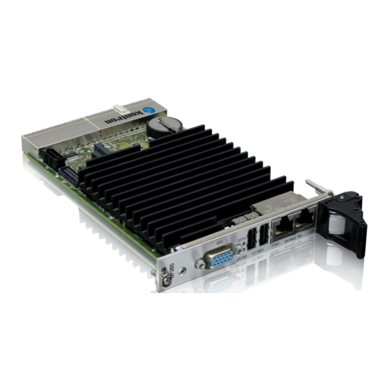
- Page 1 » User Guide « CP305 3U CompactPCI Processor Board based on the Intel® Atom™ Processor N270 with the Mobile Intel® 945GSE Express Chipset Doc. ID: 1035-7168, Rev. 1.0 September 29, 2009 If it’s embedded, it’s Kontron.
-
Page 2: Imprint
Disclaimer Copyright © 2009 Kontron AG. All rights reserved. All data is for information purposes only and not guaranteed for legal purposes. Information has been carefully checked and is believed to be accurate; however, no responsibility is assumed for inaccuracies. Kontron and the Kontron logo and all other trademarks or registered trademarks are the property of their respective own- ers and are recognized. -
Page 3: Table Of Contents
1.5.3 Board Layout .................. 1 - 8 1.6 Technical Specification ................1 - 9 1.7 Kontron Software Support ..............1 - 13 1.8 Standards ....................1 - 14 1.9 Related Publications ................1 - 15 Functional Description ............2 - 3 2.1 CPU, Memory and Chipset .............. - Page 4 Preface CP305 2.1.1 CPU ....................2 - 3 2.1.2 Memory ...................2 - 4 2.1.3 Intel® 945GSE Express Chipset Overview ........2 - 4 2.1.4 Mobile Intel® 945GSE Express Graphics Memory Controller Hub .2 - 4 2.1.5 I/O Controller Hub ICH7-M ..............2 - 5 2.2 Peripherals ....................2 - 5...
- Page 5 3.2 CP305 Initial Installation Procedures ............3 - 4 3.3 Standard Removal Procedures ............... 3 - 5 3.4 Hot Swap Procedures ................3 - 5 3.5 Installation of CP305 Peripheral Devices ..........3 - 5 3.5.1 CompactFlash Installation .............. 3 - 5 3.5.2...
- Page 6 A.2 Technical Specifications ................. A - 4 A.3 CP305-HDD Module Functional Block Diagram ........A - 5 A.4 Front Panel of 8HP CP305 for CP305-HDD Module ......A - 6 A.5 CP305-HDD Module Layout ..............A - 7 A.6 Module Interfaces (Front Panel and Onboard) ........A - 8 A.6.1...
- Page 7 CP305 Preface B. CP-RIO3-04 Rear I/O Module ..........B - 3 B.1 Overview ....................B - 3 B.2 Technical Specifications ................B - 4 B.3 Front Panels ....................B - 5 B.4 Module Layout: 4HP and 8HP Versions ..........B - 6 B.5 Module Interfaces ..................B - 7 B.5.1...
- Page 8 Preface CP305 This page has been intentionally left blank. Page viii ID 1035-7168, Rev. 1.0...
-
Page 9: List Of Tables
2-12 CompactPCI Bus Connector J1 Pinout ........... 2 - 16 2-13 64-bit CompactPCI Bus Connector J2 Pinout (CP305 Front I/O Vers.) .. 2 - 17 2-14 Rear I/O CompactPCI Bus Connector J2 Pinout (CP305 Rear I/O Vers.) 2 - 19 2-15 GPIO Signal Description ................. - Page 10 Input Voltage Characteristics ..............5 - 5 Power Consumption: CP305 with DOS ............5 - 7 Power Consumption: CP305 with Linux / Win.® XP in IDLE Mode ... 5 - 7 Power Consumption: CP305 TDP at 75% ..........5 - 7 Power Consumption: CP305 TDP at 100% ..........
- Page 11 SATA Connector J4 ................2 - 14 CPCI Connectors J1/J2 ................. 2 - 15 Operational Limits for the CP305 Operated in Extended Temp. Range .. 6 - 6 CP305-HDD Module Functional Block Diagram ........A - 5 Front Panel of 8HP CP305 for CP305-HDD Module ....... A - 6 CP305-HDD Module Layout (Top View) ..........
- Page 12 Preface CP305 This page has been intentionally left blank. Page xii ID 1035-7168, Rev. 1.0...
-
Page 13: Proprietary Note
Preface Proprietary Note This document contains information proprietary to Kontron. It may not be copied or transmitted by any means, disclosed to others, or stored in any retrieval system or media without the prior written consent of Kontron or one of its authorized agents. -
Page 14: Explanation Of Symbols
Preface CP305 Explanation of Symbols Caution, Electric Shock! This symbol and title warn of hazards due to electrical shocks (> 60V) when touching products or parts of them. Failure to observe the pre- cautions indicated and/or prescribed by the law may endanger your life/health and/or result in damage to your material. -
Page 15: For Your Safety
However, the life expectancy of your product can be drastically reduced by improper treatment during unpacking and installation. Therefore, in the interest of your own safety and of the correct operation of your new Kontron product, you are requested to conform with the following guidelines. -
Page 16: General Instructions On Usage
CP305 General Instructions on Usage In order to maintain Kontron’s product warranty, this product must not be altered or modified in any way. Changes or modifications to the device, which are not explicitly approved by Kontron and described in this manual or received from Kontron’s Technical Support as a special handling instruction, will void your warranty. -
Page 17: Two Year Warranty
As a result, the products are sold “as is,” and the responsibility to ensure their suitability for any given task remains that of the purchaser. In no event will Kontron be liable for direct, indirect or consequential damages resulting from the use of our hardware or software products, or documentation, even if Kontron were advised of the possibility of such claims prior to the purchase of the product or during any period since the date of its purchase. - Page 18 Preface CP305 This page has been intentionally left blank. Page xviii ID 1035-7168, Rev. 1.0...
-
Page 19: Introduction
CP305 Introduction Chapter Introduction ID 1035-7168, Rev. 1.0 Page 1 - 1... - Page 20 Introduction CP305 This page has been intentionally left blank. Page 1 - 2 ID 1035-7168, Rev. 1.0...
-
Page 21: Board Overview
Introduction Board Overview The CP305 is a highly integrated, 3U, 4 HP or 8 HP, lead-free CompactPCI system controller board. It has been designed to support the Intel® Atom™ Processor N270 with 1.6 GHz frequency and 533 MHz Front Side Bus (FSB) in 437 µFCBGA8 packaging. -
Page 22: Board-Specific Information
• One IDE Ultra ATA/100 interface • Onboard Compact Flash socket for type I and type II CompactFlash cards (True IDE with DMA) on CP305-CF module for 4HP version and CP305-HDD module for 8HP version • Six USB ports • Two Front USB 2.0 •... -
Page 23: Optional Modules
1.3.1 CP305-HDD Module The CP305-HDD module for the 8 HP CP305 version provides legacy PC I/O ports. It includes one digital DVI port, two USB 2.0 ports, one COM port, a PS/2 keyboard and mouse port, one IDE connector, and one CompactFlash socket. A SATA hard disk interface is also available for mounting a 2.5”... -
Page 24: Functional Block Diagram
Introduction CP305 1.5.1 Functional Block Diagram Figure 1-1: CP305 Functional Block Diagram Front Reset, Power Clock Supply Switch Rear DDR2 SDRAM Soldered Up to 1GB (Stacked Up to 2GB) Graphics Intel® Atom™ Memory Processor 533 MHz Controller 533 MHz, 64-bit... -
Page 25: Front Panel
SPEED (green/orange): Ethernet Speed SPEED ON (orange): 1000 Mbit SPEED ON (green): 100 Mbit SPEED OFF: 10 Mbit Note ... For detailed information on the 8HP CP305 version, refer to Appendix A, CP305-HDD module. ID 1035-7168, Rev. 1.0 Page 1 - 7... -
Page 26: Board Layout
Introduction CP305 1.5.3 Board Layout Figure 1-3: 4 HP CP305 Board Layout (Top View) SATA Intel ® Atom ™ Processor N270 Intel ® 945GSE GMCH GP LEDs CompactFlash J10 USB Socket J11A Eth. Contr. Dual DDR2 DDR2 DDR2 DDR2 SDRAM... -
Page 27: Technical Specification
Enhanced DMA controller, interrupt controller, and timer functions • Integrated IDE controller Ultra ATA/100/66/33 and PIO mode • USB 2.0 host interface with up to six USB ports available on the CP305 • SATA Host Controller with two ports, 1.5 Gbit/s transfer rate •... - Page 28 General Purpose signals Hot Swap The CP305 is not hot-swappable but supports the addition and removal of other boards whilst in a powered-up state. Individual clocks for each slot and Enum signal handling are in compliance with the PICMG 2.1 Hot Swap Specification.
- Page 29 SATA: Integrated Serial ATA Host Controllers • Two switchable SATA ports, either: • One onboard SATA port and one SATA port on the CP305-HDD mod- ule (8HP) for 2.5” HDD, or • Two SATA ports available on Rear I/O •...
- Page 30 BIOS parameters are saved in the EEPROM • Board serial number is saved within the EEPROM • PC Health Monitoring Operating Systems There are various operating systems available for the CP305. For detailed infor- mation, please contact Kontron. Page 1 - 12 ID 1035-7168, Rev. 1.0...
-
Page 31: Kontron Software Support
Specifications table in Appendix A, CP305-HDD module. Kontron Software Support Kontron is one of the few CompactPCI and VME vendors providing inhouse support for most of the industry-proven real-time operating systems that are currently available. Due to its close... -
Page 32: Standards
Customers desiring to perform further environmental testing of Kontron prod- ucts must contact Kontron for assistance prior to performing any such testing. This is necessary, as it is possible that environmental testing can be destructive when not performed in accordance with the applicable specifications. -
Page 33: Related Publications
PUBLICATION CompactPCI Systems and CompactPCI Specification PICMG 2.0, Rev. 3.0 Boards CompactPCI Hot Swap Specification PICMG 2.1 Rev. 2.0 Kontron’s CompactPCI System Manual, ID 19954 CompactFlash Cards CF+ and CompactFlash Specification Revision 2.0 Serial ATA Serial ATA 1.0a Specification ID 1035-7168, Rev. 1.0... - Page 34 Introduction CP305 This page has been intentionally left blank. Page 1 - 16 ID 1035-7168, Rev. 1.0...
-
Page 35: Functional Description
CP305 Functional Description Chapter Functional Description ID 1035-7168, Rev. 1.0 Page 2 - 1... - Page 36 Functional Description CP305 This page has been intentionally left blank. Page 2 - 2 ID 1035-7168, Rev. 1.0...
-
Page 37: Cpu, Memory And Chipset
CPU, Memory and Chipset 2.1.1 The CP305 supports the Intel® Atom™ Processor N270 with 1.6 GHz frequency and 533 MHz Front Side Bus (FSB) in 437 µFCBGA8 packaging. The Intel® Atom™ Processor N270 has one core support for two parallel threads (Hyper- Threading) and provides 512 kB L2 cache. -
Page 38: Supported Memory Configurations
2.1.2 Memory The CP305 supports a single-channel DDR2 memory without Error Checking and Correcting (ECC) running at 533 MHz. The maximum memory size is 2 GB. The available memory con- figuration can be either 1 GB or 2 GB. However, due to internal memory allocations, the amount of memory available to applications is less than the total physical memory in the system. - Page 39 CMOS RAM. Features include an alarm function, programmable periodic interrupt and a 100-year calendar. All battery-backed CMOS RAM data remains stored in an additional EEPROM. This prevents data loss in case the CP305 is operated without battery. • Counter/Timer Three 8254-style counter/timers are included on the CP305 as defined for the PC/AT.
-
Page 40: Battery
Functional Description CP305 2.2.3 Battery The CP305 is provided with a 3.0 V “coin cell” lithium battery for the RTC. For further information concerning the battery and its replacement, refer to Chapter 3.5.3, Battery Replacement. Note ... If a CP305-HDD module is used on the CP305, either the CP305 or the CP305-HDD module may be equipped with a battery. -
Page 41: Thermal Management/System Monitoring
BIOS become available. 2.2.8.2 CompactFlash Socket A CompactFlash piggy-back module CP305-CF is installed on the CP305 4HP versions to provide CompactFlash interfacing. CompactFlash is a very small removable mass storage device. It provides true IDE functionality compatible with the 16-bit ATA/ATAPI-4 interface. -
Page 42: Compactflash Socket
Functional Description CP305 Figure 2-1: CompactFlash Socket Page 2 - 8 ID 1035-7168, Rev. 1.0... -
Page 43: Compactflash Connector Pinout
CP305 Functional Description The following table provides the pinout for the CompactFlash connector on the CP305-CF mod- ule. Table 2-5: CompactFlash Connector Pinout FUNCTION SIGNAL SIGNAL FUNCTION Ground Signal Data 3 Data 4 Data 5 Data 6 Data 7 Chip Select 0... -
Page 44: Board Interfaces
Kontron. If the WD/GP LED and the TH/GP LED keep flashing during BIOS initialization, a POST code is indicated. For information on the POST Codes, refer to the CP305 BIOS Guide, Chapter 10, POST Codes. The following table defines the blinking intervals of the WD/GP LED and the TH/GP LED. -
Page 45: Usb Interfaces
USB Interfaces The CP305 supports six USB 2.0 ports (two front I/O, two front I/O on the 8HP version, and two on the Rear I/O module). On the USB 2.0 Rear I/O ports, it is strongly recommended to use a cable below 3 meters in length for USB 2.0 devices. -
Page 46: Graphics Resolution
Ground signal 4,11 * Pin 10 is normally defined as Ground but is used on the CP305 as detection signal of a con- nected monitor if the BIOS setting for the CP305 is “AUTO” (the BIOS default setting is “FRONT”). - Page 47 CP305 Functional Description Note ... The Ethernet transmission can operate effectively using a CAT5 cable with a maximum length of 100 m. The Ethernet connectors are realized as RJ-45 connectors. The interfaces provide automatic detection and switching between 10Base-T, 100Base-TX and 1000Base-T data transmission (Auto-Negotiation).
-
Page 48: Sata Interface
Functional Description CP305 2.3.5 SATA Interface The ICH7-M on the CP305 supports two onboard SATA interfaces that can be switched to rear I/O. The SATA interfaces are running at 1.5 Gbit/s. Table 2-10: SATA Port Mapping SATA PORT ONBOARD CONNECTOR... -
Page 49: Compactpci Bus Interface
CompactPCI backplane connectors support guide lugs to ensure a correct polarized mating (3.3 V or 5 V V(I/O) coding). The CP305 supports universal (3.3 V and 5 V) PCI V(I/O) signaling voltages with one common termination resistor configuration. Therefore, the CP305 can be inserted in both, 3.3V and 5 V CompactPCI systems and provides it-... -
Page 50: Compactpci Connectors J1 And J2 Pinouts
Functional Description CP305 2.3.6.2 CompactPCI Connectors J1 and J2 Pinouts The CP305 is provided with two 2 mm x 2 mm pitch female CompactPCI bus connectors, J1 and J2. Table 2-12: CompactPCI Bus Connector J1 Pinout ROW Z ROW A... - Page 51 CP305 Functional Description Table 2-13: 64-bit CompactPCI Bus Connector J2 Pinout (CP305 Front I/O Vers.) ROW Z ROW A ROW B ROW C ROW D ROW E ROW F CLK6 CLK5 PRST# REQ6# GNT6# DEG# FAL# REQ5# GNT5# AD[35] AD[34]...
-
Page 52: Optional Rear I/O Interface
CPU in the rack as there is practically no cabling on the CPU board. For the system Rear I/O feature a special backplane is necessary. The CP305 with Rear I/O is compatible with all standard CompactPCI passive backplanes with Rear I/O support on the system slot. -
Page 53: Optional Rear I/O Interface On Compactpci Connector J2
GPIO_CFG0 / / out CLK4 GNT3# REQ4# GNT4# CLK2 CLK3 SYSEN# GNT2# REQ3# CLK1 REQ1# GNT1# REQ2# * Pin D7 is an open drain output and has no pull-up resistor on the CP305. ID 1035-7168, Rev. 1.0 Page 2 - 19... -
Page 54: Rear I/O Configuration
GPIO_CFG0 0: COM1; GPIO 1: COM1; COM2 Note ... The default value is 1 if the pin is not connected (pull-up resistor on CP305). If connected, the default value is depending on the Rear I/O module. 2.3.7.2 Rear I/O Configuration Rear I/O interfaces are only available on Rear I/O versions of the board. - Page 55 Serial Interface COM1 and COM2 The COM1 is available either on the front panel of the 8HP CP305 version or on the Rear I/O interface. Switching over from front to Rear I/O or vice versa is effected using the BIOS settings or the board-specific registers (default: front I/O).
- Page 56 Functional Description CP305 This page has been intentionally left blank. Page 2 - 22 ID 1035-7168, Rev. 1.0...
-
Page 57: Installation
CP305 Installation Chapter Installation ID 1035-7168, Rev. 1.0 Page 3 - 1... - Page 58 Installation CP305 This page has been intentionally left blank. Page 3 - 2 ID 1035-7168, Rev. 1.0...
-
Page 59: Safety Requirements
Installation Installation The CP305 has been designed for easy installation. However, the following standard precau- tions, installation procedures, and general information must be observed to ensure proper in- stallation and to preclude damage to the board, other system components, or injury to personnel. -
Page 60: Cp305 Initial Installation Procedures
Installation CP305 CP305 Initial Installation Procedures The following procedures are applicable only for the initial installation of the CP305 in a system. Procedures for standard removal and hot swap operations are found in their respective chap- ters. To perform an initial installation of the CP305 in a system proceed as follows: 1. -
Page 61: Standard Removal Procedures
7. Dispose of the board as required. Hot Swap Procedures The CP305 is not designed for hot swap operation. Do not attempt to hot swap this board. How- ever, the CP305 supports the addition or removal of other boards whilst in a powered-up state. -
Page 62: Usb Device Installation
A suitable battery type is CR2025. Note ... If a CP305-HDD module is used on the CP305, either the CP305 or the CP305-HDD module may be equipped with a battery. Using one battery on the CP305 and one on the CP305-HDD module simulta- neously may result in premature discharge of the batteries. -
Page 63: Hard Disk Installation
3.5.4 Hard Disk Installation The following information pertains to hard disks which may be connected to the CP305 via SATA or IDE cabling. To install a hard disk, it is necessary to perform the following operations in the given order: 1. - Page 64 Installation CP305 This page has been intentionally left blank. Page 3 - 8 ID 1035-7168, Rev. 1.0...
-
Page 65: Configuration
CP305 Configuration Chapter Configuration ID 1035-7168, Rev. 1.0 Page 4 - 1... - Page 66 Configuration CP305 This page has been intentionally left blank. Page 4 - 2 ID 1035-7168, Rev. 1.0...
-
Page 67: Clearing Bios Cmos Setup
Clear the CMOS settings and use the default values The default setting is indicated by using italic bold. I/O Address Map The following table sets out the memory map for the I/O memory. The shaded table cells indicate CP305-specific registers. Table 4-2: I/O Address Map ADDRESS... -
Page 68: Cp305-Specific Registers
CP305 CP305-Specific Registers The following registers are special registers which the CP305 uses to watch the onboard hardware special features and a number of CompactPCI control signals. Normally, only the system BIOS uses these registers, but they are documented here for application use as required. -
Page 69: Watchdog Timer Control Register
CP305 Configuration Watchdog is retriggered normally, operation continues. The interrupt generated at the first tim- eout is available to the application to handle the first timeout if required. As with all of the other modes, the WTE bit is available for application use. -
Page 70: Hardware And Logic Revision Index Register
Configuration CP305 4.3.2 Hardware and Logic Revision Index Register The Hardware and Logic Revision Index Register signals to the software when differences in the hardware and the logic require different handling by the software. It starts with the value 0x00 for the initial board prototypes and will be incremented with each change in hardware as development continues. -
Page 71: Reset Status Register
CP305 Configuration 4.3.3 Reset Status Register The Reset Status Register is used to determine the reset source. The I/O location is 0x285. Table 4-5: Reset Status Register REGISTER NAME RESET STATUS REGISTER SIZE ADDRESS 0x285 8 bits BIT POSITION CONTENT PRST Res. -
Page 72: I/O Status Register
The Rear I/O configuration is shown by the bits RCFG[1:0]. To indicate the active Firmware Hub, the FSTA[1:0] bits are used. The CSLOT bit reflects the kind of slot in which the CP305 is plugged in. The fail signal is an output of the power supply and indicates a power supply failure. -
Page 73: I/O Configuration Register
BBEI BIOS Boot End Indication: 0 BIOS is booting 1 BIOS boot finished SCOM1 COM1 routing selection: 0 Rear I/O 1 CP305-HDD module SETH2 Ethernet 2 routing selection: 0 Front I/O 1 Rear I/O SETH1 Gigabit Ethernet 1 routing selection:... -
Page 74: Board Id Register
Configuration CP305 4.3.6 Board ID Register This register describes the hardware and the board index. The content of this register is unique for each Kontron board. Table 4-8: Board ID Register REGISTER NAME BOARD ID REGISTER SIZE ADDRESS 0x288 8 bits... -
Page 75: Board Interrupt Configuration Register
CP305 Configuration 4.3.7 Board Interrupt Configuration Register The Board Interrupt Configuration register holds a series of bits defining the interrupt routing for the Watchdog. If the Watchdog Timer fails, it can generate an IRQ5 interrupt. The enumeration signal is generated by a hot swap compatible board after insertion and prior to removal. -
Page 76: Bios Configuration Register
Configuration CP305 4.3.8 BIOS Configuration Register The BIOS Configuration Register holds a series of bits defining the onboard configuration. Table 4-10: BIOS Configuration Register REGISTER NAME BIOS CONFIGURATION REGISTER SIZE ADDRESS 0x28A 8 bits BIT POSITION CONTENT Res. Res. Res. -
Page 77: Led Control Register
CP305 Configuration 4.3.9 LED Control Register The LED Control Register enables the user to switch on and off the General Purpose LEDs on the front panel. Table 4-11: LED Control Register REGISTER NAME LED CONTROL REGISTER SIZE ADDRESS 0x28D 8 bits... -
Page 78: Rear I/O Gpio Register
1 Input high Note ... The CP305 provides pull-up resistors on the Rear I/O signal pins GPI[4:0] which leads to the default setting “input high” if the inputs are not connected. The General Purpose Inputs support 3.3V TTL signalling only. -
Page 79: Power Considerations
CP305 Power Considerations Chapter Power Considerations ID 1035-7168, Rev. 1.0 Page 5 - 1... - Page 80 Power Considerations CP305 This page has been intentionally left blank. Page 5 - 2 ID 1035-7168, Rev. 1.0...
-
Page 81: System Power
The table below indicates the absolute maximum input voltage ratings that must not be exceed- ed. Power supplies to be used with the CP305 should be carefully tested to ensure compliance with these ratings. -
Page 82: Backplane
Non-industrial ATX PSUs may require a greater minimum load than a single CP305 is capable of creating. When a PSU of this type is used, it will not power up correctly and the CP305 may hangup. The solution is to use an industrial PSU or to add more load to the system. -
Page 83: Power-Up Sequence
CP305 Power Considerations 5.1.3.2 Power-Up Sequence The +5 VDC output level must always be equal to or higher than the +3.3 VDC output during power-up and normal operation. Both voltages must reach their minimum in-regulation level not later than 20 ms after the output power ramp start. -
Page 84: Regulation
CP305 accessories. The values were measured using an 8-slot passive Com- pactPCI backplane with two power supplies: one for the CP305 (5V and 3.3V power supply), and the other for the hard disk. The operating systems used were DOS, Linux and Windows ®... -
Page 85: Power Consumption: Cp305 With Dos
INTEL® ATOM™ PROCESSOR N270 5.8 W 3.3 V 2.3 W Total 8.1 W Table 5-5: Power Consumption: CP305 with Linux / Win.® XP in IDLE Mode POWER INTEL® ATOM™ PROCESSOR N270 5.1 W 3.3 V 2.6 W Total 7.7 W... -
Page 86: Power Consumption Of Cp305 Accessories
800 mW Start-Up Currents of the CP305 The following table indicates the start-up currents of the CP305 during the first 2-3 seconds af- ter the power supply has been switched on. The power consumption of the CP305 during op- eration is indicated in tables 5-4 to 5-8. -
Page 87: Thermal Considerations
CP305 Thermal Considerations Chapter Thermal Considerations ID 1035-7168, Rev. 1.0 Page 6 - 1... - Page 88 Thermal Considerations CP305 This page has been intentionally left blank. Page 6 - 2 ID 1035-7168, Rev. 1.0...
-
Page 89: Board Internal Thermal Regulation
CP305 applications. Board Internal Thermal Regulation The thermal management architecture implemented on the CP305 can be described as being two separate but related functions. The goal of these functions is to protect the processor and the chipset. Enabling the thermal control circuit allows the processor and the chipset to main- tain a safe operating temperature without the need for special software drivers or interrupt han- dling routines. -
Page 90: Cpu Emergency Thermal Supervision (Thermtrip)
The Thermal Management feature allows system designers to design low- er cost thermal solutions without compromising system integrity or reliability. If the system environment is not optimized for the CP305, the internal Thermal Monitor should be enabled. The internal Thermal Monitor protects the processor, the chipset and the system against excessive temperatures. -
Page 91: Convection Cooling
6.2.1 Convection Cooling The CP305 can also be employed in applications cooled by natural convection only. In order to ensure maximum cooling efficiency, the CP305 must be installed vertically in the chassis or ap- plication. To allow the air to freely flow around the heat sink, it is necessary to avoid air trapping above the CP305. -
Page 92: Operational Limits For The Cp305 Operated In Extended Temp. Range
The airflow is specified in m/s = meter-per-second or in fps = feet-per-second, respectively. Conversion: 1 fps = 0.3048 m/s; 1 m/s = 3.28 fps The following figures illustrate the operational limits of the CP305 taking into consideration power consumption vs. ambient air temperature vs. airflow rate. The measurements were made based on a 4HP slot. -
Page 93: Peripherals
CP305 must also be considered. Devices such as hard disks, extension modules, etc. which are directly attached to the CP305 must also be capable of being operated at the tem- peratures foreseen for the application. It may very well be necessary to revise system require- ments to comply with operational environment conditions. - Page 94 Thermal Considerations CP305 This page has been intentionally left blank. Page 6 - 8 ID 1035-7168, Rev. 1.0...
- Page 95 CP305 CP305-HDD Appendix CP305-HDD ID 1035-7168, Rev. 1.0 Page A - 1...
- Page 96 CP305-HDD CP305 This page has been intentionally left blank. Page A - 2 ID 1035-7168, Rev. 1.0...
-
Page 97: Cp305-Hdd Module
CompactFlash socket, a DVI-D flat panel interface, a PLCC FWH Flash socket and a battery socket. The CP305-HDD module extends the CP305 version from 4 HP to 8 HP. This additional capability opens up the broadest range of expansion possibilities. -
Page 98: Technical Specifications
93% RH at 40°C, non-condensing (acc. to IEC 60068-2-78) Dimensions Dimensions: 100 mm x 150 mm Board Weight CP305 8HP with heat sink: 540 grams (with mounted 2.5” HDD) Battery 3.0V lithium battery for RTC with battery socket. Recommended type: CR2025 Temperature ranges: Operational: -20°C to +70°C... -
Page 99: Cp305-Hdd Module Functional Block Diagram
CP305 CP305-HDD CP305-HDD Module Functional Block Diagram Figure A-1: CP305-HDD Module Functional Block Diagram SDVO Panel Link Transmitter High Speed I/O Ext. SATA Connector SATA Compact 40Pins Connector Flash Socket IDE/CF 2x USB USB 2.0 Extension Connector 32Pins Connector Battery... -
Page 100: Front Panel Of 8Hp Cp305 For Cp305-Hdd Module
CP305-HDD CP305 Front Panel of 8HP CP305 for CP305-HDD Module Figure A-2: Front Panel of 8HP CP305 for CP305-HDD Module LEGEND: CP305: 8HP version CP305 General Purpose LEDs: WD/GP (green): Watchdog or General Purpose; when lit during power-on, it indicates a PCI reset is active. -
Page 101: Cp305-Hdd Module Layout
CP305 CP305-HDD CP305-HDD Module Layout Figure A-3: CP305-HDD Module Layout (Top View) HDD LED & Reset Button (PATA) 2.5” SATA SATA HARD DISK DRIVE PS/2 COM1 Figure A-4: CP305-HDD Module Layout (Bottom View) CompactFlash Socket PLCC Socket ID 1035-7168, Rev. 1.0... -
Page 102: Module Interfaces (Front Panel And Onboard)
CP305 Module Interfaces (Front Panel and Onboard) A.6.1 Keyboard/Mouse Interface The keyboard controller is located on the CP305 and is 8042 software compatible. Figure A-5: Keyboard/Mouse Connector The PC/AT standard keyboard/mouse connector is a PS/2-type 6-pin shielded Mini-DIN connector. A special adapter to connect a mouse device and/or a keyboard to the PS/2 connector ia available from Kontron. -
Page 103: Universal Serial Port
CP305 CP305-HDD The CP305 has the AT keyboard connector implemented on a 6-pin Mini-Din connector. Figure A-7: Keyboard Connector J7 Pinout SIGNAL DESCRIPTION KDATA Keyboard data MDATA Mouse data Ground signal VCC signal KCLK Keyboard clock MCLK Mouse clock Note ... -
Page 104: Usb Interfaces
The CP305-HDD provides two standard USB 2.0 ports on J4 and J6. The CP305-HDD supports two USB 2.0 ports. The USB 2.0 ports are high-speed, full-speed, and low-speed capable. Hi-speed USB 2.0 allows data transfers of up to 480 Mb/s - 40 times faster than a full-speed USB (USB 1.1). -
Page 105: Dvi-D Interface
CP305 CP305-HDD A.6.4 DVI-D Interface The CP305-HDD provides one standard DVI-D interface, J2, which is a digital signal only interface with device detection. Figure A-10: DVI-D Connector J2 The following table indicates the pinout of the DVI-D Connector J2. Table A-4: DVI-D Connector J2 Pinout... -
Page 106: Ide Interface (Pata)
Please contact Kontron for further information. A wide range of IDE devices may be connected to the CP305-HDD module at J3 using a ribbon cable. The following table describes the pinout of connector J3. -
Page 107: Compactflash Socket
The CompactFlash socket is connected to the IDE port of the ICH7-M and is set to master con- figuration. The CP305 supports DMA and both CF type I and CF type II. Note ... An installed CompactFlash card is always configured as IDE master. For this reason, only one additional external IDE slave device may be connected to the CP305-HDD if a CompactFlash card is installed. -
Page 108: Compactflash Connector J13 Pinout
Ground Signal * Signal terminated with 10 kΩ pull-down resistor Note ... The CompactFlash socket on the CP305-HDD supports all available Compact- Flash cards type I and type II with 5 V power supply. Page A - 14 ID 1035-7168, Rev. 1.0... -
Page 109: Sata Interface
CP305-HDD A.6.7 SATA Interface The SATA connector, J5, on the CP305-HDD module is provided for connecting a 2.5” SATA HDD to the CP305-HDD module. The SATA connector is divided into two segments, a signal segment and a power segment. Figure A-11: SATA Connector J5... -
Page 110: Plcc Socket
A 32-pin PLCC socket, J14, is available for installing a FWH flash on the CP305-HDD module. This flash can be used for booting the CP305 in case of a crash of the onboard firmware hub flash. The jumper J1 must be set prior to applying power to the system in order to boot the CP305 from the FWH flash on the CP305-HDD module. - Page 111 CP305 CP-RIO3-04 Rear I/O Appendix CP-RIO3-04 Rear I/O ID 1035-7168, Rev. 1.0 Page B - 1...
- Page 112 CP-RIO3-04 Rear I/O CP305 This page has been intentionally left blank. Page B - 2 ID 1035-7168, Rev. 1.0...
-
Page 113: Cp-Rio3-04 Rear I/O Module
CompactPCI systems. Some standard PC interfaces are imple- mented and assigned to the front panel and to the Rear I/O connector J2 on the CP305. When the CP-RIO3-04 Rear I/O module is used, the signals of some of the main board/front panel connectors are routed to the module interface. -
Page 114: Technical Specifications
CP-RIO3-04 Rear I/O CP305 Technical Specifications Table B-1: CP-RIO3-04 Rear I/O Module Main Specifications CP-RIO3-04 Rear I/O SPECIFICATIONS Two USB 2.0 interfaces; two 4-pin connectors One VGA interface; 15-pin D-Sub connector Ethernet Two Gigabit Ethernet interfaces implemented as dual RJ-45 connector without LEDs Two serial ports (COM1 and COM2), RS-232;... -
Page 115: Front Panels
CP305 CP-RIO3-04 Rear I/O Front Panels Figure B-1: CP-RIO3-04 Front Panels, 4HP and 8HP Versions CP-RIO3-04 CP-RIO3-04 4 HP 8 HP ID 1035-7168, Rev. 1.0 Page B - 5... -
Page 116: Module Layout: 4Hp And 8Hp Versions
CP-RIO3-04 Rear I/O CP305 Module Layout: 4HP and 8HP Versions Figure B-2: CP-RIO3-04 Module Layout, 4HP Version CPCI Peripheral Control Dual COM1 Gigabit Ethernet COM2 SATA-B SATA-A Figure B-3: CP-RIO3-04 Module Layout, 8HP Version ribbon cable COM1 CPCI Peripheral Control... -
Page 117: Module Interfaces
CP305 CP-RIO3-04 Rear I/O Module Interfaces B.5.1 USB Interfaces There are two identical USB interfaces on the CP-RIO3-04 Rear I/O module, each with a max- imum transfer rate of 480 Mb/s provided for connecting USB devices. One USB peripheral may be connected to each port. -
Page 118: Vga Interface
CP-RIO3-04 Rear I/O CP305 B.5.2 VGA Interface The 15-pin female connector J7 is used to connect a VGA monitor to the CP-RIO3-04 Rear I/O module. Figure B-5: D-Sub VGA Con. J7 Table B-3: D-Sub VGA Connector J7 Pinout SIGNAL FUNCTION... -
Page 119: Gigabit Ethernet Interface
CP305 CP-RIO3-04 Rear I/O B.5.3 Gigabit Ethernet Interface Figure B-6: Dual Gigabit Ethernet Connector J10A/B The Ethernet connectors are realized as RJ-45 con- nectors. The interface provides automatic detection and switching between 10Base-T, 100Base-TX and 1000Base-T data transmission (Auto-Negotiation). J10A Auto-wire switching for crossed cables is also support- ed (Auto-MDI/X). -
Page 120: Com Interface
CP-RIO3-04 Rear I/O CP305 B.5.4 COM Interface The CP-RIO3-04 Rear I/O module provides two identical COM ports for connecting RS-232 de- vices to the CP-RIO3-04 Rear I/O module. On the 8HP version, the onboard 10-pin COM connectors J2 and J3 are routed to the 9-pin D- Sub COM connectors J2a and J3a located on the front panel. -
Page 121: Peripheral Control Interface
CP305 CP-RIO3-04 Rear I/O B.5.5 Peripheral Control Interface A fan for system cooling and a power supply with power management can be connected via the peripheral control connector J13. The following figure and table provide pinout information for the power connector J13. -
Page 122: Serial Ata Interfaces Sata-A And Sata-B
Note ... When using a Serial ATA cable, it is recommended to use a special right-angled Serial ATA cable due to possible space limitations within the system. For further information, please contact Kontron. Page B - 12 ID 1035-7168, Rev. 1.0... -
Page 123: Rear I/O Interface On Compact Pci Connector Rj2
CP305 CP-RIO3-04 Rear I/O B.5.7 Rear I/O interface on Compact PCI Connector rJ2 The CP-RIO3-04 Rear I/O module conducts a wide range of I/O signals through the Rear I/O connector rJ2. Warning! To support the Rear I/O feature a special backplane is necessary. Do not plug a Rear I/O configured board in a non-system slot Rear I/O backplane. -
Page 124: Rear I/O Compactpci Connector Rj2
CP-RIO3-04 Rear I/O CP305 Table B-9: Rear I/O CompactPCI Connector rJ2 Pinout ROW Z ROW A ROW B ROW C ROW D ROW E ROW F USB1P / bi USB3P / bi USB1_5V / in USB1N / bi USB3N / bi... - Page 125 CP305 CP-RIO3-04 Rear I/O Legend for Table B-4: SATAx Serial ATA port Gigabit Ethernet port USBx USB interface and power VGAx VGA signals COM1x COM1 port GPIOx COM2 port or GPIO PWRx Power Management signals 5V/3.3V Power GPIO_CFG0 GPIO configuration (GPIO or COM2) ID 1035-7168, Rev.
- Page 126 CP-RIO3-04 Rear I/O CP305 This page has been intentionally left blank. Page B - 16 ID 1035-7168, Rev. 1.0...
Need help?
Do you have a question about the CP305 and is the answer not in the manual?
Questions and answers