
Related Manuals for Kontron nanoETXexpress


Summary of Contents for Kontron nanoETXexpress
- Page 1 Kontron User’s Guide nanoETXexpress Evaluation Board Document Revision 0.10_Preliminary...
- Page 2 This page intentionally left blank...
-
Page 3: Table Of Contents
6.10 VGA & LVDS (J6, J33) ..................25 6.11 TV-Out (J28, J31) .................... 26 6.12 Kontron Feature Connector (J37) ............... 27 6.13 PCIexpress (J25, J26, J27, U31 and Status LEDs) ........... 29 6.14 PCI (J38, J39, U38) ..................30 6.15 ... - Page 4 6.20 CPLD (J47, U44) ....................37 7 Battery Information (BT1) ..................38 8 Security advice ......................40 9 Limitations ......................41 10 Appendix A - Product Compatibility ................42 11 Document History ...................... 43 Kontron User's Guide nanoETXexpress Evaluation Board...
-
Page 5: User Information
“as-is” and is subject to change without notice. For the circuits, descriptions and tables indicated, Kontron assumes no responsibility as far as patents or other rights of third parties are concerned. -
Page 6: Technical Support
Kontron Embedded Modules GmbH will not be responsible for any defects or damages to other products not supplied by Kontron Embedded Modules GmbH that are caused by a faulty Kontron Embedded Modules GmbH product. -
Page 7: Specifications
2 1BSpecifications Specifications Mechanical Specifications The nanoETXexpress UGM Evaluation Board is 304.8mm x 210.8mm in size and compares to ATX form factor with 12" x 8.3". The maximum height on top is the audio connector J8 with 34,7mm. Kontron User's Guide... - Page 8 2 1BSpecifications Kontron User's Guide nanoETXexpress Evaluation Board...
-
Page 9: Environmental Specifications
The maximum operating temperature is the maximum measurable temperature on any spot on a baseboards’ surface. You must maintain the temperature according to the above specification. 2.2.2 Humidity Operating: 10% to 90% (non condensing) Non operating: 5% to 95% (non condensing) Kontron User's Guide nanoETXexpress Evaluation Board... -
Page 10: Short Description
3 2BShort description Short description The Kontron nanoETXexpress Evaluation Board is a Type 1 COM Express baseboard compatible to the new nanoETXexpress standard. COM Express Type 2 modules in basic and compact size can also be used without the features of Connector C/D. -
Page 11: Block Diagram
4 3BBlock Diagram Block Diagram Kontron User's Guide nanoETXexpress Evaluation Board... - Page 12 4 3BBlock Diagram Kontron User's Guide nanoETXexpress Evaluation Board...
-
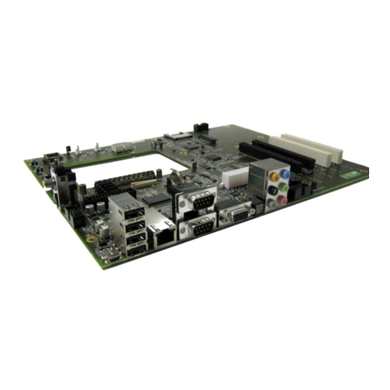
Page 13: Connector Locations
5 4BConnector locations Connector locations Kontron User's Guide nanoETXexpress Evaluation Board... - Page 14 5 4BConnector locations Kontron User's Guide nanoETXexpress Evaluation Board...
- Page 15 LPC-IO Winbond W83627HF SUS_S3 SPI Flash (optional) SUS_S4 HDD Activity LED SUS_S5 Watchdog Trigger LED THRMTRIP Port80 MSB PCIe x1 Slot1 Port80 LSB PCIe x1 Slot0 XpressCard PCIe-PCI Bridge PCIe Switch Upstream PCIe Switch Fatal Error Kontron User's Guide nanoETXexpress Evaluation Board...
-
Page 16: Connector And Feature Description
The Kontron nanoETXexpress Evaluation Baseboard offers the possibility to connect a full featured Type1 module following the new standard form factor nanoETXexpress or to connect a Type2 module like ETXexpress in basic or micro size without the features of the second connector C/D. -
Page 17: Atx Power Connector (J15, J22)
The 12V power connector mainly supplies power to the module. If the ATX_12V power connector is not connected, the system will not start. 24 pin ATX Power 4 pin ATX_12V +3.3VDC +3.3VDC +3.3VDC -12VDC +12VDC +5VDC PS_ON +12VDC +5VDC PWR_OK -5VDC +5VSB +5VDC +12VDC +5VDC +12VDC +5VDC +3.3VDC Kontron User's Guide nanoETXexpress Evaluation Board... -
Page 18: Power, Reset & Ps_On Override (Sw1, Sw2, J14, J40, J42)
J40 (Power Button) and J42 (Reset Button) are pin header to connect a switch on the chassis front panel. With the manual PS_ON override Jumper J26 you are able to switch the Power Supply on or off manually. Note: Blue Jumpers and bold marked text shows Kontron default settings Kontron User's Guide nanoETXexpress Evaluation Board... -
Page 19: Status Leds & Post Code Display
LED D38 shows hard disk activity for connected SATA devices. D40 (Port80 MSB) and D42 (Port80 LSB) shows the actual POST Codes if the module BIOS is configured to send POST Code cycles to the LPC Bus. Kontron User's Guide nanoETXexpress Evaluation Board... -
Page 20: Sata (J29, J30, J32, J34)
The COM Express specification provides 4 SATA channels maximum. Please check how many SATA ports are supported by the used COMexpress module. SATA Connector Pin out Connector Configuration Signal Connector SATA Port SATA2 SATA3 SATA0 SATA1 Refer to the COMexpress module manual how to enable and configure SATA. Kontron User's Guide nanoETXexpress Evaluation Board... -
Page 21: Usb (J7, J23)
6 5BConnector and feature description USB (J7, J23) COM Express defines a maximum of 8 USB Ports. On nanoETXexpress Evaluation Baseboard 4 USB Ports (USB0-USB3) are provided via rear panel connector J7 and two (USB4 & USB5) ports via onboard pin header (J23). -
Page 22: Usb Client (J3)
6 5BConnector and feature description USB Client (J3) With nanoETXexpress a new function called USB Client is coming up. If supported by the used chipset on the module, USB Port7 is used as an USB Client connection via MiniUSB Connector TypeA (J3). The client function is a software implemented USB device in the chipset which allows connecting the platform to other USB Host interfaces for purposes of file transfer, network connectivity or any other USB functions. -
Page 23: Ethernet (J10)
J16-J20 (default). For modules with only 10/100MBit connection (e.g. microETXexpress) open all Jumpers. J10 Ethernet LED function State Function Green Link1000 1 (left) Yellow Link100 Link10 Link 2 (right) Blinking Activity Kontron User's Guide nanoETXexpress Evaluation Board... -
Page 24: High Definition Audio (J2, J4, J5, J8, J11, J12)
Note1: In addition to the default speaker settings, the analog audio Jacks can be reconfigured to perform different functions via the Realtek HDAudio Driver Software which is available on Kontron website. Only microphones still must be connected to the default pink jack. -
Page 25: Vga & Lvds (J6, J33)
LVDS_A_CK+ ID1 (DDC_DAT) HSYNC LVDS_A3- VSYNC LVDS_A3+ ID3 (DDC_CLK) BLON# JILI_DAT LVDS_B0- LVDS_B0+ +12V JILI_CLK +12V LVDS_B1- +12V For a detailed description of LVDS JILI interface refer to the JILI documentation on Kontron’s webpage. Kontron User's Guide nanoETXexpress Evaluation Board... -
Page 26: Tv-Out (J28, J31)
6 5BConnector and feature description 6.11 TV-Out (J28, J31) The nanoETXexpress Evaluation Baseboard provides three possible TV-Out connections. Composite Video (Yellow Cinch) and S-Video out are available on connector J31. Component TV-Out is available via pin header J28. TV-Out connector Pin out... -
Page 27: Kontron Feature Connector (J37)
6 5BConnector and feature description 6.12 Kontron Feature Connector (J37) The Feature Connector J37 is a Kontron standard connection for easy communication with external devices for example SM Bus communication with Kontron M.A.R.S. Smart Battery System. See the detailed description of available functions below:... - Page 28 Power Button Input. This input is used to support the ACPI Power Button function. Ground #ATA_ACT 3.3V-O Low active output signal, which indicates activity on IDE interfaces. #CB_RESET 3.3V-O Low active Reset output from module to carrier board Kontron User's Guide nanoETXexpress Evaluation Board...
-
Page 29: Pciexpress (J25, J26, J27, U31 And Status Leds)
PCIexpress lane0 from the COMexpress module is used to connect a 5-lane PCIexpress Gen1 switch PEX8505AA. The Type 1 connection of the nanoETXexpress Evaluation Board offers a maximum of 5 PCIe lanes from the module (PCIe0 ... PCIE4). The switch provides 4 additional PCIexpress lanes (PCIe5 …... -
Page 30: Pci (J38, J39, U38)
PCI (J38, J39, U38) According to the COMexpress specification PCI usually is provided by connector C/D. On the nanoETXexpress Evaluation Board with Type1 connection PCI must be generated with a PCIexpress to PCI Bridge. The PCIe-toPCI Bridge PEX8112AA provides a maximum of 4 PCI Slots. PCI Slot0 (J38) and PCI Slot1 (J39) can be used on the nanoETXexpress Evaluation Board. -
Page 31: Express Card (J41, J49)
3.3VS_0 USB_D+ CLKREQ# CPUSB# CPPE# REFCLK- REFCLK+ SMB_CLK SMB_DATA PERN0 1.5V_2 PERP0 1.5V_1 GND_1 WAKE# PETN0 3.3VAUX PETP0 PERST# GND_0 Jumper J49 switches ExpressCard Reset between 'ModuleHotplug' (Closed Jumper, default) and CB_Reset# (Open Jumper) Kontron User's Guide nanoETXexpress Evaluation Board... -
Page 32: Sdio & Gpio (J43, J48)
6.16 SDIO & GPIO (J43, J48) COMexpress defines a maximum of 4GPIs and 4 GPOs. With the new nanoETXexpress standard the 8 General Purpose Input/Output signals alternatively can be configured as SDIO interface. Refer to the module's manual if SD Card feature is supported and how to be configured. -
Page 33: Lpc-I/O Controller (J21, U53))
Baseboard's Super I/O Address with jumper J25. SIO address switch J21 Jumper Address closed open Note: To use the LPC-I/O functions like COM, LPT and hardware monitoring features a Kontron module with legacy BIOS is necessary. Kontron User's Guide nanoETXexpress Evaluation Board... -
Page 34: Lpc-I/O Fan Control (J44, J45)
To support FAN control and monitoring it is required to set the LPC Decode Range 1 Base to 290h and the Range 1 Size to 8B in the module BIOS. Refer to the module's manual for more details. Kontron User's Guide nanoETXexpress Evaluation Board... -
Page 35: Lpci-I/O Parallel And Serial Ports (J9, J13, J24)
J13-COM2 COM1/COM2 J13-COM2 #STB #AFD #ERROR #INIT #SLCTIN VCC_5V #ACK BUSY SLCT n.c. Note: To use the LPC-I/O functions like COM, LPT and hardware monitoring features a Kontron module with legacy BIOS is necessary. Kontron User's Guide nanoETXexpress Evaluation Board... -
Page 36: Backup Bios (U48, J46)
6.19 Backup BIOS (U48, J46) The nanoETXexpress Evaluation Baseboard provides a backup LPC Firmware Hub U48. The backup BIOS must be activated with jumper J46. The yellow marked components are for an optional SPI flash (U57). In case of using an SPI flash jumper J52 must be closed to activate it. -
Page 37: Cpld (J47, U44)
6 5BConnector and feature description 6.20 CPLD (J47, U44) Current Kontron products are equipped with a Altera CPLD (Complex Programmable Logic Device) for power up sequencing and other functionalities. The nanoETXexpress Evaluation Baseboard's CPLD (U44) can be accessed by connector J47... -
Page 38: Battery Information (Bt1)
7 6BBattery Information (BT1) Battery Information (BT1) The nanoETXexpress Evaluation Baseboard includes a standard CR2032 3V RTC battery. English: CAUTION: Danger of explosion if battery is incorrectly replaced. Replace only with the same or equivalent type recommended by the manufacturer. Dispose of used batteries according to the manufacturer’s instructions. - Page 39 English, German, French, Danish, Finish and Spanish language. If the battery of this product however is accessible by the end user, it is in the responsibility of the Kontron customer to give the corresponding safety instructions in the required language(s). Kontron User's Guide...
-
Page 40: Security Advice
To protect the external power lines to peripheral devices the customer has to take care about: - The wires to the external device have the right diameter to withstand the max. available current - The housing of the external device fulfils the fire protection requirements of IEC/EN 60950. Kontron User's Guide nanoETXexpress Evaluation Board... -
Page 41: Limitations
The octal buffer is not able to switch between SDIO and GPIO. SD Card interface is only working with desoldered buffer and assembled R380. A manual switching via jumper will be implemented in newer designs. ® The optional SPI Flash U57/J52 is not supported. Kontron User's Guide nanoETXexpress Evaluation Board... -
Page 42: Appendix A - Product Compatibility
10 9BAppendix A - Product Compatibility Appendix A - Product Compatibility A short overview which baseboard functions can be used on Kontron COMexpress modules: USB Client SDIO PCIe 0 PCIe 1-4 GB LAN SATA 0-3 TV-out nanoETXexpress-SP SATA 0 microETXexpress-SP... -
Page 43: Document History
11 10BDocument History Document History Rev. Date Edited by Changes 0.10_prelim 08.10.08 Initial Release Kontron User's Guide nanoETXexpress Evaluation Board...
Need help?
Do you have a question about the nanoETXexpress and is the answer not in the manual?
Questions and answers