
Subscribe to Our Youtube Channel
Related Manuals for Kontron SMARTCASE S511


Summary of Contents for Kontron SMARTCASE S511
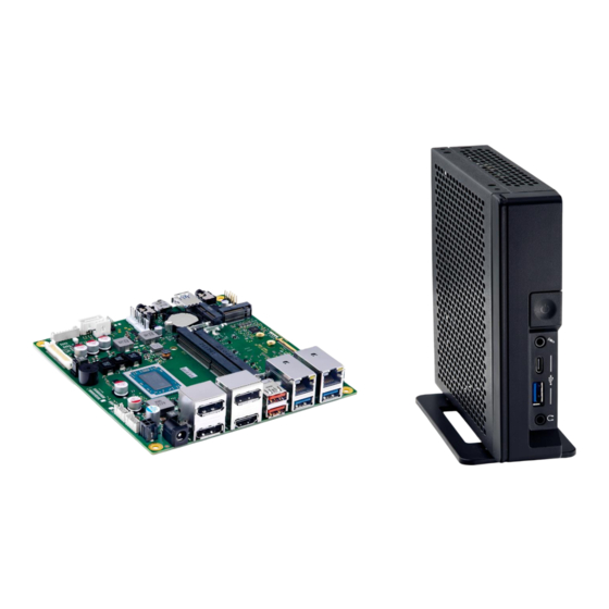
- Page 1 Assembly Instructions SMARTCASE™ S511 - Motherboard D3714-V/R & D3724-R Version V1.1...
-
Page 2: Table Of Contents
Adding Stand / Rubber Feet ............................ 12 Adding Wall Mount Brackets (optional) ......................... 13 Active/Passive Cooling – Specific Details ....................... 14 Technical data are subject to change without prior notice. Kontron accepts no responsibility with regards to technical or editorial mistakes or omissions. SMARTCASE™ S511 Datasheet: https://ftp.kontron.com/main.html?download&weblink=3cb83a90a99c51160d2aa1f1f34cc340&subfolder=Products/Accessories/S... -
Page 3: Delivery Kit & Accessories: Screw Overview
Assembly note: The screws requiring 0.6Nm (e.g. motherboard assembly) are designed for using a hexagonal screwdriver. The additional cross recess is considered as backup only, e.g. for service purpose, if no hexagonal screwdriver is available. // 3 of 15 www.kontron.com... -
Page 4: Preparing The Chassis
K1056-B621: Supporting up to 3 x graphics and 1 x rear COM K1056-B622: Supporting 4 x graphics (no rear COM support) See chapter 8. for details Verify position of the additional small square EMI Gasket (position marker is located on chassis bottom) // 4 of 15 www.kontron.com... -
Page 5: Inserting Additional Modules (Memory / M.2
Insert M.2 modules angular into the socket (while paying attention to the coding / notch). Any modules have to be touched on the outer edges only. Mandatory torque for the M.2 screw is 0.2Nm, and 0.3Nm for the Key-M nut. // 5 of 15 www.kontron.com... -
Page 6: Heatsink Assembly
Recommended mounting torque for heatsink screws: 0.6Nm (max. 0.8Nm) Do not remove the insulating foil of the backplate, otherwise the motherboard may be damaged due to possible short circuit. Big “cut area” located towards LVDS connector // 6 of 15 www.kontron.com... - Page 7 When using the COM ports respectively connecting the cable, it may be recommended to install the COM connector first before assembling the heatsink. COM1 COM2 Cable Cable Note: COM1 = RS-232 COM2 = RS-232/-422/-485 (BIOS Setup options) // 7 of 15 www.kontron.com...
-
Page 8: Motherboard Assembly
Take care that the front EMI gaskets stay in the correct position. Push down the mainboard carefully while the four mounting holes fit onto the chassis nuts. Assemble the four screws (M3x4.5). Mandatory torque = 0.6Nm // 8 of 15 www.kontron.com... -
Page 9: Installing Wlan Antennas (Optional)
Insert the black antenna cable in the hooks (see red circles), and then plug the black antenna cable to socket #1 of the M.2 WLAN module. Plug the gray antenna cable to socket // 9 of 15 www.kontron.com... -
Page 10: Installing Com Cable/Connector (Optional)
Installing COM Cable/Connector (optional) Note: SMARTCASE S511 provides rear COM port support for D3714-R1, D3714-R2, and D3724-R1 only due to limited space on rear wall! COM cable F5000-K007 Remove carefully COM metal cover first (use of screwdriver recommended). SMARTCASE™ S511 provides the rear aperture for max. one COM port; the cable can be connected to either COM1 or COM2 connector of the motherboard D3714-R1/-R2 or D3724-R1. -
Page 11: Closing The Chassis
Some pressure may be required. Chassis rear wall (K1056-B622) with 4 x graphics port. Close the chassis rear wall using the screws (M2.5 x 6) included in the SMARTCASE chassis kit. Mandatory torque: 0.4Nm // 11 of 15 www.kontron.com... -
Page 12: Adding Stand / Rubber Feet
The chassis kit includes a desk stand for vertical use, and four rubber feet for horizontal use. Assemble the two M2.5x6.0 screws (0.4Nm) for the desk stand (blue) or the four screws M3x5 (0.4Nm) for the rubber feet (red). “Vertical Use” = Recommended Operating Position due to improved cooling performance // 12 of 15 www.kontron.com... -
Page 13: Adding Wall Mount Brackets (Optional)
10. Adding Wall Mount Brackets (optional) Kontron offers a “Wall Mount Kit” for SMARTCASE S5xx-series: P/N = S26361-F5000-X001 (Kit includes two mounting brackets and four M2.5 mounting screws) 4 x mounting holes for wall mount brackets. Mandatory torque: 0.4Nm // 13 of 15... -
Page 14: 11. Active/Passive Cooling - Specific Details
BIOS Setup Advanced CPU Configuration CPU Temperature Limit Possible range: 85°C … 90°C; Default setting: 90°C Note: “Passive Cooling” must be set to [enabled] in order to select/adjust temperature limit Battery temperature may be > 60°C if M.2 WLAN module is installed // 14 of 15 www.kontron.com... - Page 15 About Kontron Kontron is a global leader in IoT/Embedded Computing Technology (ECT). Kontron offers individual solutions in the areas of Internet of Things (IoT) and Industry 4.0 through a combined portfolio of hardware, software and services. With its standard and customized products based on highly reliable state-of-the-art technologies, Kontron provides secure and innovative applications for a wide variety of industries.
Need help?
Do you have a question about the SMARTCASE S511 and is the answer not in the manual?
Questions and answers