Table of Contents
Advertisement
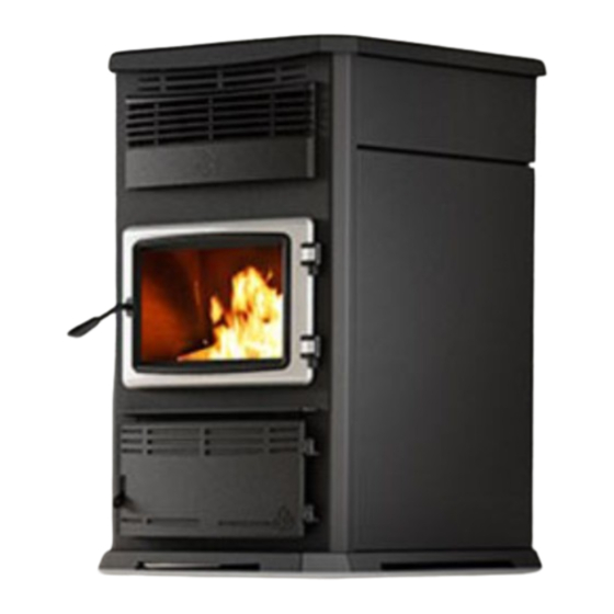
Euromax
(EP00070 model)
CONTACT LOCAL BUILDING OR FIRE OFFICIALS ABOUT RESTRICTIONS AND INSTALLATION
INSPECTION REQUIREMENTS IN YOUR AREA.
PLEASE READ THIS ENTIRE MANUAL BEFORE INSTALLATION AND USE OF THIS PELLET FUEL-
BURNING ROOM HEATER. FAILURE TO FOLLOW THESE INSTRUCTIONS COULD RESULT IN
PROPERTY DAMAGE, BODILY INJURY OR EVEN DEATH.
READ AND KEEP THIS MANUAL FOR REFERENCE
This manual is available for free download on the manufacturer's web site. It is a copyrighted
document. Re-sale is strictly prohibited. The manufacturer may update this manual from time to time
and cannot be responsible for problems, injuries, or damages arising out of the use of information
contained in any manual obtained from unauthorized sources.
Printed in Canada
INSTALLATION
AND OPERATION
MANUAL
INSTALLATION BY A
PROFESSIONAL IS STRONGLY
RECOMMENDED
Safety tested according to ULC S627,
UL1482 and ASTM E1509
by an accredited laboratory.
www.enerzone-intl.com
Stove Builder International Inc.
250, rue de Copenhague,
St-Augustin-de-Desmaures (Quebec)
Canada G3A 2H3
After-sale service: 418 908-8002
E-mail:
tech@sbi-international.com
45724A
05-05-2016
Advertisement
Table of Contents

Related Manuals for Enerzone Euromax EP00070


Summary of Contents for Enerzone Euromax EP00070
- Page 1 Euromax PROFESSIONAL IS STRONGLY (EP00070 model) RECOMMENDED Safety tested according to ULC S627, UL1482 and ASTM E1509 by an accredited laboratory. www.enerzone-intl.com Stove Builder International Inc. 250, rue de Copenhague, St-Augustin-de-Desmaures (Quebec) Canada G3A 2H3 After-sale service: 418 908-8002 E-mail: tech@sbi-international.com...
- Page 2 THANK YOU FOR CHOOSING THIS ENERZONE PELLET STOVE As one of North America’s largest and most respected pellet stove, wood stove and fireplace manufacturers, Stove Builder International takes pride in the quality and performance of all its products. We want to help you get maximum satisfaction as you use this product.
-
Page 3: Table Of Contents
Table of contents INTRODUCTION............................. 5 1.1 About Pellet Heating ........................... 5 1.1.1 Top 10 Reasons for Buying a Pellet Stove ..................5 1.2 Appliance performance ..........................6 1.3 General Features ............................7 1.4 Overall Exterior Dimensions ........................8 PART A – INSTALLATION ............................. 9 Installation Safety Information ........................ - Page 4 APPENDIX D: MOBILE HOME INSTALLATION ....................93 APPENDIX E: COMBUSTION AIR SUPPLY ....................... 95 APPENDIX F: INSTALLING THE OPTIONAL DOOR OVERLAY ............... 98 APPENDIX G: OPTIONAL HOT AIR DISTRIBUTION KIT (AC01343) ............... 99 ENERZONE LIMITED LIFETIME WARRANTY ....................100 Euromax Pellet Stove Installation and Operation Manual...
-
Page 5: Introduction
1 INTRODUCTION 1.1 About Pellet Heating Pellet stoves offer a dramatic improvement in the convenience of heating with solid fuel. Wood pellets are handled in bags and are therefore easily and cleanly stored. A single loading of a pellet stove can provide long hours of warmth. Pellet stoves also provide a special comfort associated with wood burning. -
Page 6: Appliance Performance
1.2 Appliance performance ☨ Fuel type Wood Pellet (Premium grade or better) Recommended heating area 1,000 to 2,800 ft (93 to 260 m Hopper capacity 125 lb (57 kg) Maximum burn time 104 h Maximum heat input rate 70,500 BTU/h (20.6 kW) Overall heat output rate (min. -
Page 7: General Features
1.3 General Features Recommended chimney diameter 4 po (see Section 4.3: Equivalent Vent Length (EVL)) Flue outlet diameter 4 po (100 mm) Type of chimney ULC/ORD-C441, CAN/ULC S609, UL 641 (TYPE L) Baffle material Stainless Steel Approved for alcove installation Not approved Approved for mobile home ‡... -
Page 8: Overall Exterior Dimensions
1.4 Overall Exterior Dimensions FRESH AIR INLET FLUE OUTLET Euromax Pellet Stove Installation and Operation Manual... -
Page 9: Part A - Installation
PART A – INSTALLATION 2 Installation Safety Information 2.1 Installation Warnings, Cautions and Recommendations PROFESSIONNAL INSTALLATION IS HIGHLY RECOMMENDED. YOU MAY NEED TO OBTAIN A BUILDING PERMIT FOR THE INSTALLATION OF THIS STOVE AND ITS VENTING SYSTEM. CONSULT YOUR MUNICIPAL BUILDING DEPARTMENT OR FIRE DEPARTMENT BEFORE INSTALLATION TO DETERMINE THE NEED TO OBTAIN ONE. -
Page 10: Regulations Covering Pellet Stove Installation
DO NOT INSTALL A FLUE DAMPER IN THE EXHAUST VENTING SYSTEM OF THIS UNIT. DO NOT CONNECT THIS STOVE TO ANY OTHER EXISTING VENTING SYSTEM SERVING ANOTHER APPLIANCE. DO NOT CONNECT TO OR USE IN CONJUNCTION WITH ANY AIR DISTRIBUTION DUCTWORK. -
Page 11: Before Operating Your Stove
2.3 Before Operating Your Stove Some minor installation and adjustment are required prior to use: If desired, LCD sliding support can be installed on the left at the back of the stove; (see Appendix B: Repositioning the LCD Sliding Bracket). ... -
Page 12: Clearances To Combustible Material
3 Clearances to Combustible Material The clearances shown in this section have been determined by tests according to procedures set out in safety standards ULC S627 (Canada), ASTM E1509 (U.S.A). When the pellet stove is installed so that its surfaces are at, or beyond, the minimum clearances specified, combustible surfaces will not overheat under normal and even abnormal operating conditions. -
Page 13: Back Wall Installation
3.3 Back Wall Installation For a back wall installation, in order to allow the LCD sliding support to move freely and fully extend, you should allow a minimum of 6″ (152 mm) clearance from the side wall (B) and 3″(80 mm) clearance at the back of the stove, from the fresh air intake (A). -
Page 14: Floor Protection
3.6 Floor Protection For floor protection clearances refer to the following table. FLOOR PROTECTION LETTER CANADA 18″ (457 mm) 6″ (152 mm) N/A (USA only) 6″ (152 mm) 8″ (203 mm) N/A (Canada only) 8″ (203 mm) N/A (Canada only) CAUTION: THE STOVE MUST BE PLACED ON A CONTINUOUS (GROUTED JOINTS) NONCOMBUSTIBLE MATERIAL SUCH AS CERAMIC TILE*, CEMENT BOARD, BRICK, MILLBOARD OR EQUIVALENT, OR ANY OTHER APPROVED OR LISTED MATERIAL... -
Page 15: Venting System
4 Venting system 4.1 General Even though the chimney draft is mechanical, a suitable venting system will ensure a natural draft which will prevent smoke spillage in your home if a power outage occurs. Moreover, a suitable venting system configuration will help getting the best efficiency out of your stove when installed in accordance with the required EVL (see Section 4.3 Equivalent Vent Length (EVL)). - Page 16 Here is an example to help you calculate Equivalent Vent Length. On the following figure the EVL can be calculated like this: 2 horizontal run of 1’ = (2 X 1’) X 1’ = 2’ of EVL 1 elbow 90° or "Tee" = 5’ of EVL ...
-
Page 17: Termination Location
4.4 Termination Location Termination should not be located so that hot exhaust gases can be a hazard. They can reach temperatures of 500°F (260°C) and cause serious burns. CAUTION: TERMINATION COLLAR (SPARK ARRESTER) IS MANDATORY. 4.4.1 Permitted Termination Location Refer to NFPA 211 (USA) or CSA B365 (Canada) for rules for the distance of exit terminal from windows and openings. - Page 18 Canada: Min. Letter Description clearances Clearances above grade level or any adjacent surface that might 12’’ (30 cm) support snow, ice, or debris 39’’ (100 cm) Clearance to window or door that may be opened 39’’ (100 cm) Clearance to corner or adjacent wall Not to be installed above a meter/regulator assembly within 39"...
-
Page 19: Installation Configurations
4.5 Installation Configurations 4.5.1 Installation Warnings, Cautions and Recommendations Reminder PROFESSIONNAL INSTALLATION IS HIGHLY RECOMMENDED THIS STOVE USES A PRESSURIZED VENTING SYSTEM. ALL VENT CONNECTOR JOINTS MUST BE SEALED AND FASTENED. CONSULT THE PELLET VENT MANUFACTURER’S INSTRUCTION TO ENSURE PROPER INSTALLATION, CONSISTENT PERFORMANCE, AND TO AVOID SMOKE AND ASH SPILLAGE. -
Page 20: Through Roof Installation
CAUTION: TO REDUCE THE RISK OF SMOKE SPILLAGE THERE SHOULD ALWAYS BE AT LEAST 12" (30 CM) OF VERTICAL RISE FOR EACH FOOT OF HORIZONTAL RUN. IN ALL CASES, AT LEAST 36" (91 CM) OF VERTICAL RISE IS NEEDED BEFORE THE TERMINATION. -
Page 21: Through A Factory Built Chimney
4.5.4 Through a Factory Built Chimney To make an installation through a factory built chimney, run a 4" stainless steel liner inside the factory built chimney. 1. Position stove following clearances given Section Minimum Clearances Combustibles following vent manufacturer’s instructions. 2. -
Page 22: Through An Existing Masonry Fireplace
4.5.5 Through an Existing Masonry Fireplace 1. Position stove, following clearances shown Section Minimum 12”-18” Clearances Combustibles following vent manufacturer’s instructions. 2. Build and Install a blocking plate inside the chimney to seal the fireplace damper. Stainless steel plate screws are recommended. Cut a hole for the exhaust pipe. -
Page 23: Through An Existing Masonry Chimney
4.5.6 Through an Existing Masonry Chimney 1. Position stove following clearances shown Section Minimum 12”-18” Clearances Combustibles following vent manufacturer’s instructions. 2. Mark the center of the hole where the vent pipe will go through the masonry chimney. 3. It is necessary to make a hole in the masonry with a one-inch diameter greater than the diameter of the vent pipe used. -
Page 24: Part B - Operation
PART B - OPERATION 5 General information 5.1 Operation Warnings, Cautions and Recommendations KEEP THIS MANUAL FOR REFERENCE. DURING THE FIRST FEW FIRES, YOUR STOVE WILL EMIT AN ODOR AND A SMALL AMOUNT OF FUMES AS THE HIGH TEMPERATURE PAINT CURES OR BECOMES SEASONED TO THE METAL. - Page 25 NEVER TRY TO REPAIR OR REPLACE ANY PART OF THE STOVE UNLESS INSTRUCTIONS ARE GIVEN BY THE MANUFACTURER. ALL OTHER WORK SHOULD BE DONE BY A TRAINED TECHNICIAN. DO NOT OPERATE THE STOVE IF THE FLAME BECOMES DARK AND SOOTY OR IF THE BURN POT OVERFILLS WITH PELLETS.
-
Page 26: Zone Heating And How To Make It Work For You
THIS STOVE IS DESIGNED TO PROVIDE THE OPTIMUM PROPORTIONS OF FUEL AND AIR TO THE FIRE IN ORDER TO BURN FREE OF SMOKE AND SOOT. ANY BLOCKAGE OF THE AIR SUPPLY TO OR FROM THE STOVE WILL SERIOUSLY DECREASE ITS PERFORMANCE AND WILL BE EVIDENT BY A SMOKING EXHAUST, A SOOT BUILDUP ON THE WINDOW AND ON OUTSIDE WALLS. -
Page 27: Combustible
Although the stove may be able to heat the main living areas of your house to an adequate temperature, this stove must serve as a supplementary heat source. You should have a conventional oil, gas or electric additional heating system to provide heating in the home. The manufacturer cannot be responsible for additional heating costs associated with the use of an alternative heat source in case of stove failure or power outage. -
Page 28: Stove Controls
6 Stove controls 6.1 General Information The stove uses a LCD touch screen, the latest technology in control devices. The blowers and feed system are controlled from this screen. The LCD touch screen is preassembled and ready to be installed on the right hand side of the stove when facing it. - Page 29 Description of each main status page icon: Operating mode Thermostatic (Thermostat mode calling or manual) for heat Settings button Burn rate parameters Feed screw On/Off button button FEED AND START Burn rate Feed screw adjustment parameters PURGE SCREW Convection blower speed adjustment STOP Feed screw...
-
Page 30: Configuration And Operation Diagram
6.1.2 Configuration and Operation Diagram Access to program VX.XX(X ) VX.XX X:XX:XX XX°F XX°F Demo mode Allows to slightly adjust of the unit the combustion and pilot parameters 6.1.3 Selecting the Language and Temperature Unit (⁰F or ⁰C) From the main status page, choose the settings icon . -
Page 31: Adjusting The Combustion Level (Heat Output)
6.1.5 Adjusting the Combustion Level (Heat Output) Press on the pellet burn rate adjustment button Press + or - to adjust the burn rate The stove’s input range goes from 10,500 BTU to 70,000 BTU. To change combustion level, on the main status page to display the “+” and “-” combustion level select the flame icon settings. -
Page 32: Combustion Settings And Pilot Settings Depending On Fuel Quality
6.1.6 Combustion Settings and Pilot Settings depending on Fuel Quality 6.1.6.1 PILOT ADJUSTMENT (Pilot Settings Adjustment) The “PILOT ADJUSTEMENT” will allow you to modify default settings by ±5% for auger motor 1 and ±10% for combustion and exhaust fan, but will only apply during pilot cycle: To restore default setting, select “DEFAULT”. -
Page 33: Convection Fan Speed Adjustment
Average speed of auger motor #1: You may want to increase the auger motor #1 speed if fire goes out when combustion level is at its minimum setting. When burning poor quality pellets you may also need to reduce the auger motor speed to avoid unburned pellets to fall into the ash drawer at any combustion level. -
Page 34: Selecting Manual Or Thermostat Mode
6.1.8 Selecting Manual or Thermostat Mode To change operating mode, press the desired mode from the Main Status Page. Operating mode (Thermostat or manual) Press on the desired mode Indicates that the stove is in manual mode. It will therefore run continuously on the selected setting until it is manually modified, turned OFF or if the stove runs out of pellets. -
Page 35: Selecting The Pilot Cycle
6.1.9 Selecting the Pilot Cycle To change the pilot cycle press the word “AUTO” from the Main Status Page. You can choose from one of the four different pilot cycles: "ALWAYS ON", "30 MINUTES", “60 MINUTES”, or "ALWAYS OFF". The selected cycle will be displayed under the word “AUTO” on the main status page. -
Page 36: Filling Or Purging Auger Housing
6.1.10 Filling or Purging Auger Housing Note: This function is disabled when the stove is running. and select either “FEED AND To fill or purge the auger housing press the auger icon START” or “PURGE SCREW” in the displayed page. Feed screw FEED AND START parameters... -
Page 37: Demo Mode
6.1.11 Demo Mode 6.1.11.1 Demo Mode Operation The demo mode has been developed primarily to enable sales people to show the stove's functionalities in showrooms without starting it. Thus, when the "DEMO" mode is activated, the stove will not turn on but all the components will operate as if the stove was on. To disable the "DEMO"... -
Page 38: Stove Operation
7 Stove operation 7.1 First Startup Before starting your stove, make sure that the burn pot, the baffles and the maintenance access panels are properly installed. Make sure that the stove has been emptied of all tools and accessories (see Section 2.3: Before Operating Your Stove). Also make sure that the venting system is properly sealed, that all doors and hopper lid are closed. -
Page 39: Shutting Down Procedure
7.5 Shutting Down Procedure To turn your stove off, press the “ON/OFF” icon on the Main Status Page. The cooling cycle will take a few minutes and the blowers will continue to function while the stove is cooling down. IMPORTANT: DO NOT DISCONNECT THE POWER CORD TO TURN OFF THE STOVE. 7.6 Signs of an Overheating Stove Under normal conditions, the flame should have a bright yellow color and be very active, but stable. -
Page 40: Maintenance
8 Maintenance 8.1 Stove Maintenance 8.1.1 Recommended Maintenance Schedule Use this as a guide when used under average conditions. Weekly Twice a year Annually Components or after or after ± 250 pounds ± 1 tons ± 2 tons Baffle Vacuum Bottom airwash inlet Vacuum Burn Pot... -
Page 41: Cleaning The Baffle, The Heat Exchanger And The Combustion Chamber
8.1.2 Cleaning the Baffle, the Heat Exchanger and the Combustion Chamber Cleaning of the heat exchanger must be done on a regular basis (see Section 8.1.1: Recommended Maintenance Schedule). To access the heat exchanger you need to first rise up and pull towards you the decorative grill (A) above the viewing door. Unscrew the two wing nuts (B) and remove the access panel (C) to the heat exchangers. - Page 42 DO NOT USE PLIERS OR OTHER TOOLS TO TIGHTEN THE WING NUTS. To clean the baffle, pivot the lock plate (A) by 90° found above the access door of the combustion chamber. The baffle (B) will rotate and drop the accumulated fly ash. Clean and reinstall the baffle.
-
Page 43: Exhaust Channel And Exhaust Blower Maintenance
8.1.3 Exhaust Channel and Exhaust Blower Maintenance Exhaust channels and the exhaust blower are located on the left hand side of the stove. The following procedure demonstrates how to perform inspection and cleaning: In order to access the exhaust channels, open the left side decorative panels. Using a Philips or Robertson screwdriver, remove both clean-out traps by unlocking them. - Page 44 Make sure that the gaskets are still in good condition, replace them if needed. (3/16’’ black round gasket) Euromax Pellet Stove Installation and Operation Manual...
-
Page 45: Cleaning The Burn Pot
8.1.4 Cleaning the Burn Pot The burn pot must remain clean and the holes should not be obstructed by combustion residues (ashes or clinkers). 1. Clean the burn pot using the scraper provided with the stove or a smaller one. 2. - Page 46 3. If necessary, clean the air intake channel. To reach the air intake channel clean out trap, open the ash drawer access door and remove the ash drawer (A). Euromax Pellet Stove Installation and Operation Manual...
- Page 47 4. Unscrew the wing nut (D) to open the clean out trap (E). Vacuum the combustion residues. 5. Verify that the clean out trap gasket is still in good condition; replace it if needed (3/16’’ black round gasket (AC06815). Euromax Pellet Stove Installation and Operation Manual...
-
Page 48: Ash Removal
8.1.5 Ash Removal 1. To empty the ash drawer (A) of its contents, open the ash pan access door by lifting the latch on the right hand side. 2. Vacuum around the ash drawer and at the bottom of the combustion chamber. WARNING: ASH PAN MUST BE IN PLACE AND THE ASH PAN ACCESS DOOR MUST BE KEPT CLOSED AT ALL TIMES WHEN THE STOVE IS IN USE. -
Page 49: Cleaning The Air Wash System
8.1.6 Cleaning the Air Wash System Vacuum the ashes that may have accumulated into the airwash system inlet between the bottom glass retainer and the glass. This will allow an optimum air flow along the inside portion of the glass and prevents the glass from sooting-up. 8.1.7 Glass Care Clean door glass when necessary. -
Page 50: Door Gasket Maintenance
8.1.9 Door Gasket Maintenance It is important to maintain the door gasket in good condition. After a while, the gasket will wear and compress; adjusting the door may then be required. If the door adjustment is not sufficient, replace the door gasket with a genuine part. If the stove door is not properly sealed, it will be difficult to keep the door glass clean and combustion gases may leak into the room. -
Page 51: Dealing With A Chimney Fire
8.2.1 Dealing With a Chimney Fire Regular chimney maintenance and inspection can prevent chimney fires. If you have a chimney fire, follow these steps: 1. Alert your family of a possible danger. 2. If you need assistance, call the fire department; 3. -
Page 52: Troubleshooting
9 Troubleshooting When you have issues with your stove, your first reaction may be to call technical support. This section will help you save time and money by enabling you to solve simple problems by yourself. Most common problems are generally caused by the following five factors: 1. - Page 53 To validate the status of a component, you need to go to the “TROUBLESHOOT” page from the Main Status Page. Once there you will be able to navigate with the arrows through 7 different pages. Access to program VX.XX(X ) VX.XX X:XX:X XX°F XX°F...
-
Page 54: Testing Components
9.2 Testing Components If you suspect an electrical component to be defective, you can test it from the “TROUBLESHOOT” page. From the Main Status Page, press the Settings icon choose “TROUBLESHOOT” in the menu. Page 5 and 6 will allow you to test every electrical component. -
Page 55: Blocked Flue
9.3.1 Blocked Flue o Pressure tap (located on the exhaust blower) is blocked. Pull off the air hose from the exhaust blower pressure tap and from the negative (white) pressure switch tap. WARMING: THE TUBE MUST ABSOLUTELY BE DISCONNECTED FROM BOTH ENDS AS TO NOT DAMAGE THE PRESSURE SWITCH. -
Page 56: No Fuel
9.3.2 No Fuel The stove ran out of pellets. Refill the hopper. Press “Reset” then “Feed and Start” (see Section 6.1.10: Filling or Purging Auger Housing). The burn pot holes are blocked. Remove the burn pot and clean it thoroughly. ... - Page 57 BURN POT AUGER Screws Auger and motor assembly Gasket NOTE: IF THE HOPPER AUGER MOTOR FAILED OR THE HOPPER AUGER IS JAMMED, TO AVOID PELLET SPILLAGE, EMPTY THE HOPPER OF ITS CONTENTS BEFORE EXECUTING THE FOLLOWING TESTS. o If the auger motor is defective, check to make sure that electrical connections are not loose and check the fuses F2 and F6 on the control board.
-
Page 58: Failed Ignition
9.3.3 Failed Ignition Inadequate fuel is used. Remove the burn pot, make sure that all openings are clear and check that no ash has filled the tube around the igniter. Refer to the maintenance section. Also, make sure that recommended fuel is used (see Section 5.2.1 Proper Fuel). ... -
Page 59: Auger Fuse
The igniter is defective: Test the resistance (ohms, Ω) with a multimeter. If the value is near zero, replace the igniter and the F3 fuse. The wiring harness shorted. Inspect the wiring and replace any defective wire and or connector. -
Page 60: Unit Overheat
9.3.6 Unit Overheat Inadequate fuel is used. Remove the burn pot, make sure that all openings are clear and check that no ash has filled the tube around the igniter. Refer to the maintenance section. Also, make sure that the recommended fuel is used (see Section 5.2.1 Proper Fuel). ... -
Page 61: Hopper Lid Open
ONCE THE MAINTENANCE DONE, FOLLOW THESE INSTRUCTIONS After 3 attempts press restart and then enter the following code 999333555 and press accept. The system will reset. 9.3.7 Hopper Lid Open The hopper lid remained open for more than 3 minutes. As a security measure, the auger stops turning and feeding pellets as soon as the hopper lid opens. -
Page 62: Smoke Smell
Power was interrupted while the stove was functioning. After the cool down cycle, the stove will restart using the last settings. Press “RESET” to go back to the Main Status Page. Note: For a short power failure (less than 5 seconds), the stove will continue to function at the selected speed. -
Page 63: Combustion Air Starvation
9.3.10 Combustion Air Starvation Venting system is dirty. Refer to Section 8: Maintenance. The flue is not properly installed. Make certain the venting system meets the criteria in the installation section of this manual as well as the venting system manufacturer’s instructions. -
Page 64: Wiring Diagram
10 Wiring Diagram Euromax Pellet Stove Installation and Operation Manual... -
Page 65: Access To Fuses
11 Access to Fuses WARNING: UNPLUG THE STOVE BEFORE CHANGING THE FUSES. All fuses are located inside the housing of the electronic board; the housing is on the back of your stove. Unplug your stove, remove the screw and turn the four spring clips to open the housing. - Page 66 LETTER FUSE FUNCTION AMPERAGE MAIN BOARD FUSE 7.5A CONVECTION BLOWER COMBUSTION BLOWER EXHAUST BLOWER TOP AUGER #1 BOTTOM AUGER #2 IGNITOR Euromax Pellet Stove Installation and Operation Manual...
-
Page 67: Components Location
12 Components location LETTER COMPONENT HEAT EXCHANGER TUBES BURN POT IGNITOR CONVECTION BLOWER THERMISTOR L-250 THERMAL SWITCH HOPPER TOUCH SCREEN CONTROL PANEL HOPPER SAFETY SWITCH PRESSURE SWITCH F-160 THERMAL SWITCH POWER CORD RECEPTACLE THERMOSTAT TERMINAL BLOCK COMBUSTION BLOWER/FRESH AIR INTAKE EXHAUST BLOWER BOTTOM AUGER #2 TOP AUGER #1... -
Page 68: Blower Replacement
13 Blower Replacement CONVECTION BLOWER Before disconnecting the wire harness from the convection fan assembly, take note of which wire goes where. Unscrew screw (A) with a screwdriver (1). Pull downwards on the convection fan and slide out for complete removal (2). Euromax Pellet Stove Installation and Operation Manual... - Page 69 COMBUSTION BLOWER Remove the 9 screws (A) and the bottom grille (B). Unlatch the clamps (C). Remove the backdraft shutter (G) and the gasket (D). Pull the combustion blower (F) and unplug the wire connector from the harness. Remove the plug (E) of the blower.
- Page 70 EXHAUST BLOWER Remove the left panel. Unplug the connections (A) and (B). Unplug the silicone tube (C). Euromax Pellet Stove Installation and Operation Manual...
- Page 71 Remove the clamp (D). With a Philips screwdriver, unlock and remove the access panel (E). Euromax Pellet Stove Installation and Operation Manual...
- Page 72 Remove the nuts (F) located in the opening of the trapdoor. Remove the duct assembly (G). Euromax Pellet Stove Installation and Operation Manual...
- Page 73 Remove the bolts (H) and nuts (I) to remove the exhaust blower (J) Euromax Pellet Stove Installation and Operation Manual...
-
Page 74: 250 And F-160 Thermal Switch Replacement
14 L-250 and F-160 Thermal Switch Replacement L-250 1. Remove both retaining screws (A) holding the thermal switch support bracket (B). 2. Lift up the support bracket. Rotate the bracket 90° clockwise then pull the bracket toward you. Euromax Pellet Stove Installation and Operation Manual... - Page 75 Remove the faulty thermal switch. Replace new thermal switch (D) underneath the bracket (B) by means of 2 screws (C). F-160 Unscrew both screws (B) and take out the thermal switch F-160 (A). Euromax Pellet Stove Installation and Operation Manual...
-
Page 76: Exploded View And Replacement Parts
15 Exploded View and Replacement Parts SECTION A Euromax Pellet Stove Installation and Operation Manual... - Page 77 SECTION B Euromax Pellet Stove Installation and Operation Manual...
- Page 78 SECTION C Euromax Pellet Stove Installation and Operation Manual...
- Page 79 SECTION D SECTION E Euromax Pellet Stove Installation and Operation Manual...
- Page 80 SECTION F SECTION G Euromax Pellet Stove Installation and Operation Manual...
- Page 81 SECTION H SECTION I Euromax Pellet Stove Installation and Operation Manual...
- Page 82 SECTION J SECTION K Euromax Pellet Stove Installation and Operation Manual...
- Page 83 IMPORTANT: THIS IS DATED INFORMATION. When requesting service or replacement parts for your stove, please provide the model number and the serial number. We reserve the right to change parts due to technology upgrade or availability. Contact an authorized dealer to obtain any of these parts.
- Page 84 Item Description 30029 CUTTING THREAD SCREW 10-24 TYPE "F" X 3/8" HEX WASHER PL67173 BAFFLE EXTENSION SE24230 ASH DRAWER ACCESS DOOR WITH HANDLE AND GASKET PL64339 LATCH GUIDE OF THE DRAWER DOOR 30187 ZINC WASHER ID 17/64" X OD 1/2" 30093 BOLT 1/4-20 X 3/4"...
- Page 85 Item Description PL64357 MOTHER BOARD 6 OUPUT 44013 FUSE 7.5A / 250V / 1/4" DIA. X 1 1/4''L 44015 FUSE 5A / 250V / 1/4" DIA. X 1 1/4''L 44016 FUSE 3A / 250V / 1/4" DIA. X 1 1/4''L 30132 SCREW #10 X 3/8"...
-
Page 86: Appendix A: Horizontal And Vertical Vent Chart
APPENDIX A: HORIZONTAL AND VERTICAL VENT CHART Possible Horizontal vent length (feet) For example, let’s imagine an installation consisting of a horizontal vent coming out at the back of the stove on a total distance of 8 feet. This horizontal run is followed by a tee and a 6-foot vertical rise. This type of installation is not acceptable. - Page 87 Instead, if the installation consisted of a horizontal vent coming out at the back of the stove on a total distance of 4 feet, followed by a tee and a 6-foot vertical rise, it would be acceptable. The termination is within the allowable configuration zone on the chart since it would have at least one foot of vertical rise for each foot of horizontal run.
-
Page 88: Appendix B: Lcd Sliding Bracket
APPENDIX B: LCD SLIDING BRACKET The LCD sliding bracket is preassembled on the right hand side, when facing the stove, but can be installed on the opposite side. Lowering the mounting bracket will be necessary if the hot air distribution kit is to be installed (see position #2). Step 1 To reverse the assembly to a left side configuration, extend the rail with the LCD support (A) in order to gain access to the two screws (B). - Page 89 Step 3 Take the Telco black wire (E) which is located on the rear bottom panel and plug it into the back of the LCD touch screen interface receptacle. Then, secure the LCD touch screen housing (F) on the rail (A). Euromax Pellet Stove Installation and Operation Manual...
-
Page 90: Appendix C: Installing A Thermostat (Ac05558)
APPENDIX C: INSTALLING A THERMOSTAT (AC05558) Using a thermostat will help you maintain a constant temperature throughout the house. A low voltage thermostat (24 volts) is required. A fixed wall mount or hand held model can be used. Note: Thermostat manufacturer’s instructions always override the information published in the following section. - Page 91 Before installing the thermostat, unplug the power cord from the power outlet. First, connect the two thermostat wires to the terminal block located at the rear on the right hand side of the stove when facing it. Loosen the two middle screws and insert the wires in the terminals.
- Page 92 Wireless thermostat If you are using a wireless thermostat or a hand held thermostatic remote control, connect the two thermostat wires to the terminal block located at the rear on the right hand side of the stove while facing it. If the receiver wires are equipped with quick-connect terminals you can connect them directly to the stove’s wiring harness.
-
Page 93: Appendix D: Mobile Home Installation
APPENDIX D: MOBILE HOME INSTALLATION Anchor the stove WARNING: FOR MOBILE HOME INSTALLATION, IT IS MANDATORY TO CONNECT THE STOVE TO AN OUTSIDE COMBUSTION AIR SOURCE. (SEE APPENDIX E) When installed in a mobile home, the stove must be anchored to the floor with two screws. Use the two anchoring holes (A) located for this purpose on each side of the pedestal, as shown on the following image. - Page 94 Fresh air intake Pellet pipe length and/or slip section Ceiling support Attic insulation shield Roof flashing Storm collar Pellet pipe length Vertical rain cap Euromax Pellet Stove Installation and Operation Manual...
-
Page 95: Appendix E: Combustion Air Supply
APPENDIX E: COMBUSTION AIR SUPPLY WARNING: FOR MOBILE HOME INSTALLATION, IT IS MANDATORY TO CONNECT THE STOVE TO AN OUTSIDE COMBUSTION AIR SOURCE. INSULATED PIPE SHOULD NEVER EXCEED 10 FEET. It is recommended to install an outside air inlet in or near the room where the stove is installed. - Page 96 To complete the installation, make a hole of1/4" to 1/2" (6 mm à 13 mm) bigger than the insulate pipe diameter in the outside wall of the house at the chosen location. From outside, place the outside air inlet cap (E) in the hole (open side down) and fasten the register to the wall, with screw.
- Page 97 Sources of Outside Combustion Air WARNING: IT IS FORBIDDEN TO DRAW COMBUSTION AIR FROM A BASEMENT, AN ATTIC, A GARAGE OR ANY CONFINED SPACE. You can draw air from a ventilated crawl space underneath the floor. You can draw air directly from an outside wall, behind the stove. Euromax Pellet Stove Installation and Operation Manual...
-
Page 98: Appendix F: Installing The Optional Door Overlay
APPENDIX F: INSTALLING THE OPTIONAL DOOR OVERLAY In order to complete the assembly of your Enerzone Euromax, you need to install the door overlay (A). See figure below for installation instructions: 1- Position the overlay (A) on the door frame and secure it in place from behind using the 4 screws (B). -
Page 99: Appendix G: Optional Hot Air Distribution Kit (Ac01343)
APPENDIX G: OPTIONAL HOT AIR DISTRIBUTION KIT (AC01343) *** The hot air distribution kit for Enerzone Euromax will be available soon. Call your local dealer for more detail. *** This is an example only. Hot air distribution kit may differ. -
Page 100: Enerzone Limited Lifetime Warranty
Proof of purchase (dated bill of sale), model name and serial number must be supplied when making any warranty claim to your ENERZONE dealer.
Need help?
Do you have a question about the Euromax EP00070 and is the answer not in the manual?
Questions and answers