Table of Contents
Advertisement
Quick Links
INSTALLATION
AND OPERATION
MANUAL
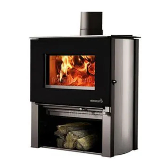
Destination 1.6
(EB00025 model)
US ENVIRONMENTAL PROTECTION
AGENCY PHASE II CERTIFIED WOOD
STOVE
www.enerzone-intl.com
Safety tested according to ULC S627, UL 737
Stove Builder International Inc.
and UL 1482 Standards by
250, rue de Copenhague,
an accredited laboratory
St-Augustin-de-Desmoures
(Quebec) Canada G3A 2H3
After-sale service: 418-908-8002
E-mail: tech@sbi-international.com
READ AND KEEP THIS MANUAL FOR REFERENCE
This manual is available for free download on the manufacturer's web site. It is a
copyrighted document. Re-sale is strictly prohibited. The manufacturer may update this
manual from time to time and cannot be responsible for problems, injuries, or damages
arising out of the use of information contained in any manual obtained from unauthorized
sources.
45750A
Printed in Canada
02-09-2015
Advertisement
Table of Contents

Related Manuals for Enerzone EB00025


Summary of Contents for Enerzone EB00025
- Page 1 INSTALLATION AND OPERATION MANUAL Destination 1.6 (EB00025 model) US ENVIRONMENTAL PROTECTION AGENCY PHASE II CERTIFIED WOOD STOVE www.enerzone-intl.com Safety tested according to ULC S627, UL 737 Stove Builder International Inc. and UL 1482 Standards by 250, rue de Copenhague, an accredited laboratory...
- Page 2 THANK YOU FOR CHOOSING THIS ENERZONE WOOD STOVE As one of North America’s largest and most respected wood stove and fireplace manufacturers, Stove Builder International takes pride in the quality and performance of all its products. We want to help you get maximum satisfaction as you use this product.
-
Page 3: Table Of Contents
Table of content PART A - OPERATION AND MAINTENANCE ....... 6 1 Safety Information ..............6 Summary of Operation and Maintenance Cautions and Warnings ........6 2 General Information ..............7 Destination 1.6 Specifications ................... 7 Zone Heating and How to Make it Work for You .............. 10 The Benefits of Low Emissions and High Efficiency ............ - Page 4 5 Maintaining Your Wood Heating System ....... 23 Stove Maintenance ......................23 5.1.1 Cleaning Door Glass ....................23 5.1.2 Door adjustment ......................24 5.1.3 Replacing the Door Gasket ..................26 5.1.4 Replacing the Glass Gasket and/or the Glass .............. 27 5.1.5 Cleaning and Painting the Stove ..................
- Page 5 Appendix 3: Installation and Use of the Optional Blower and Thermodisc ............... 49 Appendix 4: Installation of Secondary Air Tubes and Baffle ... 51 Appendix 5: Exploded Diagram and Parts List ......53 ENERZONE LIMITED LIFETIME WARRANTY ......56 Destination 1.6 Installation and Operation Manual...
-
Page 6: Part A - Operation And Maintenance
PART A - OPERATION AND MAINTENANCE Please see Part B for installation instructions. 1 Safety Information 1.1 Summary of Operation and Maintenance Cautions and Warnings • HOT WHILE IN OPERATION, KEEP CHILDREN, CLOTHING AND FURNITURE AWAY. CONTACT MAY CAUSE SKIN BURNS. GLOVES MAY BE NEEDED FOR STOVE OPERATION. -
Page 7: General Information
General Information 2.1 Destination 1.6 Specifications Fuel Type Dry cordwood Test Standards (safety) ULC S627, UL 737 and UL 1482 Test Standard (emissions) EPA Method 28 (40 CFR Part 60) Heating capacity range* 500 to 1,500 sq. ft. (47 to 139 m Maximum heat output** 23 275 BTU/h (6,8 kW/h) (EPA test fuel) - Page 8 Destination 1.6 Installation and Operation Manual...
- Page 9 Destination 1.6 Installation and Operation Manual...
-
Page 10: Zone Heating And How To Make It Work For You
2.2 Zone Heating and How to Make it Work for You Your new Destination 1.6 wood stove is a space heater, which means it is intended to heat the area it is installed in, as well as spaces that connect to that area, although to a lower temperature. This is called zone heating and it is an increasingly popular way to heat homes or spaces within homes. - Page 11 The C-Cast baffle is made of an aluminosilicate fibre material that is compressed with a binder to form a rigid board. C-Cast can withstand temperatures above 2,000 °F. It is not considered hazardous waste. Disposal at a landfill is recommended. Firebrick is mainly composed of silicon dioxide, also known as silica, an earth derived product.
-
Page 12: Fuel
3 Fuel 3.1 Materials That Should Not be Burned • GARBAGE OF ANY KIND, • COAL OR CHARCOAL, • TREATED, PAINTED OR COATED WOOD, • PLYWOOD OR PARTICLE BOARD, • FINE PAPER, COLORED PAPER OR CARDBOARD, • SALT WATER DRIFTWOOD •... -
Page 13: Log Length
3.2.3 Log Length Logs should be cut about 1” (25 mm) shorter than the firebox so they fit in easily. Pieces that are even slightly too long make loading the stove very difficult. The most common standard length of firewood is 16” (400 mm). The pieces should be a consistent length, with a maximum of 1”... -
Page 14: How To Dry Firewood
3.2.5 How to Dry Firewood Firewood that is not dry enough to burn is the cause of most complaints about wood stoves. The complaints usually involve a lack of heat and dirty door glass. Here are some things to consider in estimating drying time: •... -
Page 15: Where To Store Wood
3.2.6 Where to store wood This stove has been certified to store logs in the pedestal provided that the following requirements are met: • The logs must not exceed the inside edge (A) of the pedestal. • The heat shield baffle (B) under the firebox must never be removed. -
Page 16: Manufactured Logs
3.3 Manufactured Logs Do not burn manufactured logs made of wax impregnated sawdust or logs with any chemical additives. Manufactured logs made of 100% compressed sawdust can be burned, but use caution in the number of these logs burned at one time. Start with one manufactured log and see how the stove reacts. -
Page 17: Operating Your Stove
4 Operating Your Stove 4.1 Your First Fires Two things will happen as you burn your first few fires; the paint cures and the internal components of the stove are conditioned. As the paint cures, some of the chemicals vaporize. The vapors are not poisonous, but they do smell bad. -
Page 18: The Top Down Fire
4.2.2 The Top Down Fire The top down fire starting method solves two problems with the conventional method: first, it does not collapse and smother itself as it burns; and second, it is not necessary to build up the fire gradually because the firebox is loaded before the fire is lit. -
Page 19: Ash Removal
When you burn in cycles, you rarely need to open the stove’s loading door while the wood is flaming. This is an advantage because there is more chance that smoke will leak from the stove when the door is opened as a full fire is burning. This is especially true if the chimney connector has 90°... -
Page 20: Firing Each New Load Hot
4.3.4 Firing Each New Load Hot Place the new load of wood on and behind the charcoal, and not too close to the glass. Close the door and open the air control fully. Leave the air control fully open until the firebox is full of flames, the wood has charred to black and its edges are glowing red. -
Page 21: Building Different Fires For Different Needs
4.3.6 Building Different Fires for Different Needs Using the air control is not the only way to match the stove’s heat output to the heat demand. Your house will need far less heat in October than in January to be kept at a comfortable temperature. If you fill the firebox full in fall weather, you will either overheat the space or turn the stove down so much that the fire will be smoky and inefficient. - Page 22 4.3.6.4 Maximum Burn Cycle Times The burn cycle time is the period between loading wood on a coal bed and the consumption of that wood back to a coal bed of the same size. The flaming phase of the fire lasts for roughly the first half of the burn cycle and the second half is the coal bed phase during which there is little or no flame.
-
Page 23: Maintaining Your Wood Heating System
5 Maintaining Your Wood Heating System 5.1 Stove Maintenance Your new stove will give many years of reliable service if you use and maintain it correctly. Some of the internal components of the firebox, such as firebricks, baffles and air tubes, will wear over time under intense heat. -
Page 24: Door Adjustment
5.1.2 Door adjustment In order for your stove to burn at its best efficiency, the door must provide a perfect seal with the firebox. Therefore, the gasket should be inspected periodically making sure to obtain an air tight fit. Airtightness can be improved with a simple latch mechanism adjustment. 1. - Page 25 3. Unscrew and remove the pillar (C) and (D). 4. Unscrew and remove the decorative side pannel (E). Destination 1.6 Installation and Operation Manual...
-
Page 26: Replacing The Door Gasket
5. To adjust door tightness, slightly loosen the bolts (F). The more distant from the door is the mechanism, the stronger the tightening will 5.1.3 Replacing the Door Gasket It is important to maintain the door gasket (D) in good condition. After a year or more of use, the door gasket will compress and become hard, which may allow air to leak past it. -
Page 27: Replacing The Glass Gasket And/Or The Glass
5.1.4 Replacing the Glass Gasket and/or the Glass It is a good idea to replace the glass gasket when the door gasket is replaced. The gasket is flat, adhesive-backed, woven fibreglass. To replace the glass, follow these steps: 1. Remove the door from its hinges and lay it on a flat and soft surface. 2. - Page 28 The glass gaskets (A) and (B) must be centred on the top and bottom edges of the glass. To do this easily, peel back a section of the paper covering the adhesive and place the gasket on a table with the adhesive side up. Stick the end of the gasket to the edge of the glass, then press the edge of the glass down onto the gasket, taking care that it is perfectly centred on the gasket.
-
Page 29: Cleaning And Painting The Stove
Apply self-adhesive gasket (C) en following the engraving on the inside of the door frame. Reinstall the glass, being careful to centre the glass carefully in the door. Do not over-tighten the screws. Note that the two main causes of broken door glass are uneven placement in the door and over-tightening of retaining screws. -
Page 30: How Often Should You Clean The Chimney
5.2.2 How Often Should You Clean the Chimney? It is not possible to predict how much or how quickly creosote will form in your chimney. It is important, therefore, to check the build-up in your chimney monthly when getting used to the new stove until you determine the rate of creosote formation. -
Page 31: Part B - Installation
PART B - INSTALLATION 6 Safety Information 6.1 Summary of Installation Cautions and Warnings • THE INFORMATION GIVEN ON THE CERTIFICATION LABEL AFFIXED TO THE APPLIANCE ALWAYS OVERRIDES THE INFORMATION PUBLISHED, IN ANY OTHER MEDIA (OWNER’S MANUAL, CATALOGUES, FLYERS, MAGAZINES AND/OR WEB SITES). •... -
Page 32: Clearances To Combustible Material
7 Clearances to Combustible Material The clearances shown in this section have been determined by test according to procedures set out in safety standards ULC S627 (Canada), UL 1482 (U.S.A.) and UL 737 (U.S.A.). When the stove is installed so that its surfaces are at or beyond the minimum clearances specified, combustible surfaces will not overheat under normal and even abnormal operating conditions. - Page 33 Clearances for mobile homes MOBILE HOME CLEARANCES (DOUBLE WALL PIPE) CANADA 12" (305 mm) 12" (305 mm) 16" (406 mm) 16" (406 mm) 7" (178 mm) 7" (178 mm) 15¾" (406 mm) 15¾" (406 mm) 24¾" (635 mm) 24¾" (635 mm) 16¾"...
-
Page 34: Floor Protector
Clearances to combustible materials and floor protection 7.3 Floor protector Your stove is designed to keep the floor from overheating. It should be placed on a non combustible surface to protect the floor of hot embers that could fall from the stove during loading and maintenance. -
Page 35: Reducing Wall And Ceiling Clearances Safely
7.4 Reducing Wall and Ceiling Clearances Safely It is often desirable to reduce the minimum installation clearances by placing the stove closer to walls so the installation takes up less floor space. You can safely reduce the minimum clearances permanently installing shield between the stove and combustible... - Page 36 Clearances for shield construction Destination 1.6 Installation and Operation Manual...
-
Page 37: Table Of Clearance Reduction Percentages
7.4.2 Table of Clearance Reduction Percentages Clearances may be reduced by these percentages Sides Top % Type of shield and rear % (ceiling) Can/USA Can/USA min. min. Sheet metal, a minimum of 24 gauge (0.61 mm) in thickness , spaced out at least 25 mm (1 in)*... -
Page 38: The Venting System
8 The Venting System 8.1 General The venting system, made up of the chimney and the connecting pipe between the stove and the chimney, acts as the engine that drives your wood heating system. Even the best stove will not function safely and efficiently as intended if it is not connected to a suitable chimney. -
Page 39: Factory-Built Metal Chimneys In Mobile Homes
8.2.2 Factory-built Metal Chimneys in mobile homes For use in a mobile home, this stove is to be connected to a 6” in diameter double wall factory built chimney conforming to CAN/UCL-S629, Standards 650°C Factory-built chimney. The total length of the flue system should be at least 12 feet including elbows, from the top of the stove. -
Page 40: Minimum Chimney Height
8.3 Minimum Chimney Height The top of the chimney should be tall enough above turbulence caused when wind blows against the house and its roof. The chimney must extend at least 1 m (3 ft.) above the highest point of contact with the roof, and at least 60 cm (2 ft.) higher than any roof line or obstacle within a horizontal distance... -
Page 41: Why The Chimney Should Penetrate The Highest Heated Space
8.4.2 Why the chimney should penetrate the highest heated space When it is cold outside, the warm air in the house is buoyant so it tends to rise. This tendency of warm air to rise creates a slight pressure difference in the house. Called ‘stack effect’, it produces a slightly negative pressure low in the house (relative to outside) and a slightly positive pressure zone high in the house. -
Page 42: Air Supply In Conventional Houses
8.5.2 Air Supply in Conventional Houses The safest and most reliable supply of combustion air for your wood stove is from the room in which it is installed. Room air is already preheated so it will not chill the fire, and its availability is not affected by wind pressures on the house. - Page 43 Use 45° elbows where possible, instead of 90° elbows. Destination 1.6 Installation and Operation Manual...
- Page 44 The rules below are based on those found in the CSA B365 installation code. Please carefully follow these installation instruction rules, or those enforced where you live. • Maximum overall length of straight pipe: 3 m (10 ft.) including elbows. •...
-
Page 45: Appendix 1: Installing The Optional Decorative Panels
Appendix 1: Installing the Optional Decorative Panels CAUTION: REMOVE THE PLASTIC FILM ON THE STAINLESS STEEL PANNEL BEFORE INSTALLATION, OTHERWISE IT WILL STICK TO THE PANNEL DURING THE FIRST FIRE AND WON’T BE REMOVABLE. install the decorative panels follow the steps below: 1. - Page 46 4. Install the decorative side panel (E) 5. Reinstall the pillars (C) and (D) Destination 1.6 Installation and Operation Manual...
- Page 47 6. Reinstall the handle (A) with the screw (B) Follow steps 2-3-4 for the left side decorative panel. Destination 1.6 Installation and Operation Manual...
-
Page 48: Appendix 2: Installing The Optional Fresh Air Intake
(A) - 49030, COLLAR 4 1/2" A 6 1/2". (2x) (B) – AC02090, INSULATED FRESH AIR INTAKE PIPE (4' LENGTH / 5'' DIAMETER). (1x) (C) – 49028, 5" WHITE INTAKE CAP. (1x) You can purchase the above parts through your Enerzone dealer. Destination 1.6 Installation and Operation Manual... -
Page 49: Appendix 3: Installation And Use Of The Optional Blower And Thermodisc
Appendix 3: Installation and Use of the Optional Blower and Thermodisc A blower (AC01000) may be secured to the back of the stove. The blower increases the flow of air past the convection air deflector and helps circulate warm air in the room. When used regularly, the blower can provide a small increase in efficiency, up to 2 percent. - Page 50 You can also install, on your appliance, a thermodisc #AC05530 (basic model included with the blower), to enable the blower to start or stop automatically when the stove is hot or too cold. It is possible to install the quick connect thermodisc instead #AC02055, sold separately. Characteristics of the thermodisc: •...
-
Page 51: Appendix 4: Installation Of Secondary Air Tubes And Baffle
Appendix 4: Installation of Secondary Air Tubes and Baffle 1- Starting with the rear tube, lean and insert the right secondary air tube into the rear right channel hole (DETAIL 1). Then lift and insert the left end of the tube into the rear left channel. - Page 52 Note that secondary air tubes (B) can be replaced without removing the baffle board (A). Important Notes: The air tubes are identified for placement as follows: Model Type of tube Front ► 30 holes of 0.140" Destination 1.6 Middle front ► 30 holes of 0.136" Middle rear ►...
-
Page 53: Appendix 5: Exploded Diagram And Parts List
Appendix 5: Exploded Diagram and Parts List Destination 1.6 Installation and Operation Manual... - Page 54 Never use substitute materials. Use of non-approved parts can result in poor performance and safety hazards. Item Description 23057 ENERZONE REPLACEMENT GLASS 23 3/8'' X 17'' AC06400 BLACK SELF-ADHESIVE GLASS GASKET KIT (6') AC06950 BLACK 1'' X 1/8'' SELF-ADHESIVE GASKET KIT (8.8’)
- Page 55 Item Description 30026 THREAD CUTTING SCREW 10-24 F 5/8" HEX WASHER HEAD 30802 SHOWLDER SCREW #10-24 X 3/8" 30779 PIVOT BUSHING 99999 BUILD TO ORDER PL67581 CONVECTION AIR DEFLECTOR 30131 BLACK METAL SCREW #10 X 1/2" TYPE "A" PAN QUADREX SE45750 DESTINATION 1.6 INSTRUCTION MANUAL KIT AC05959...
-
Page 56: Enerzone Limited Lifetime Warranty
Labour cost and repair work to the account of the manufacturer are based on a predetermined rate schedule and must not exceed the wholesale price of the replacement part. Shall your unit or a components be defective, contact immediately your ENERZONE dealer. To accelerate processing of your warranty claim, make sure to have on hand the following information when calling: •...
Need help?
Do you have a question about the EB00025 and is the answer not in the manual?
Questions and answers