Table of Contents
Advertisement
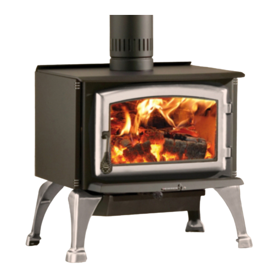
Solution 1.8
(EB00002 model)
Safety tested according to ULC S627
and UL 1482 Standards by
Intertek Testing Services
READ AND KEEP THIS MANUAL FOR REFERENCE
This manual is available for free download on the manufacturer's web site. It is a
copyrighted document. Re-sale is strictly prohibited. The manufacturer may update this
manual from time to time and cannot be responsible for problems, injuries, or damages
arising out of the use of information contained in any manual obtained from unauthorized
sources.
Printed in Canada
INSTALLATION
AND OPERATION
MANUAL
US ENVIRONMENTAL PROTECTION
AGENCY PHASE II CERTIFIED WOOD
STOVE
www.enerzone-intl.com
Stove Builder International Inc.
250, rue de Copenhague,
St-Augustin-de-Desmaures
(Quebec) Canada G3A 2H3
Tel: (418) 878-3040
Fax: (418) 878-3001
45189A
17-10-2014
Advertisement
Table of Contents

Related Manuals for Enerzone EB00002


Summary of Contents for Enerzone EB00002
- Page 1 INSTALLATION AND OPERATION MANUAL US ENVIRONMENTAL PROTECTION Solution 1.8 AGENCY PHASE II CERTIFIED WOOD STOVE (EB00002 model) Safety tested according to ULC S627 www.enerzone-intl.com and UL 1482 Standards by Intertek Testing Services Stove Builder International Inc. 250, rue de Copenhague,...
- Page 2 THANK YOU FOR CHOOSING THIS ENERZONE WOOD STOVE As one of North America’s largest and most respected wood stove and fireplace manufacturers, Stove Builder International takes pride in the quality and performance of all its products. We want to help you get maximum satisfaction as you use this product.
-
Page 3: Table Of Contents
Table of content PART A - OPERATION AND MAINTENANCE ....... 6 Safety Information ..............6 1.1 Summary of Operation and Maintenance Cautions and Warnings ........6 General Information ..............7 2.1 Solution 1.8 Specifications ....................7 2.2 ... - Page 4 Maintaining Your Wood Heating System ....... 20 5.1 Stove Maintenance ......................20 5.1.1 Plated Finish Maintenance .................... 20 5.1.2 Cleaning Door Glass ..................... 20 5.1.3 Replacing the Door Gasket ................... 22 5.1.4 Replacing the Glass Gasket and/or the Glass .............. 22 5.1.5 ...
- Page 5 Fan, and Thermodisc (AC01000/AC02055) ......... 48 Appendix 7: Installation of Secondary Air Tubes and Baffle ... 50 Appendix 8: Exploded Diagram and Parts List ......53 ENERZONE LIMITED LIFETIME WARRANTY ......56 Solution 1.8 Installation and Operation Manual...
-
Page 6: Part A - Operation And Maintenance
PART A - OPERATION AND MAINTENANCE Please see Part B for installation instructions. 1 Safety Information 1.1 Summary of Operation and Maintenance Cautions and Warnings • HOT WHILE IN OPERATION, KEEP CHILDREN, CLOTHING AND FURNITURE AWAY. CONTACT MAY CAUSE SKIN BURNS. GLOVES MAY BE NEEDED FOR STOVE OPERATION. -
Page 7: General Information
General Information 2.1 Solution 1.8 Specifications Fuel Type Cordwood Test Standards (safety) ULC S627 and UL 1482 Test Standard (emissions) EPA Method 28 (40 CFR Part 60) Heating capacity range* 500 to 1800 sq. ft. (46 to 167 m Maximum heat output** 34,000 BTU/h (10 kW/h) (EPA test fuel) Maximum heat output**... - Page 8 Solution 1.8 Installation and Operation Manual...
-
Page 9: Zone Heating And How To Make It Work For You
2.2 Zone Heating and How to Make it Work for You Your new Solution 1.8 wood stove is a space heater, which means it is intended to heat the area it is installed in, as well as spaces that connect to that area, although to a lower temperature. This is called zone heating and it is an increasingly popular way to heat homes or spaces within homes. -
Page 10: The Benefits Of Low Emissions And High Efficiency
2.3 The Benefits of Low Emissions and High Efficiency The low smoke emissions produced by the special features inside the Solution 1.8 firebox mean that your household will release up to 90 percent less smoke into the outside environment than if you used an older conventional stove. -
Page 11: Fuel
3 Fuel 3.1 Materials That Should Not be Burned • GARBAGE OF ANY KIND, • COAL OR CHARCOAL, • TREATED, PAINTED OR COATED WOOD, • PLYWOOD OR PARTICLE BOARD, • FINE PAPER, COLORED PAPER OR CARDBOARD, • SALT WATER DRIFTWOOD •... -
Page 12: Log Length
3.2.3 Log Length Logs should be cut about 1” (25 mm) shorter than the firebox so they fit in easily. Pieces that are even slightly too long make loading the stove very difficult. The most common standard length of firewood is 16” (400 mm). The pieces should be a consistent length, with a maximum of 1”... -
Page 13: How To Dry Firewood
3.2.5 How to Dry Firewood Firewood that is not dry enough to burn is the cause of most complaints about wood inserts. Continually burning green or unseasoned wood produces more creosote and involves lack of heat and dirty glass door. See Section 5: Maintaining your wood heating system for concerns about creosote. -
Page 14: Manufactured Logs
You could buy a wood moisture meter to test your firewood. 3.3 Manufactured Logs Do not burn manufactured logs made of wax impregnated sawdust or logs with any chemical additives. Manufactured logs made of 100% compressed sawdust can be burned, but be careful burning too much of these logs at the same time. -
Page 15: Lighting Fires
Burn one or two small fires to begin the curing and conditioning process. Then build bigger and hotter fires until there is no longer any paint smell from the stove. Once the paint smell disappears, your stove is ready for serious heating. 4.2 Lighting Fires Each person who heats with wood develops their own favorite way to light fires. -
Page 16: Two Parallel Logs
Start by placing three or four full-sized split pieces of dry firewood in the firebox. Next, place 4 or 5 more finely split pieces of firewood (2” to 3” [50 mm to 75 mm] in dia.) on the base logs at right angles (log cabin style). -
Page 17: Ash Removal
wood should provide several hours of heating. The size of each load can be matched to the amount of heat needed. When you burn in cycles, you rarely need to open the stove’s loading door while the wood is flaming. This is an advantage because there is more chance that smoke will leak from the stove when the door is opened as a full fire is burning. -
Page 18: Firing Each New Load Hot
4.3.4 Firing Each New Load Hot Place the new load of wood on and behind the charcoal, and not too close to the glass. Close the door and open the air control fully. Leave the air control fully open until the firebox is full of flames, the wood has charred to black and its edges are glowing red. -
Page 19: Building Different Fires For Different Needs
4.3.6 Building Different Fires for Different Needs Using the air control is not the only way to match the stove’s heat output to the heat demand. Your house will need far less heat in October than in January to be kept at a comfortable temperature. If you fill the firebox full in fall weather, you will either overheat the space or turn the stove down so much that the fire will be smoky and inefficient. -
Page 20: Maintaining Your Wood Heating System
The table below provides a very general indication of the maximum burn cycle times you are likely to experience, based on firebox volume. MAXIMUM FIREBOX VOLUME BURN TIME <1.5 cubic feet 3 to 5 hours 1.5 c.f. to 2.0 c.f 5 to 6 hours 2.0 c.f. - Page 21 when the stove is cool by wiping with a damp cloth or paper towel and then drying. Never try to clean the glass when the stove is hot. In spring and fall when the stove is run at lower temperatures, you may see some light brown stains forming, especially at the lower corners of the glass.
-
Page 22: Replacing The Door Gasket
5.1.3 Replacing the Door Gasket It is important to maintain the gasket in good condition. After a year or more of use, the door gasket will compress and become hard, which may allow air to leak past it. You can test the condition of the door gasket by closing and latching the door on a strip of paper. -
Page 23: Cleaning And Painting The Stove
Do not abuse the glass door by striking or slamming shut. Do not use the stove if the glass is broken. To change the glass, perform the same operation described above. 5.1.5 Cleaning and Painting the Stove Do not attempt to clean or paint the stove when the unit is hot. Painted surfaces can be wiped down with a damp cloth. -
Page 24: Cleaning The Chimney
Contact your local municipal or provincial fire authority for information on how to handle a chimney fire. Have a clearly understood plan to handle a chimney fire. 5.2.3 Cleaning the Chimney Chimney cleaning can be a difficult and dangerous job. don’t have experience cleaning chimneys, you might... -
Page 25: Part B - Installation
PART B - INSTALLATION 6 Safety Information 6.1 Summary of Installation Cautions and Warnings • THE INFORMATION GIVEN ON THE CERTIFICATION LABEL AFFIXED TO THE APPLIANCE ALWAYS OVERRIDES THE INFORMATION PUBLISHED, IN ANY OTHER MEDIA (OWNER’S MANUAL, CATALOGUES, FLYERS, MAGAZINES AND/OR WEB SITES). -
Page 26: Regulations Covering Stove Installation
6.2 Regulations Covering Stove Installation When installed and operated as described in these instructions, the Solution 1.8 wood stove is suitable for use as a freestanding heater in residential installations. The Solution 1.8 wood stove may not be installed in a sleeping room of a mobile home. In Canada, the CSA B365 Installation Code for Solid Fuel Burning Appliances and Equipment and the CSA C22.1 Canadian National Electrical Code are to be followed in the absence of local code requirements. - Page 27 CLEARANCES CLEARANCES (SINGLE WALL PIPE) (DOUBLE WALL PIPE) CANADA CANADA 14’’ (356 mm) 14’’ (356 mm) 6’’ (152 mm) 6’’ (152 mm) 12’’ (305 mm) 12’’ (305 mm) 11’’ (279 mm) 11’’ (279 mm) 7’’ (178 mm) 7’’ (178 mm) 5’’...
- Page 28 Clearances to combustible materials and floor protection Solution 1.8 Installation and Operation Manual...
-
Page 29: Floor Protector
7.3 Floor protector Your stove has been conceived to prevent the floor from overheating. However, it must be placed on a noncombustible surface to protect the floor from hot embers that could fall from the stove while loading or cleaning. There are differences between floor protections in Canada and in the United States, as it is illustrated in the table below and on the figure Clearances to combustible materials and floor protection. -
Page 30: Reducing Wall And Ceiling Clearances Safely
7.4 Reducing Wall and Ceiling Clearances Safely It is often desirable to reduce the minimum installation clearances by placing the stove closer to walls so the installation takes up less floor space. You can safely reduce the minimum clearances permanently installing shield between the stove and combustible... - Page 31 Clearances for shield construction Solution 1.8 Installation and Operation Manual...
-
Page 32: Table Of Clearance Reduction Percentages
7.4.2 Table of Clearance Reduction Percentages Clearances may be reduced by these percentages Sides Top % Type of shield and rear % (ceiling) Can/USA Can/USA min. min. Sheet metal, a minimum of 24 gauge (0.61 mm) in thickness , spaced out at least 25 mm (1 in)*... -
Page 33: The Venting System
8 The Venting System 8.1 General The venting system, made up of the chimney and the connecting pipe between the stove and the chimney, acts as the engine that drives your wood heating system. Even the best stove will not function safely and efficiently as intended if it is not connected to a suitable chimney. -
Page 34: Factory-Built Metal Chimneys In Mobile Homes
8.2.2 Factory-built Metal Chimneys in mobile homes For use in a mobile home, this stove is to be connected to a 6” in diameter double wall factory built chimney conforming to CAN/ULC-S629, Standards 650°C Factory-built chimney. The total length of the flue system should be at least (15) feet including elbows, from the top of the stove. -
Page 35: Masonry Chimneys
8.2.3 Masonry Chimneys The stove may also be connected to a masonry chimney, provided the chimney complies with the construction rules found in the building code enforced locally. The chimney must have either a clay liner or a suitably listed stainless steel liner. -
Page 36: Why Inside Chimneys Are Preferred
8.4.1 Why inside chimneys are preferred Venting systems that rise straight up from the stove flue collar provide the best performance. Chimneys that rise inside the warm space of the house tend to provide a small amount of draft even when there is no fire burning. This means that when you light a fire, the initial smoke goes up the chimney and strong draft builds quickly as the chimney flue warms up. -
Page 37: Supply Of Combustion Air
There are two reasons why the chimney in the house at right will cold backdraft when it is cold outside and there is no fire burning in the stove. First, the chimney runs up the outside of the house, so the air in it is colder and denser than the warm air in the house. -
Page 38: Installing The Chimney Connector
Some jurisdictions in the United States require that wood stoves have a supply of combustion air from outdoors. If you do install an air supply through the wall of the house, be aware that its pressure can be affected during windy weather. If you notice changes in wood stove performance in windy weather, and in particular if smoke puffs from the stove, you should disconnect the outdoor air duct from the stove and remove the duct. -
Page 39: Installation Of Single Wall Chimney Connector
8.6.1 Installation of Single Wall Chimney Connector The chimney connector assembly has been called ‘the weak link’ in the safety of wood heating systems because failure to install the connector properly (which has been common in the past) can result in house fires. The best flue pipe assembly is one that rises straight up from the stove to the base of the chimney with no elbows. - Page 40 The rules below are based on those found in the CSA B365 installation code. Please carefully follow these installation instruction rules, or those enforced where you live. • Maximum overall length of straight pipe: 3 m (10 ft.) including elbows. •...
-
Page 41: Appendix 1: Installing The Legs Or Pedestal
Appendix 1: Installing the Legs or Pedestal The leg or pedestal kit must be assembled to the firebox before positioning the stove. See installation instructions below: 1- Remove the firebricks, the ash dump plug and the loading door from the stove to avoid breaking any parts and facilitate handling in the followings steps. - Page 42 Leg kit installation: 4- Secure each leg (A) on support (B) using (2) washers (C) and (2) nuts (D) supplied in the kit. Repeat the same mounting procedure for the second support. 5- Secure both leg support assembly to the underside of the firebox using the bolts, washers and nuts removed in step 3.
- Page 43 Pedestal kit installation: Follow step 1, 2 and 3 of the leg kit installation. 5- Secure pedestal base to the underside of the firebox using the bolts, washers and nuts removed in step 3. Note: Insert each bolt from the inside of the firebox, this will allow the bricks to sit more evenly on the floor of the firebox.
-
Page 44: Appendix 2: Installing The Door Overlay Sold As An Option
Appendix 2: Installing the Door Overlay Sold as an Option In order to complete the assembly of your wood stove, you need to install the door overlay. See figure below for installation instructions: Position the overlay (A) on the door frame and secure it from the inside of the door using the 4 included screws (B). -
Page 45: Appendix 3: Installing Trims
Appendix 3: Installing Trims Your freestanding SOLUTION 1.8 wood stove is equipped with decorative u-shaped trims. See installation instructions below: 1- Remove the 7 screws that secure the side panels and the rear top air deflector. 2- Slide the panels towards the front to release them from the front brackets. -
Page 46: Appendix 4: Installing The Optional Air Mate (Ac01230)
Appendix 4: Installing the Optional Air Mate (AC01230) Most freestanding Enerzone wood stoves can be equipped with an optional air mate. This device accumulates heat and increases the air flow. See below for installation instructions: 1- Remove the 3 screws holding the rear heat shield deflector. -
Page 47: Appendix 5: Installing The Optional Fresh Air Kit
Appendix Installing Optional Fresh (OA10500/AC02090) When installed with a fresh air kit, the stove must be anchored to the floor This mobile home approved stove requires installation of a fresh air kit (A) and an insulated fresh air intake pipe (B), sold separately. Installation on the back Installation on the bottom Solution 1.8 Installation and Operation Manual... -
Page 48: Appendix 6: Installation And Use Of Optional Air Circulation Fan, And Thermodisc (Ac01000/Ac02055)
You can purchase this option through your ENERZONE dealer. Make sure to specify this part number: # AC01000 The fan has a rheostat, see the illustration on the right to identify the different adjustment positions;... - Page 49 CAUTION: ENSURE THAT THE FAN’S POWER CORD IS NOT IN CONTACT WITH ANY SURFACE OF THE STOVE TO PREVENT ELECTRICAL SHOCK OR FIRE DAMAGE. DO NOT RUN THE POWER CORD BENEATH THE STOVE. Solution 1.8 Installation and Operation Manual...
-
Page 50: Appendix 7: Installation Of Secondary Air Tubes And Baffle
Appendix 7: Installation of Secondary Air Tubes and Baffle 1- Remove the hatched bricks as per drawing. 2- Starting with the rear tube, lean and insert the right end of the secondary air tube into the rear right channel hole. Then lift and insert the left end of the tube into the rear left channel. - Page 51 4- Lock it in place by using a cotter pin on the right side. 5- Repeat step 2 and 3 for the other secondary air tubes. To remove the tubes use the above steps in reverse order. Installation order: A: tubes and cotter pins B: C-cast baffle board C: insulation blanket D: insulation blanket weight...
- Page 52 Note that secondary air tubes (A) can be replaced without removing the baffle board (B). Important Notes: The air tubes are identified for placement as follows: Model Type of tube Front ► 40 holes of 0.156" Solution 1.8 Middle rear ► 80 holes of 0.109’’ Rear ►...
-
Page 53: Appendix 8: Exploded Diagram And Parts List
Appendix 8: Exploded Diagram and Parts List Solution 1.8 Installation and Operation Manual... - Page 54 IMPORTANT: THIS IS DATED INFORMATION. When requesting service or replacement parts for your stove, please provide the model number and the serial number. We reserve the right to change parts due to technology upgrade or availability. Contact an authorized dealer to obtain any of these parts.
- Page 55 Item Description 31 24012 CAST IRON LEG WITH LEVELING BOLT 31 PL24012PN ENERZONE NICKEL PLATED CAST IRON LEG WITH LEVELING BOLT 31 PL24012PG ENERZONE GOLD PLATED CAST IRON LEG WITH LEVELING BOLT 32 30050 LEVELING BOLT 3/8-16 X 1 1/2"...
-
Page 56: Enerzone Limited Lifetime Warranty
Paint (peeling), gaskets, insulation, firebrick, and ceramic fibre 1 year blankets. *Pictures required Shall your unit or a components be defective, contact immediately your ENERZONE dealer. Prior to your call make sure you have the following information necessary to your warranty claim treatment: ...
Need help?
Do you have a question about the EB00002 and is the answer not in the manual?
Questions and answers