Table of Contents
Advertisement
Quick Links
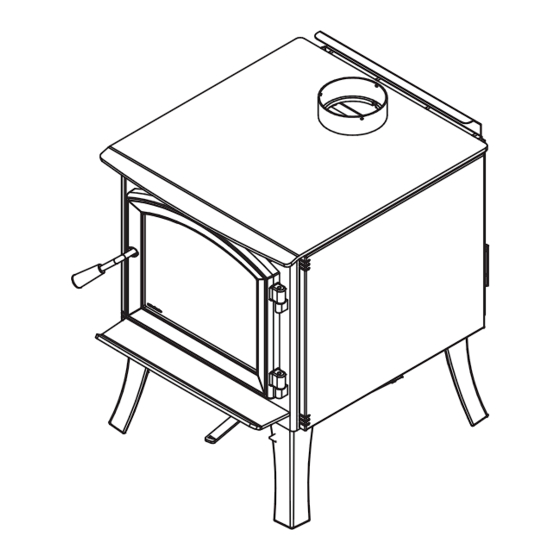
Installation and Operation Manual
SOLUTION 3.3
(EB00060 model)
US Environmental Protection Agency
phase II certified wood stove compliant
with 2020 cord wood standard
Safety tested according to ULC S627,
UL 1482 and UL 737 standards by an
accredited laboratory.
MOBILE
HOME
CONTACT LOCAL BUILDING OR FIRE OFFICIALS ABOUT RESTRICTIONS AND INSTALLATION INSPECTION REQUIREMENTS IN
LOCAL AREA.
READ THIS ENTIRE MANUAL BEFORE INSTALLATION AND USE OF THIS WOOD STOVE. FAILURE TO FOLLOW THESE
INSTRUCTIONS COULD RESULT IN PROPERTY DAMAGE, BODILY INJURY OR EVEN DEATH.
READ AND KEEP THIS MANUAL FOR REFERENCE
Printed in Canada
46137A
2020-06-20
Advertisement
Table of Contents

Related Manuals for Enerzone EB00060


Summary of Contents for Enerzone EB00060
- Page 1 Installation and Operation Manual SOLUTION 3.3 (EB00060 model) US Environmental Protection Agency phase II certified wood stove compliant with 2020 cord wood standard Safety tested according to ULC S627, UL 1482 and UL 737 standards by an accredited laboratory. MOBILE...
- Page 3 It is also highly recommended to register the warranty online at https://www.enerzone-intl.com/en/warranty/warranty-registration/ Registering the warranty will help to quickly find the information needed on the unit.
-
Page 4: Table Of Contents
TABLE OF CONTENTS PART A - OPERATION AND MAINTENANCE ................7 1. Safety Information ........................7 2. General Information ........................ 8 2.1 Performances ........................8 2.2 Specifications ........................9 2.3 Dimensions ........................10 2.4 Materials ...........................11 2.5 Zone Heating ........................11 2.6 Emissions and Efficiency ....................12 3. - Page 5 Appendix 7: Optional Blower and Thermodisc Installation ............. 53 Appendix 8: Air Tubes and Baffle Installation ................54 Appendix 9: Mobile Home Installation ..................56 Appendix 9: Exploded Diagram and Parts List ................ 57 ENERZONE Limited Lifetime Warranty ..................62 Dealer: Installer: Phone Number: Serial Number: Installation and Operation Manual - Solution 3.3...
- Page 6 CERTIFICATION PLATE Page 6 Installation and Operation Manual - Solution 3.3...
-
Page 7: Part A - Operation And Maintenance
PART A - OPERATION AND MAINTENANCE 1. Safety Information • This stove has been tested for use with an open door in conjunction with a fire screen, sold separately. The door may be opened, or fire screen removed only during lighting procedures or reloading. -
Page 8: General Information
2. General Information Performances Values are as measured per test method, except for the recommended heating area, firebox volume, maximum burn time and maximum heat output. Model Solution 3.3 (EB00060) Combustion Technology Non-catalytic Fuel Type Dry Cordwood Recommended heating area (sq. ft. -
Page 9: Specifications
Specifications Maximum log length 20 in (508 mm) east-west Flue outlet diameter 6 in (150 mm) Recommended connector pipe diameter 6 in (150 mm) Type of chimney ULC S629, UL 103 HT (2100 °F) Baffle material C-Cast Approved for alcove installation Approved for mobile home installation Type of door Simple, glass with cast iron frame... -
Page 10: Dimensions
Dimensions 23 5/8" 600mm 24 1/4" 30 7/8" 616mm 12 1/8" 783mm 30 3/4" 308mm 782mm 27 5/8" 702mm 25 1/8" 638mm 18 1/2" 471mm 6 5/8" 168mm 11 3/4" 297mm 14 5/8" 370mm 6" Ø 153mm 25 1/2" 648mm 23 7/8"... -
Page 11: Materials
Materials The body of this stove, which is most of its weight, is carbon steel. Should it ever become necessary many years in the future, almost the entire stove can be recycled into new products, thus eliminating the need to mine new materials. The paint coating on the stove is very thin. -
Page 12: Emissions And Efficiency
The success of zone heating will depend on several factors, including the correct sizing and location of the stove, the size, layout and age of the home and the climate zone. Three-season vacation homes can usually be heated with smaller stoves than houses that are heated all winter. Emissions and Efficiency The low smoke emissions produced by the special features inside this stove firebox mean that the household will release up to 90% less smoke into the outside environment than if an older... -
Page 13: Log Length
Softer woods make good fuel for mild weather in spring and fall because they light quickly and produce less heat. Softwoods are not as dense as hardwoods so a given volume of wood contains less energy. Using softwoods avoids overheating the house, which can be a common problem with wood heating in moderate weather. -
Page 14: Drying Time
Drying Time Firewood that is not dry enough to burn is the cause of most complaints about wood burning appliances. Continually burning green or unseasoned wood produces more creosote and involves lack of heat and dirty glass door. Firewood with a moisture content between 15% and 20% will allow the stove to produce its highest possible efficiency. -
Page 15: Operating The Stove
4. Operating the Stove This wood heater has a manufacturer-set minimum low burn rate that must not be altered. It is against federal regulations to alter this setting or otherwise operate this wood heater in a manner inconsistent with operating instructions in this manual. -
Page 16: Burning Wood Efficiently
The blower has a variable speed control that can be adjusted in three different positions; either from high (HI) to low (LO) or closed (OFF). Allow the stove to reach operating temperature (approximately one hour) before turning on the blower, since increased airflow from the blower will remove heat and affect the start up combustion efficiency. -
Page 17: Combustion Cycles
Then add two or three small pieces of firewood. Open the air intake control completely and ignite the newspaper. Leave the door slightly ajar. Once the fire has ignited, the door can be closed with the air control still fully open. When the kindling is almost completely burned, standard firewood pieces can be added. -
Page 18: Rekindling A Fire
Trying to produce a steady heat output by placing a single log on the fire at regular intervals is not recommended. Always place at least three, and preferably more pieces on the fire at a time so that the heat radiated from one piece helps to ignite the pieces next to it. Each load of wood should provide several hours of heating. -
Page 19: Air Intake Control
Ashes almost always contain live embers that can stay hot for days and which release carbon monoxide gas. Ashes should be placed in a tightly covered metal container. The container must be placed on a non-combustible floor or on the ground well away from all combustible materials. If the ashes are disposed of by burial in soil or otherwise locally dispersed, they should be kept in a closed metal container until they are completely cooled. - Page 20 5.7.2 Long Lasting Fire For a fire that will last up to eight hours but will not produce intense heat, use soft wood and place the logs compactly in the firebox. Before reducing the air intake, the load will have to burn at full heat for long enough for charring the surface of the logs.
-
Page 21: Maintenance
North-south loads allow more wood to be loaded at the same time. On the other hand, they break into smaller pieces faster. North-south loading is good for high output, long lasting fires for cold weather. East-west loads allow a limited amount of wood since too many logs could cause them to fall on the glass. - Page 22 When the stove runs at a low combustion rate, light brown stains may form, especially in the lower corners of the glass. This indicates that the fire has been smoky and some of the smoke has condensed on the glass. It also indicates incomplete combustion of the wood, which also means more smoke emissions and faster formation of creosote in the chimney.
-
Page 23: Door
6.3.3 Gasket The glass gasket is flat, adhesive-backed, woven fibreglass. The gasket must be centred on the edge of the glass. Follow the steps of the previous section to remove the glass. Remove the old gasket and clean the glass thoroughly. Peel back a section of the paper covering the adhesive and place the gasket on a table with the adhesive side up. - Page 24 6.4.2 Gasket It is important to replace the gasket with another having the same diameter and density to maintain a good seal. Remove the door and place it face-down on something soft like a cushion of rags or a piece of carpet. Remove the old gasket from the door.
-
Page 25: Exhaust System
all door hinge pressure screws when they are at the desired positions. Configurations 1-2-3-4-5-6, show in which direction these act on the adjustment of the door Exhaust System Wood smoke can condense inside the chimney, forming a inflammable deposit called creosote. If creosote builds up in the system, it can ignite when a hot fire is burned in the stove. - Page 26 Be aware that the hotter the fire the less creosote is deposited, and weekly cleaning may be necessary in mild weather even though monthly cleaning may be enough in the coldest months. Contact your local municipal or provincial fire authority for information on how to handle a chimney fire.
-
Page 27: Part B - Installation
PART B - INSTALLATION 7. Safety Information and Standards • The information given on the certification label affixed to the appliance always overrides the information published, in any other media (owner’s manual, catalogues, flyers, magazines and web sites). • Mixing of appliance components from different sources or modifying components may result in hazardous conditions. -
Page 28: Location Of The Certification Label
Location of the Certification Label Since the information given on the certification label affixed to the appliance always overrides the information published, in any other media (owner’s manual, catalogues, flyers, magazines and web sites) it is important to refer to it in order to have a safe and compliant installation. In addition, important information about the stove can be found (model, serial number, etc.). - Page 29 48" 36" 122 cm 92 cm Clearances - Top Clearances - Corner 84" (L) 213 cm Clearances - Side Installation and Operation Manual - Solution 3.3 Page 29...
-
Page 30: Clearances
Clearances APPLIANCE CLEARANCES WITH SINGLE APPLIANCE CLEARANCES WITH DOUBLE WALL PIPE CONNECTOR WALL PIPE CONNECTOR Canada Canada 14 ½" (368 mm) 14 ½" (368 mm) 7 ½" (191 mm) 7 ½" (191 mm) 12" (305 mm) 12" (305 mm) 12" (305 mm) 12"... - Page 31 8.1.2 With Airmate APPLIANCE CLEARANCES WITH DOUBLE DISTANCES13 FROM DOUBLE WALL PIPE WALL PIPE CONNECTOR CONNECTOR Canada Canada 6" (152mm) 6" (152mm) 9 ½" (241 mm) 9 ½" (241 mm) 12" (305 mm) 12" (305 mm) 20 ¾" (527 mm) 20 ¾"...
- Page 32 8.1.3 With Heat Shield AC02762 and Lowered Ceiling APPLIANCE CLEARANCES WITH DOUBLE DISTANCES FROM PIPE CONNECTOR WALL PIPE CONNECTOR WITH DOUBLE WALL PIPE CONNECTOR Canada Canada 5" (127 mm) 5" (127 mm) 8 ½" (216 mm) 8 ½" (216 mm) 3"...
- Page 33 8.1.6 Mobile Home with Airmate It is strictly forbidden to install a unit with a single wall pipe in a mobile home. APPLIANCE CLEARANCES WITH DOUBLE DISTANCES FROM PIPE CONNECTOR WALL PIPE CONNECTOR WITH DOUBLE WALL PIPE CONNECTOR Canada Canada 6"...
-
Page 34: Floor Protection
Floor Protection This stove is designed to prevent the floor from overheating. However, it must be placed on a nonflammable surface to protect the floor from hot embers that may fall during loading. The floor protection must be a continuous, non combustible material, such as steel with a minimum thickness of 0.015"... - Page 35 CLEARANCES MAY BE REDUCED BY THESE PERCENTAGES TYPE OF SHIELD SIDES AND REAR TOP (CEILING) CAN / CAN / USA (%) MIN. USA (%) MIN. Sheet metal, a minimum of 24 gauge (0.61 mm) in thickness , spaced out at least 1" (25 mm)* by non-combustible spacers 12"...
- Page 36 8.3.1 Shield Construction Rules − Adhesives used in shield construction must not ignite or lose its adhesive qualities at temperatures likely to be encountered. − Mounting hardware which extends from the shield surface into combustibles may be used only at the edges of the shield.
- Page 37 Heat shield clearances Heat shield clearances Heat shield clearances Installation and Operation Manual - Solution 3.3 Page 37...
-
Page 38: The Venting System
9. The Venting System General The venting system, made of the chimney and the connecting pipe between the stove and the chimney, acts as the engine that drives the wood heating system. Even the best stove will not function safely and efficiently if it is not connected to a suitable chimney. The heat in the flue gases that pass from the stove and chimney connector into the chimney is not waste heat. - Page 39 9.2.2 Factory-Built Metal Chimneys in Mobile Homes For use in a mobile home, this stove is to be connected to a 6" double wall factory built chimney pipe conforming to ULC-S629 or UL 103HT standards for 650°C Factory-built chimney. The total length of the flue system should be at least 12 feet including elbows, from the top of the stove.
-
Page 40: Minimum Chimney Height
Minimum Chimney Height The top of the chimney should be tall enough to be above the air turbulence caused when wind blows against the house and its roof. The chimney must extend at least 3 ft. (1 m) above the highest point of contact with the roof, and at least 2 ft. -
Page 41: Supply Of Combustion Air
If there is no fire burning in a heater connected to a chimney that is shorter than the warm space inside the house, the slight negative pressure in the lower part of the house will compete against the desired upward flow in the chimney. This occurs for the two following reasons: First, the chimney runs up the outside of the house, so the air in it is colder and denser than the warm air in the house. -
Page 42: Installing The Chimney Connector
If an air intake is installed through the wall of the house, its pressure can vary during windy weather. If there are changes in wood stove performance in windy weather, and in particular if smoke puffs from the stove, the air duct should be disconnected from the stove to determine if it is the cause of the problem. - Page 43 • Maximum overall length of horizontal pipe: 10 ft. (3 m) including elbows. • Minimum clearance from combustible material: 18" (450 mm). The minimum clearance may be reduced by 50 percent to 9" (225 mm) if suitable shielding is installed either on the pipe or on the combustible surface.
-
Page 44: Appendix 1: Legs Installation
APPENDIx 1: LEGS INSTALLATION Remove the door, the firebricks, and the ash plug from the stove, if desired. Put the stove on its back. Remove and dispose of the two freight supports (D). Keep the nuts (C) and washers (B) for step 4. Page 44 Installation and Operation Manual - Solution 3.3... - Page 45 Install the legs (E) on the legs supports (F). Secure with the washers (G) and nuts (H) supplied with the leg assembly. With the nuts (C) and washers (B) removed in step 2, secure both leg assemblies to the stove. Installation and Operation Manual - Solution 3.3 Page 45...
- Page 46 Install the air control cover (J) with screws (K) and nuts (L). Put the stove on its legs, install the ash drawer included with the kit. Put back the firebricks, the ash plug and the door on the stove (See step 1). The baffle and the bricks must be put back in the right place after the final positioning of the stove.
-
Page 47: Appendix 2: Pedestal Installation
APPENDIx 2: PEDESTAL INSTALLATION Remove the door, the firebricks and the ash plug from the stove, if desired. Install the pedestal (D) on the stove and screw it in place using washers (B) and nuts (C). Installation and Operation Manual - Solution 3.3 Page 47... - Page 48 Put the stove on its pedestal and install the fresh air panel (F) with the screws (G), the air control cover (H) with the screws (J) and install the ash drawer (K). Put back the bricks, the spacers, the ash plug and the door on the stove. See step 1. The baffle and the bricks must be put back in the right place after the final positioning of the stove.
-
Page 49: Appendix 3: Decorative Panels
APPENDIx 3: DECORATIVE PANELS To remove the decorative panel (C), remove the screws (B) and push forward on the panel to unhook it from the bracket (E). Installation and Operation Manual - Solution 3.3 Page 49... -
Page 50: Appendix 4: Optional Airmate Installation
APPENDIx 4: OPTIONAL AIRMATE INSTALLATION Install the deflector (A) with the screws (B). Install the airmate (C) with the screws kept from the previous step (B). Page 50 Installation and Operation Manual - Solution 3.3... -
Page 51: Appendix 5: Fresh Air Intake Kit Installation
APPENDIx 5: OPTIONAL FRESH AIR INTAKE KIT INSTALLATION This mobile home approved stove requires the installation of a fresh air intake kit (A) and an insulated fresh air intake pipe (HVAC type, must meet ULC S110 or UL 181 class 0 or class 1) (B), sold separately. -
Page 52: Appendix 6: Optional Fire Screen Installation
APPENDIx 6: OPTIONAL FIRE SCREEN INSTALLATION Warning: This product should not be operated with door open using fire screen (AC01397) in the United States or provinces where any particulate matter emission rate limit is enforced (ex: US EPA). Open the door. Hold the fire screen by the two handles and bring it close to the door opening. -
Page 53: Appendix 7: Optional Blower And Thermodisc Installation
APPENDIx 7: OPTIONAL BLOWER AND THERMODISC INSTALLATION A blower and a thermodisc, sold separately, can be installed on the stove. The installation of the blower is identical for a stove on legs or pedestal. Thermodisc allows the blower to operate only when the stove is hot enough. -
Page 54: Appendix 8: Air Tubes And Baffle Installation
APPENDIx 8: AIR TUBES AND BAFFLE INSTALLATIO Starting with the rear tube, lean and insert the right end of the secondary air tube into the rear right channel hole. Then lift and insert the left end of the tube into the rear left channel. Align the notch in the left end of the tube with the key of the left air channel hole. - Page 55 Note that secondary air tubes (B) can be replaced without removing the baffle board (A) and that all tubes are identical.. Installation and Operation Manual - Solution 3.3 Page 55...
-
Page 56: Appendix 9: Mobile Home Installation
APPENDIx 9: MOBILE HOME INSTALLATION For a stove on legs, install a plate (L) on each leg and screw it in place with the proper hardware (M). For a stove on a pedestal, remove the plugs (N) and screw the base on the floor with the proper hardware (O). -
Page 57: Appendix 9: Exploded Diagram And Parts List
APPENDIx 10: ExPLODED DIAGRAM AND PARTS LIST DETAIL B DETAIL C Installation and Operation Manual - Solution 3.3 Page 57... - Page 58 IMPORTANT: THIS IS DATED INFORMATION. When requesting service or replacement parts for your unit, please provide the model number and the serial number. We reserve the right to change parts due to technology upgrades or availability. Contact an authorized dealer to obtain any of these parts.
- Page 59 Item Description 44028 CERAMIC THERMODISC F110-20F 60013 POWER CORD 96" X 18-3 type SJT (50 pcs per carton) AC05959 METALLIC BLACK STOVE PAINT - 342 g (12oz) AEROSOL SE46137 SOLUTION 3.3 MANUAL KIT AC01204 5"Ø FRESH AIR INTAKE KIT FOR WOOD STOVE ON LEGS AC01336 5"Ø...
-
Page 62: Enerzone Limited Lifetime Warranty
Shall your unit or a component be defective, contact immediately your ENERZONE dealer. To accelerate processing of your warranty claim, make sure to have on hand the following information when calling: •... - Page 64 Resale is strictly prohibited. The manufacturer may update St-Augustin-de-Desmaures (Québec) Canada this document from time to time and cannot be responsible G3A 2H3 for problems, injuries, or damages arising out of the use 418-908-8002 of information contained in any document obtained from https://www.enerzone-intl.com unauthorized sources. tech@sbi-international.com...
Need help?
Do you have a question about the EB00060 and is the answer not in the manual?
Questions and answers