Table of Contents
Advertisement
Quick Links
INSTALLATION
AND OPERATION
MANUAL
Solution 3.4
(Model EB00032)
Distributed by:
My Fireplace Australia Pty Limited
Factory 2, 5-7 Hogan Court, Pakenham,
Victoria 3810
Phone number 03 59 415 008
www.myfireplaceaustralia.com.au
READ AND KEEP THIS MANUAL FOR REFERENCE
This manual is available for free download on the distributor's web site. It is a copyrighted
document. Re-sale is strictly prohibited. The distributor may update this manual from time to time
and cannot be responsible for problems, injuries, or damages arising out of the use of information
contained in any manual obtained from unauthorized sources.
45732A
Printed in Canada
09-09-2015
Advertisement
Table of Contents

Subscribe to Our Youtube Channel
Related Manuals for Enerzone EB00032


Summary of Contents for Enerzone EB00032
- Page 1 INSTALLATION AND OPERATION MANUAL Solution 3.4 (Model EB00032) Distributed by: My Fireplace Australia Pty Limited Factory 2, 5-7 Hogan Court, Pakenham, Victoria 3810 Phone number 03 59 415 008 www.myfireplaceaustralia.com.au READ AND KEEP THIS MANUAL FOR REFERENCE This manual is available for free download on the distributor’s web site. It is a copyrighted document.
- Page 2 THANK YOU FOR CHOOSING THIS WOOD FIRE We want to congratulate you on your purchase and wish to help you get maximum satisfaction from your wood fire. In the pages that follow, we will give you advice on wood heating and controlled combustion as well as technical specifications regarding installation, operation and maintenance of the model you have chosen.
-
Page 3: Table Of Contents
Zone Heating and How to Make it Work for You ..............10 The Benefits of Low Emissions and High Efficiency ............. 10 Enerzone’s Commitment to You and the Environment ............11 2.4.1 What is Your New Wood fire Made Of? ................11 Fuel .................... - Page 4 Maintaining Your Wood Heating System ........23 Wood fire Maintenance ...................... 23 5.1.1 Plated Finish Maintenance ....................23 5.1.2 Cleaning Door Glass ......................23 5.1.3 Door Adjustment ......................24 5.1.4 Replacing the Door Gasket....................25 5.1.5 Replacing the Glass Gasket and/or the Glass ..............25 5.1.6 Cleaning and Painting the Wood fire ................
- Page 5 Appendix 4: Installation of Secondary Air Tubes and Baffle ....44 Appendix 5: Exploded Diagram and Parts List ........48 ENERZONE PRODUCT WARRANTY ............51 REGISTER YOU WARRANTY ONLINE To receive full warranty coverage, you will need to show evidence of the date you purchased your wood fire.
-
Page 6: Part A - Operation And Maintenance
PART A - OPERATION AND MAINTENANCE Please see Part B for installation instructions. 1 SAFETY INFORMATION 1.1 SUMMARY OF OPERATION AND MAINTENANCE CAUTIONS AND WARNINGS HOT WHILE IN OPERATION, KEEP CHILDREN, CLOTHING AND FURNITURE AWAY. CONTACT • MAY CAUSE SKIN BURNS. GLOVES MAY BE NEEDED FOR WOOD FIRE OPERATION. USING A WOOD FIRE WITH CRACKED OR BROKEN COMPONENTS, SUCH AS GLASS OR •... -
Page 7: General Information
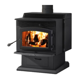
GENERAL INFORMATION 2.1 ENERZONE SOLUTION 3.4 SPECIFICATIONS Model # EB00032 Colour Metallic black Combustible Hardwood Recommended heating area* 370 m Test Standard (safety) AS/NZS 2918 Test Standards (emissions) AS/NZS 4012 /4013/4014.1 Optimum efficiency – hardwood Average efficiency – hardwood Average emissions – hardwood 1.1 g/kg... - Page 8 Solution 3.4 Installation and Operation Manual...
- Page 9 Solution 3.4 Installation and Operation Manual...
-
Page 10: Zone Heating And How To Make It Work For You
2.2 ZONE HEATING AND HOW TO MAKE IT WORK FOR YOU Your new Enerzone Solution 3.4 wood fire is a space heater, which means it is intended to heat the area it is installed in, as well as spaces that connect to that area, although to a lower temperature. -
Page 11: Enerzone's Commitment To You And The Environment
2.4 ENERZONE’S COMMITMENT TO YOU AND THE ENVIRONMENT The Enerzone team is committed to protecting the environment, so we do everything we can to use only materials in our products that will have no lasting negative impact on the environment. -
Page 12: Fuel
3 FUEL 3.1 MATERIALS THAT SHOULD NOT BE BURNED GARBAGE OF ANY KIND, • COAL OR CHARCOAL, • TREATED, PAINTED OR COATED WOOD, • PLYWOOD OR PARTICLE BOARD, • FINE PAPER, COLORED PAPER OR CARDBOARD, • • SALT WATER DRIFTWOOD, •... -
Page 13: Log Length
3.2.3 LOG LENGTH Logs should be cut about 25 mm (1”) shorter than the firebox so they fit in easily. Pieces that are slightly too long make loading the wood fire very difficult. The most common standard length of firewood is 400 mm (16”). The pieces should be a consistent length, with a maximum of 25 mm (1”) variation from piece to piece. -
Page 14: How To Dry Firewood
3.2.5 HOW TO DRY FIREWOOD Firewood that is not dry enough to burn is the cause of most complaints about wood fires. The complaints usually involve a lack of heat and dirty door glass. Here are some things to consider in estimating drying time: firewood takes a long time to dry •... -
Page 15: Judging Firewood Moisture Content
3.2.6 JUDGING FIREWOOD MOISTURE CONTENT You can find out if some firewood is dry enough to burn by using these guidelines: cracks form at the ends of logs as they dry • as it dries in the sun, the wood turns from white or cream coloured to grey or yellow, •... -
Page 16: Operating Your Wood Fire
4 OPERATING YOUR WOOD FIRE NEVER OVERFIRE YOUR WOOD FIRE. IF ANY PART OF THE WOOD FIRE STARTS TO GLOW • RED, OVER FIRING IS HAPPENING. READJUST THE AIR INTAKE CONTROL AT A LOWER SETTING. NEVER LOAD YOUR WOOD FIRE UP TO THE BAFFLE. ALWAYS LEAVE 5 TO 10 CENTIMETERS •... -
Page 17: Conventional Fire Starting
4.2.1 CONVENTIONAL FIRE STARTING The conventional way to build a wood fire is to bunch up 5 to 10 sheets of plain newspaper and place them in the firebox. Next, place 10 or so pieces of fine kindling on the newspaper. This kindling should be very thin;... -
Page 18: Using Fire Starters
4.2.4 USING FIRE STARTERS Many people like to use commercial fire starters instead of newspaper. Some of these starters are made of sawdust and wax and others are specialized flammable solid chemicals. Follow the package directions for use. Gel starter may be used but only if there are no hot embers present. Use only in a cold firebox to start a fire. -
Page 19: Ash Removal
4.3.2 ASH REMOVAL Ash should be removed from the firebox every two or three days of full time heating. Do not let the ash build up in the firebox because it will interfere with proper fire management. The best time to remove ash is after an overnight fire when the wood fire is relatively cool, but there is still some flue system draft to draw the ash dust into the wood fire and prevent it from coming into the room. -
Page 20: Firing Each New Load Hot
4.3.4 FIRING EACH NEW LOAD HOT Place the new load of wood on and behind the charcoal and not too close to the glass. Close the door and open the air control fully. Leave the air control fully open until the firebox is full of flames, the wood has charred to black and its edges are glowing red. -
Page 21: Building Different Fires For Different Needs
4.3.6 BUILDING DIFFERENT FIRES FOR DIFFERENT NEEDS Using the air control is not the only way to match the wood fire’s heat output to the heat demand. Your house will need far less heat in April than in July to be kept at a comfortable temperature. If you fill the firebox full in fall weather, you will either overheat the space or turn the wood fire down so much that the fire will be smoky and inefficient. - Page 22 4.3.6.3 High Output Fires for Cold Weather When the heat demand is high during cold weather, you’ll need a fire that burns steadily and brightly. This is the time to use your biggest pieces of hardwood fuel if you have it. Put the biggest pieces at the back of the firebox and place the rest of the pieces compactly.
-
Page 23: Maintaining Your Wood Heating System
5 MAINTAINING YOUR WOOD HEATING SYSTEM 5.1 WOOD FIRE MAINTENANCE Your new wood fire will give many years of reliable service if you use and maintain it correctly. Some of the internal components of the firebox, such as firebricks, baffles and air tubes, will wear over time under intense heat. -
Page 24: Door Adjustment
5.1.3 DOOR ADJUSTMENT In order for your wood fire to burn at its best efficiency, the door must provide a perfect seal with the firebox. Therefore, the gasket should be inspected periodically making sure to obtain an air tight fit. Airtightness can be improved with a simple latch mechanism adjustment. To increase the pressure on the gasket, remove one washer (A). -
Page 25: Replacing The Door Gasket
5.1.4 REPLACING THE DOOR GASKET It is important to maintain the gasket in good condition. After a year or more of use, the door gasket will compress and become hard, which may allow air to leak past it. You can test the condition of the door gasket by closing and latching the door on a strip of paper. -
Page 26: Cleaning And Painting The Wood Fire
To replace the glass (C), remove the six screws and glass retainers (A) and the metal frames (B). Remove the damaged glass (C) and install the new one in place. Make sure you have a gasket around the replacement glass (see procedure above). -
Page 27: How Often Should You Clean The Flue System
5.2.2 HOW OFTEN SHOULD YOU CLEAN THE FLUE SYSTEM? It is not possible to predict how much or how quickly creosote will form in your flue system. It is important, therefore, to check the build-up in your flue system monthly when getting used to the new wood fire until you determine the rate of creosote formation. -
Page 28: Part B - Installation
PART B – INSTALLATION It is very important to position the wood fire as close as possible to the flue system, and in an area that will favour the most efficient heat distribution possible throughout the house. The wood fire must therefore be installed in the room where the most time is spent, and in the most spacious room possible. -
Page 29: Regulations Covering Wood Fire Installation
6.2 REGULATIONS COVERING WOOD FIRE INSTALLATION IT IS RECOMMENDED THAT THE INSTALLATION OF YOUR ENERZONE WOOD FIRE BE CARRIED OUT BY A QUALIFIED SPECIALIST INSTALLER. IF ANY ELECTRICAL WORK IS REQUIRED, IT MUST BE CARRIED OUT BY A LICENSED ELECTRICIAN. -
Page 30: Clearances To Heat-Sensitive Materials
7 CLEARANCES TO HEAT-SENSITIVE MATERIALS It is of outmost importance that the clearances to heat-sensitive materials be carefully maintained upon installation of the wood fire you have selected. Refer to the tables below. No part of the wood fire or flue may be located closer to combustibles than the minimum clearance figures given. -
Page 31: Floor Protector
Clearances to heat-sensitive materials and floor protection 7.3 FLOOR PROTECTOR If the wood fire is to be installed on top of a combustible floor, it must be guarded by a non combustible material as shown on the dotted line area of the above figures. Install a 850 mm (W) x 1215 mm (D) floor protection of 6 mm of thickness with thermal conductivity of 0.8 m K/W per 4 mm thick. -
Page 32: Reducing Wall And Ceiling Clearances Safely
7.4 REDUCING WALL AND CEILING CLEARANCES SAFELY You may decrease the minimum clearances to heat-sensitive materials by installing heat radiation shields between the walls or the ceiling and the wood fire. These heat radiation shields must be installed permanently, and must be made of a heat-resistant or heat-tolerant material. - Page 33 CONSTRUCTIONS AND CLEARANCES FACTORS FOR APPLIANCES HEAT SHIELDS WHICH ARE MORE THAN 45 OFF THE VERTICAL Minimum air gap HEAT SHIELD CONSTRUCTIONS Clearances factor dimensions (mm) Single layer of continuous material 0.80 Single layer of continuous material 0.60 NOTES: 1- Masonry may be used as a heat shield material. 2- Where heat shields are used to reduce appliance clearance dimensions, additional flue shielding may also be required.
-
Page 34: The Flue System
8 THE FLUE SYSTEM 8.1 GENERAL The flue system, made up of the flue system and the flue between the wood fire and the flue system, acts as the engine that drives your wood heating system. Even the best wood fire will not function safely and efficiently as intended if it is not connected to a suitable flue system. -
Page 35: Masonry Flue Systems
8.2.2 MASONRY FLUE SYSTEMS The wood fire may also be connected to a masonry flue system, provided the flue system complies with AS/NZS 2918 or with the construction rules found in the building code enforced locally. The flue system must have either a clay liner or a suitably listed stainless steel liner. -
Page 36: The Relationship Between The Flue System And The House
The top of the flue system should be tall enough to be above the air turbulence caused when wind blows against the house and its roof. The flue exit shall be located outside the building in which the appliance is installed so that: a) The flue pipe shall extend not less than 4.6 m above the top of the floor protector;... -
Page 37: Why The Flue System Should Penetrate The Highest Heated Space
8.4.2 WHY THE FLUE SYSTEM SHOULD PENETRATE THE HIGHEST HEATED SPACE When it is cold outside, the warm air in the house is buoyant so it tends to rise. This tendency of warm air to rise creates a slight pressure difference in the house. Called ‘stack effect’, it produces a slightly negative pressure low in the house (relative to outside) and a slightly positive pressure zone high in the house. - Page 38 Use 45 degree elbows where possible, instead of 90 degree elbows. Solution 3.4 Installation and Operation Manual...
- Page 39 The rules below are based on those found in the AS/NZS 2918:2001 installation code. Please carefully follow these installation instruction rules, or those enforced where you live. Maximum overall length of straight flue system: not less than 4.6 m above the top of the floor •...
-
Page 40: Appendix 1: Installing The Door Overlay
APPENDIX 1: INSTALLING THE DOOR OVERLAY Your Enerzone Solution 3.4 wood fire must be equipped with a door overlay. In order to install it, secure it to the door using 4 screws (#8 – 32 x 5/8’’ pan quadrex), supplied with the owner’s manual) as shown below. -
Page 41: Appendix 2: Installing The Decorative Panels
APPENDIX 2: INSTALLING THE DECORATIVE PANELS 1. Remove the rear screws (A) holding side shields (B) onto the wood fire. 2. Remove the protective film on the four decorative accents. 3. Install all four decorative accents from within the side shields. 4. -
Page 42: Appendix 3: Installation And Use Of The Blower And Thermodisc
APPENDIX 3: INSTALLATION AND USE OF THE BLOWER AND THERMODISC An optional blower (AC01010) can be installed on the back of the wood fire to increase the flow of air past heat exchange surfaces and to help circulate warm air in the room. When used regularly, the blower can provide a small increase in efficiency, up to 2 percent. - Page 43 Before turning-on blower, allow the wood fire reach operating temperature (approximately one hour). The increased airflow from the blower cools the firebox and could affect start-up combustion efficiency if the blower is turned on too early. You can also install a thermodisc (A) to enable the blower to start or stop automatically...
-
Page 44: Appendix 4: Installation Of Secondary Air Tubes And Baffle
APPENDIX 4: INSTALLATION OF SECONDARY AIR TUBES AND BAFFLE 1. Remove cotter pin at LH end of tube. 2. Slide tube to right and lower tube end below LH plenum. 3. Slide tube to left to remove. 4. Reassemble in reverse order using a new cotter pin. The cotter pin is a hammerlock style and locks into place by hitting the head sharply with a hammer. - Page 45 Step 1: Start by taking out the four firebricks on the right hand side of the firebox then remove the cotter pins and the secondary air tubes from the wood fire making sure to identify them so they can be reinstalled in the same location.
- Page 46 Step 3: Repeat step 2 for the second baffle and insulation. Step 4: Reinstall the secondary air tubes and cotter pins in their original location and put the four right hand side firebricks back into place. Solution 3.4 Installation and Operation Manual...
- Page 47 The air tubes are identified for placement as follows: Model Type of tube Front ► 28 holes of 5.15mm Enerzone Solution 3.4 Middle ► 28 holes of 4.36mm (Painted red) Rear ► 28 holes of 4.36mm (Painted yellow) Solution 3.4 Installation and Operation Manual...
-
Page 48: Appendix 5: Exploded Diagram And Parts List
APPENDIX 5: EXPLODED DIAGRAM AND PARTS LIST Solution 3.4 Installation and Operation Manual... - Page 49 IMPORTANT: THIS IS DATED INFORMATION. When requesting service or replacement parts for your wood fire, please provide the model number and the serial number. We reserve the right to change parts due to technology upgrade or availability. Contact an authorized dealer to obtain any of these parts.
- Page 50 Item Description 60196 POWER CORD RECEPTACLE 44085 RHEOSTAT KNOB 44087 RHEOSTAT NUT PL44043 RHEOSTAT 240v Australian 44088 TANGENTIAL BLOWER LOW PROFIL 240V-50Hz (B) AC02056 QUICK CONNECT THERMODISC KIT AC05530 THERMODISC KIT 44028 CERAMIC THERMODISC F110-20F 24096 ROUND CAST IRON ASH PLUG 29020 4 1/2'' X 9'' X 1 1/4'' REFRACTORY BRICK HD PL36048...
-
Page 51: Enerzone Product Warranty
(with each of the below periods commencing on the date the Enerzone product was purchased by you as a brand new product from a retailer located in Australia): WARRANTY APPLICATION... - Page 52 Goods presented for repair may be replaced by refurbished goods of the same type rather than being repaired. Refurbished parts may be used to repair the goods. Enerzone products are designed and supplied for normal domestic use. We will not be liable to you under this warranty for business loss or damage of any kind whatsoever.
Need help?
Do you have a question about the EB00032 and is the answer not in the manual?
Questions and answers