Daikin CTXU25G2V1B Service Manual
Inverter multi system with humidifying
Hide thumbs
Also See for CTXU25G2V1B:
- Service manual (175 pages) ,
- Operation manual (37 pages) ,
- Installation manual (18 pages)

Related Manuals for Daikin CTXU25G2V1B


Summary of Contents for Daikin CTXU25G2V1B
- Page 1 SiBE12-908 Inverter Multi System with Humidifying G-Series [Applied Models] Inverter Multi : Heat Pump...
- Page 2 SiBE12-908 Inverter Multi System with Humidifying G-Series Heat Pump Indoor Unit CTXU25G2V1B CTXU35G2V1B CTXU42G2V1B CTXU50G2V1B Outdoor Unit 2MXU40GV1B 2MXU50GV1B Table of Contents...
-
Page 3: Table Of Contents
SiBE12-908 1. Introduction .................... vi 1.1 Safety Cautions ..................vi 1.2 Used Icons ....................x Part 1 List of Functions ..............1 1. Functions....................2 Part 2 Specifications ..............4 1. Specifications ..................5 1.1 Indoor Units ....................5 1.2 Outdoor Units ...................6 Part 3 Printed Circuit Board Connector Wiring Diagram ..... 8 1. - Page 4 SiBE12-908 3.14 Forced Operation Mode .................53 3.15 Additional Function.................53 Part 5 Installation / Operation Manual ........54 1. Installation Manual ................55 1.1 Indoor Units ....................55 1.2 Outdoor Units ..................67 2. System Configuration................79 3. Operation Manual..................80 3.1 Names of Parts..................80 3.2 AUTO · DRY · COOL · HEAT · FAN Operation ........82 3.3 Adjusting the Airflow Direction..............84 3.4 HUMID HEAT Operation ................86 3.5 FRESH AIR SUPPLY VENTILATION ............88...
- Page 5 SiBE12-908 2.24 Damper Abnormality................142 2.25 Position Sensor Abnormality ..............143 2.26 DC Voltage / DC Current Sensor Abnormality ........145 2.27 Thermistor or Related Abnormality (Outdoor Unit).......146 2.28 Abnormal Temperature in Electrical Box..........148 2.29 Temperature Rise in Radiation Fin............150 2.30 Output Overcurrent................152 2.31 Refrigerant Shortage ................154 2.32 Over Voltage Protection / Low Voltage Protection .......156 2.33 Outdoor Unit PCB Abnormality or...
- Page 6 SiBE12-908 2.5 Removal of the Fan-valve-duct ASSY..........225 2.6 Removal of Hygroscopic Fan Rotor / Hygroscopic Fan Motor .....227 2.7 Removal of Panels and Plates .............228 2.8 Removal of Electrical Box ..............231 2.9 Removal of PCB...................236 2.10 Removal of Sound Blanket..............242 2.11 Removal of the Propeller Fan / Fan Motor ...........245 2.12 Removal of Thermistors ...............248 2.13 Removal of Compressor...............250...
-
Page 7: Introduction
SiBE12-908 Introduction 1. Introduction Safety Cautions Cautions and Be sure to read the following safety cautions before conducting repair work. The caution items are classified into “ Warning” and “ Caution”. The “ Warning” Warnings items are especially important since they can lead to death or serious injury if they are not followed closely. - Page 8 Introduction SiBE12-908 Warning Be sure to wear a safety helmet, gloves, and a safety belt when working at a high place (more than 2m). Insufficient safety measures may cause a fall accident. In case of R410A refrigerant models, be sure to use pipes, flare nuts and tools for the exclusive use of the R410A refrigerant.
- Page 9 SiBE12-908 Introduction 1.1.2 Cautions Regarding Safety of Users Warning Be sure to use parts listed in the service parts list of the applicable model and appropriate tools to conduct repair work. Never attempt to modify the equipment. The use of inappropriate parts or tools may cause an electrical shock, excessive heat generation or fire.
- Page 10 Introduction SiBE12-908 Warning Check to make sure that the power cable plug is not dirty or loose, then insert the plug into a power outlet securely. If the plug has dust or loose connection, it may cause an electrical shock or fire. Be sure to install the product correctly by using the provided standard For unitary type installation frame.
-
Page 11: Used Icons
SiBE12-908 Introduction Caution Be sure to measure the insulation resistance after the repair, and make sure that the resistance is 1 MΩ or higher. Faulty insulation may cause an electrical shock. Be sure to check the drainage of the indoor unit after the repair. Faulty drainage may cause the water to enter the room and wet the furniture and floor. -
Page 12: Part 1 List Of Functions
SiBE12-908 Part 1 List of Functions 1. Functions....................2 List of Functions... -
Page 13: Functions
SiBE12-908 Functions 1. Functions Category Functions Category Functions Basic Inverter (with Inverter Power Control) Health & Air-Purifying Filter — Function Clean Operation Limit for Cooling (°CDB) — Operation Limit for Heating (°CWB) — Photocatalytic Deodorizing Filter — Air-Purifying Filter with Photocatalytic PAM Control —... - Page 14 Functions SiBE12-908 Category Functions Category Functions Basic Inverter (with Inverter Power Control) Health & Air-Purifying Filter — Function Clean Operation Limit for Cooling (°CDB) Photocatalytic Deodorizing Filter — –15 Air-Purifying Filter with Photocatalytic Operation Limit for Heating (°CWB) — Deodorizing Function 15.5 Titanium Apatite Photocatalytic PAM Control...
-
Page 15: Part 2 Specifications
SiBE12-908 Part 2 Specifications 1. Specifications ..................5 1.1 Indoor Units ....................5 1.2 Outdoor Units ...................6 Specifications... -
Page 16: Specifications
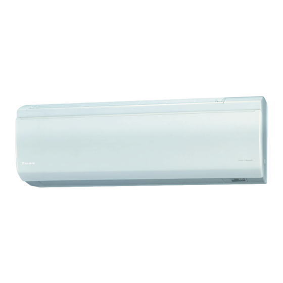
Specifications SiBE12-908 1. Specifications Indoor Units 50Hz 220-230-240V CTXU25G2V1B CTXU35G2V1B Model Cooling Heating Cooling Heating Rated Capacity 2.5kW Class 3.5kW Class Front Panel Color White White 9.1 (321) 9.8 (346) 10.4 (367) 10.6 (374) 7.1 (252) 7.9 (280) 7.7 (270) 8.5 (302) -
Page 17: Outdoor Units
SiBE12-908 Specifications Outdoor Units 50Hz 220-230-240V 2MXU40GV1B Model Cooling Heating Capacity — Power Consumption — Running Current — Casing Color Ivory White Type Hermetically Sealed Swing Type Compressor Model 1YC23ABXD Motor Output Model FVC50K Refrigerant Oil Charge 0.45 Type R-410A Refrigerant Charge 1.20... - Page 18 Specifications SiBE12-908 50Hz 220-230-240V 2MXU50GV1B Model Cooling Heating — Capacity — Power Consumption — Running Current Casing Color Ivory White Type Hermetically Sealed Swing Type Compressor Model 2YC36BXD Motor Output 1,100 Model FVC50K Refrigerant Oil Charge 0.65 Type R-410A Refrigerant Charge 1.60 m³/min...
-
Page 19: Part 3 Printed Circuit Board Connector Wiring Diagram
SiBE12-908 Part 3 Printed Circuit Board Connector Wiring Diagram 1. Printed Circuit Board Connector Wiring Diagram........9 1.1 Indoor Units ....................9 1.2 Outdoor Units ..................11 Printed Circuit Board Connector Wiring Diagram... -
Page 20: Printed Circuit Board Connector Wiring Diagram
Printed Circuit Board Connector Wiring Diagram SiBE12-908 1. Printed Circuit Board Connector Wiring Diagram Indoor Units Connectors PCB(1) (Control PCB) 1) S1 Connector for DC fan motor 2) S21 Connector for centralized control (HA) 3) S25 Connector for INTELLIGENT EYE sensor PCB 4) S32 Connector for heat exchanger thermistor 5) S41... - Page 21 SiBE12-908 Printed Circuit Board Connector Wiring Diagram PCB Detail PCB(1): Control PCB LED A (R10337) PCB(2): Signal Receiver PCB PCB(3): Display PCB RTH1 LED3 LED2 LED1 Humidity sensor (R9996) (R9997) PCB(4): INTELLIGENT EYE sensor PCB 3EB86013 Printed Circuit Board Connector Wiring Diagram...
-
Page 22: Outdoor Units
Printed Circuit Board Connector Wiring Diagram SiBE12-908 Outdoor Units Connectors PCB (1) (Control PCB) 1) S20 Connector for electronic expansion valve coil A port 2) S21 Connector for electronic expansion valve coil B port 3) S22 Connector for damper motor 4) S23 Connector for rotor motor 5) S40... - Page 23 SiBE12-908 Printed Circuit Board Connector Wiring Diagram PCB Detail PCB (1): Control PCB S501 LED A (R10338) Printed Circuit Board Connector Wiring Diagram...
-
Page 24: Part 4 Function And Control
SiBE12-908 Part 4 Function and Control 1. Main Functions..................14 1.1 Frequency Principle................14 1.2 Thermostat Control.................16 1.3 Automatic Operation................17 1.4 Program Dry Function ................18 1.5 Airflow Direction Control.................19 1.6 Fan Speed Control for Indoor Units............20 1.7 HUMID HEAT Operation ................21 1.8 Fresh Air Supply Ventilation ..............26 1.9 2-AREA INTELLIGENT EYE ..............28 1.10 Inverter POWERFUL Operation .............30 1.11 ECONO Mode ..................31... -
Page 25: Main Functions
SiBE12-908 Main Functions 1. Main Functions Frequency Principle Main Control The compressor is frequency-controlled during normal operation. The target frequency is set by the following 2 parameters coming from the operating indoor unit: Parameters The load condition of the operating indoor unit The difference between the room temperature and the set temperature Additional The target frequency is adapted by additional parameters in the following cases:... - Page 26 Main Functions SiBE12-908 Inverter Features The inverter provides the following features: The regulating capacity can be changed according to the changes in the outdoor air temperature and cooling / heating load. Quick heating and quick cooling The compressor rotational speed is increased when starting the heating (or cooling). This enables a quick set temperature.
-
Page 27: Thermostat Control
SiBE12-908 Main Functions Thermostat Control Thermostat control is based on the difference between the room temperature and the set point. Thermostat OFF Condition The temperature difference is in the zone A. Thermostat ON Condition The temperature difference is above the zone C after being in the zone A. The system resumes from defrost control in any zones except A. -
Page 28: Automatic Operation
Main Functions SiBE12-908 Automatic Operation Automatic Cooling / Heating Function When the AUTO mode is selected with the remote controller, the microcomputer automatically determines the operation mode from cooling and heating according to the room temperature and setting temperature at the time of the operation startup, and automatically operates in that mode. -
Page 29: Program Dry Function
SiBE12-908 Main Functions Program Dry Function Program dry function removes humidity while preventing the room temperature from lowering. Since the microcomputer controls both the temperature and airflow volume, the temperature adjustment and fan adjustment buttons are inoperable in this mode. In Case of The microcomputer automatically sets the temperature and fan settings. -
Page 30: Airflow Direction Control
Main Functions SiBE12-908 Airflow Direction Control Power-Airflow The large flaps send a large volume of air downwards to the floor. The flap provides an optimum control area in cooling, heating, and dry mode. Dual Flaps Heating Mode During heating mode, the large flap enables direct warm air straight downwards. The flap presses the warm air above the floor to reach the entire room. -
Page 31: Fan Speed Control For Indoor Units
SiBE12-908 Main Functions Fan Speed Control for Indoor Units Control Mode The airflow rate can be automatically controlled depending on the difference between the set temperature and the room temperature. This is done through phase control and Hall IC control. For more information about Hall IC, refer to the troubleshooting for fan motor on page 123. -
Page 32: Humid Heat Operation
Main Functions SiBE12-908 HUMID HEAT Operation Operation 1. Select HEAT mode. 2. Set humidity. (R9409) ∗ Refer to the operation manual for details. Features The-world’s first new humidifying method has adopted What is new in this method is to intake vapor in the outdoor air with the hygroscopic element mounted in outdoor unit, and send to indoors. - Page 33 SiBE12-908 Main Functions • HUMID HEAT operation by URURU This air conditioner enables uniformly humidifying the room by circulating vapor with warm air. The room is uniformly humidified. (R3326) Powerful humidifying ability The humidifying capacity is 450 ml/h and equivalent to that of a normal humidifier. The value is measured at 7°C DB / 6°C WB of outdoor air and with 4.0 m of humidifying hose length.
- Page 34 Main Functions SiBE12-908 How to Check the You can check whether the humidifying unit is in good working order. If you set HUMID HEAT test operation (refer to the installation manual for details), you can check even beyond the range Motion of of the conditions for humidifying operation.
- Page 35 SiBE12-908 Main Functions Time chart for Approx. 1 minute after HUMID HEAT operation start up, it repeats humidifying and drying alternately (to protect condensation for inside the hose). humidifying operation control HUMID HEAT Approx. 1min operation Approx. 3min Humidifying fan and damper Hygroscopic 15 sec.
- Page 36 Main Functions SiBE12-908 Humidification The humidifying of this system is different from that of the normal humidifier. Therefore, the humidifying performance varies with the outdoor temperature or installation condition. performance by Sufficient humidifying capacity may not be attained depending on the weather condition in outdoor operation.
-
Page 37: Fresh Air Supply Ventilation
SiBE12-908 Main Functions FRESH AIR SUPPLY VENTILATION Operation FRESH AIR SUPPLY VENTILATION (R9425) ∗ Refer to the operation manual for details. Features The air supply ventilation system using only fresh air. Any contaminated outdoor air is purified in two stages of indoor unit and outdoor unit. Fresh air from which pollen and dust were removed is supplied into the room. - Page 38 Main Functions SiBE12-908 Ventilation System The ventilation type is mainly divided into two. The convenient system is supply ventilation. Exhaust Ventilation Supply Ventilation Fresh Air Supply Draft (R5979) - Quiet because the ventilation fan is located in - Operation noise is heard because the ventilation the outdoor unit fan is located in the room.
-
Page 39: 2-Area Intelligent Eye
SiBE12-908 Main Functions 2-AREA INTELLIGENT EYE The following functions can be performed by a human motion sensor (INTELLIGENT EYE). 1. Reduces the capacity when there is no human in the room in order to save electricity. (energy saving operation) 2. Divides the room into plural areas and detects existence of humans in each area. Shifts the airflow direction to the area having no human automatically to avoid direct airflow on humans. - Page 40 Main Functions SiBE12-908 2. The motions in energy saving operation (for example: in cooling) within 20 minutes. 20 min. 20 min. Human detection signal RESET. (From area A or B) Cooling : Set temp. + 2°C Heating : Set temp. – 2°C Set temp.
-
Page 41: Inverter Powerful Operation
SiBE12-908 Main Functions 1.10 Inverter POWERFUL Operation Outline In order to exploit the cooling and heating capacity to full extent, operate the air conditioner by increasing the indoor fan rotating speed and the compressor frequency. Details of the When POWERFUL button is pushed in each operation mode, the fan speed and set temperature are converted to the following states in a period of 20 minutes. -
Page 42: Econo Mode
Main Functions SiBE12-908 1.11 ECONO Mode Outline The "ECONO mode" reduces the maximum operating current and power consumption by approx. 30% during start up etc.. This mode is particularly convenient for energy-saving-oriented users. It is also a major bonus for those whose breaker capacities do not allow the use of multiple electrical devices and air conditioners. -
Page 43: Night Set Mode
SiBE12-908 Main Functions 1.12 NIGHT SET Mode When the OFF timer is set, the NIGHT SET circuit automatically activates. The NIGHT SET circuit maintains the airflow setting made by users. The NIGHT SET The NIGHT SET circuit continues heating or cooling the room at the set temperature for the first Circuit one hour, then automatically raises the temperature setting slightly in the case of cooling, or lowers it slightly in the case of heating, for economical operations. -
Page 44: Other Functions
Main Functions SiBE12-908 1.13 Other Functions 1.13.1 Multi-Colored Indicator Lamp Features Current operation mode is displayed in color of the lamp of the indoor unit which changes in 6 colors. Operating status can be monitored even in automatic operation in accordance with the content of actual operation. - Page 45 SiBE12-908 Main Functions 1.13.5 ON/OFF Button on Indoor Unit An ON/OFF button is provided on the front panel of the unit. Use this button when the remote controller is missing or if its battery has run out. Every press of the button switches from ON to OFF or from OFF to ON. ON/OFF button ON / OFF (R9408)
-
Page 46: Table For Special Modes
Main Functions SiBE12-908 1.14 Table for Special Modes Indoor [ON/OFF] 5~9 sec. • Indoor [ON/OFF] Forced operation mode • Left for 15 min. [CANCEL] 5 sec. • [CANCEL] 5 sec. Easy diagnosis mode • Left for 60 sec. Mode selection view: Select with TEMP button. - Page 47 SiBE12-908 Main Functions 2. Trial operation mode: You can select a mode for trial operation on the remote controller. The operation continues for approx. 30 minutes. Refer to the installation manual on page 66 for detail. 3. Pipe set mode: You can set the humidifying hose length and then check the preset value.
-
Page 48: Function Of Thermistor
Function of Thermistor SiBE12-908 2. Function of Thermistor Heat Pump Model Expansion valve Four way valve (R7042) Compressor A Outdoor Heat 1. The outdoor heat exchanger thermistor is used for controlling target discharge pipe temperature. Exchanger The system sets a target discharge pipe temperature according to the outdoor and indoor Thermistor heat exchanger temperature, and controls the electronic expansion valve opening so that the target discharge pipe temperature can be obtained. - Page 49 SiBE12-908 Function of Thermistor D Indoor Heat 1. The indoor heat exchanger thermistors are used for controlling target discharge pipes temperature. Exchanger The system sets a target discharge pipe temperature according to the outdoor and indoor Thermistor heat exchanger temperature, and controls the electronic expansion valve opening so that the target discharge pipes temperature can be obtained.
-
Page 50: Control Specification
Control Specification SiBE12-908 3. Control Specification Mode Hierarchy Outline There are two modes; the mode selected in user’s place (normal air conditioning mode) and forced operation mode for installation and providing service. Detail There are following modes; stop, cooling (includes drying), heating (include defrosting) Air conditioner control mode Forced operating mode Forced cooling (for Pump Down Operation) -
Page 51: Automatic Switching For Humid Heat Operation Room
SiBE12-908 Control Specification Automatic switching for HUMID HEAT operation room Outline When the indoor units in both 2 rooms are set to HUMID HEAT operation, priority is given to the indoor unit starting operation first basically. However, priority is given to the indoor unit starting operation subsequently under certain conditions. -
Page 52: Frequency Control
Control Specification SiBE12-908 Frequency Control Outline Frequency that corresponds to each room’s capacity is determined according to the difference in the temperature of each room and the temperature that is set by the remote controller. The function is explained as follows. 1. - Page 53 SiBE12-908 Control Specification Indoor Frequency Command ( ∆ D signal) The difference between a room temperature and the temperature set by the remote controller is taken as the “ ∆ D signal” and is used for frequency command. ∆D ∆D ∆D ∆D Temperature...
-
Page 54: Controls At Mode Changing / Start-Up
Control Specification SiBE12-908 Controls at Mode Changing / Start-up 3.4.1 Preheating Operation Outline Operate the inverter in the open phase operation with the conditions including the preheating command from the indoor, the outdoor air temperature and discharge pipe temperature. Detail Preheating ON Condition When outdoor air temperature is below 10.5ºC and discharge pipe temperature is below 10.5ºC, inverter in open phase operation starts. -
Page 55: Discharge Pipe Temperature Control
SiBE12-908 Control Specification 3.4.5 Compressor Protection Function When turning the compressor from OFF to ON, the upper limit of frequency must be set as follows. (The function must not be used when defrosting.) 40 class 50 class (Hz) Frequency FCG 1 FCG 2 FCG3 FCG2... -
Page 56: Input Current Control
Control Specification SiBE12-908 Input Current Control Outline Detect an input current by the CT during the compressor is running, and set the frequency upper limit from such input current. In case of heat pump model, this control is the upper limit control function of the frequency which takes priority of the lower limit of four way valve activating compensation. -
Page 57: Heating Peak-Cut Control
SiBE12-908 Control Specification Heating Peak-cut Control Outline During heating operation, the signals being sent from the indoor unit allow the operating frequency limitation and prevent abnormal high pressure. (The signal from the indoor unit must be divided as follows.) Detail Conditions for Start Controlling Judge the controlling start with the indoor heat exchanger temperature after 2 minutes from operation start and... -
Page 58: Liquid Compression Protection Function 2
Control Specification SiBE12-908 3.10 Liquid Compression Protection Function 2 Outline In order to obtain the dependability of the compressor, the compressor must be stopped according to the conditions of the temperature of the outdoor air and outdoor heat exchanger. Detail Operation stops depending on the outdoor air temperature. -
Page 59: Electronic Expansion Valve Control
SiBE12-908 Control Specification 3.12 Electronic Expansion Valve Control Outline The following items are included in the electronic expansion valve control. Electronic expansion valve is fully closed 1. Electronic expansion valve is fully closed when turning on the power. 2. Pressure equalizing control Room Distribution Control 1. - Page 60 Control Specification SiBE12-908 Detail The followings are the examples of control which function in each mode by the electronic expansion valve control. Operation pattern : function × : not function When power is turned ON × × × × × ×...
- Page 61 SiBE12-908 Control Specification 3.12.1 Fully Closing with Power On Initialize the electronic expansion valve when turning on the power, set the opening position and develop pressure equalizing. 3.12.2 Pressure Equalization Control When the compressor is stopped, open and close the electronic expansion valve and develop pressure equalization.
- Page 62 Control Specification SiBE12-908 Detail Detect Disconnection If a 720-second timer for open control becomes over, the following adjustment must be made. 1. When the operation mode is cooling When the discharge pipe temperature is lower than the outdoor heat exchanger temperature, the discharge pipe thermistor disconnection must be ascertained.
-
Page 63: Malfunctions
SiBE12-908 Control Specification 3.13 Malfunctions 3.13.1 Sensor Malfunction Detection Sensor malfunction may occur either in the thermistor or current transformer (CT) system. Relating to Thermistor Malfunction 1. Outdoor heat exchanger thermistor 2. Discharge pipe thermistor 3. Fin thermistor 4. Gas pipe thermistor 5. -
Page 64: Forced Operation Mode
Control Specification SiBE12-908 Detail Judgment by Input Current When an output frequency is exceeds 51 Hz (40 class) or 48 Hz (50 class) and the input current is less than specified value, the adjustment is made for refrigerant shortage. Judgment by Discharge Pipe Temperature When discharge pipe temperature is higher than certain value and the electronic expansion value opening is 450 pulse (max.), the adjustment is made for refrigerant shortage. -
Page 65: Part 5 Installation / Operation Manual
SiBE12-908 Part 5 Installation / Operation Manual 1. Installation Manual ................55 1.1 Indoor Units ....................55 1.2 Outdoor Units ..................67 2. System Configuration................79 3. Operation Manual..................80 3.1 Names of Parts..................80 3.2 AUTO · DRY · COOL · HEAT · FAN Operation ........82 3.3 Adjusting the Airflow Direction..............84 3.4 HUMID HEAT Operation ................86 3.5 FRESH AIR SUPPLY VENTILATION ............88... -
Page 66: Installation Manual
Installation Manual SiBE12-908 1. Installation Manual Indoor Units Indoor Unit Installation Drawings How to attach the indoor unit. Mounting Hook the claws of the bottom frame plate to the mounting plate. If the claws are difficult to hook, remove the front grille. Mounting plate Clip How to remove the indoor unit. - Page 67 SiBE12-908 Installation Manual Preparation before Installation 1. Removing and installing front panel. • Removal method Hook fingers on the tabs on the left and right of the main body, and open until the panel stops. Slide the front panel sideways to disengage the rotating shaft.
- Page 68 Installation Manual SiBE12-908 Preparation before Installation 3. How to set the different addresses. When 2 indoor units are installed in 1 room, the 2 wireless remote controllers can be set for different addresses. 1) Remove the metal plate electrical wiring cover. (Refer to the Removal/attachment methods of metal plate electrical wiring covers.) 2) Cut the address jumper (JA) on the printed...
- Page 69 SiBE12-908 Installation Manual • Attachment methods of metal plate electrical wiring covers Attach the metal plate electrical wiring covers as shown below. 1) Lean the metal plate electrical wiring cover as shown in the figure and attach tab (1) on the lower side to the electrical wiring box.
- Page 70 Installation Manual SiBE12-908 Refrigerant Piping Work 2. Refrigerant piping. CAUTION 1) Use the flare nut fixed to the main unit. (To prevent cracking of the flare nut by aged deterioration.) 2) To prevent gas leakage, apply refrigeration oil only to the inner surface of the flare. (Use refrigeration oil for R410A.) 3) Use torque wrenches when tightening the flare nuts to prevent damage to the flare nuts and gas leakage.
- Page 71 SiBE12-908 Installation Manual Indoor Unit Installation 1. Installing the mounting plate. • The mounting plate should be installed on a wall which can support the weight of the indoor unit. 1) Temporarily secure the mounting plate to the wall, make sure that the panel is completely level, and mark the boring points on the wall.
- Page 72 Installation Manual SiBE12-908 Indoor Unit Installation 3. Inter-unit wiring. Hang indoor unit’s hook here. 1) Open the front panel, then remove the service lid. 2) Pass the inter-unit wiring from the outdoor unit through the feed- through wall hole and then through the back of the indoor unit. Pull them through the front side.
- Page 73 SiBE12-908 Installation Manual 5. Laying piping, hoses, and wiring. • Connect the humidifying hose to the indoor unit duct. See 4. Humidifying hose installation work for details. Piping bundle diagram • Lay the piping, drain hose and humidifying hose Inter-unit wiring Gas pipe according to the orientation of the piping coming out of Drain hose...
- Page 74 Installation Manual SiBE12-908 Indoor Unit Installation • Left-side piping • Left-back piping • Left-bottom piping Humidifying hose Refrigerant pipe Drain hose Cut out the piping-through hole. Cut out the piping-through hole. Refrigerant pipe Refrigerant pipe Humidifying hose 1) Replace the drain plug and drain hose. (How to replace the drain plug and drain hose.) 2) Pull in the refrigerant piping and lay it so that it matches the liquid and gas piping marked on the mounting plate.
- Page 75 SiBE12-908 Installation Manual 6. Wiring. , install as described in the installation manual supplied with the multi outdoor With a multi indoor unit unit. 1) Strip wire ends (15mm). 2) Match wire colours with terminal numbers on indoor and outdoor unit’s terminal blocks and firmly screw wires to the corresponding terminals.
- Page 76 Installation Manual SiBE12-908 Setting the Humidifying Hose Length CAUTION If the humidifying hose length is not set or it is set incorrectly, the humidifying capacity may diminish or strange sound may occur from humidifying hose. 1. Setting the humidifying hose length. Set the humidifying hose length to ensure humidifying capacity.
- Page 77 SiBE12-908 Installation Manual Trial Operation and Testing 1. Trial operation and testing. 1-1 Measure the supply voltage and make sure that it falls in the specified range. 1-2 Trial operation should be carried out in either cooling or heating mode. •...
-
Page 78: Outdoor Units
Installation Manual SiBE12-908 Outdoor Units Outdoor Unit Installation Drawings 1. Precautions for humidifying hose installation work. • Moisture on the outdoor unit is brought to the indoor unit together with air around the outdoor unit during humidifying operation. Install the outdoor unit in a clean and calm location. •... - Page 79 SiBE12-908 Installation Manual Installation • Install the unit horizontally. • The unit may be installed directly on a concrete verandah or a solid place if drainage is good. • If the vibration may possibly be transmitted to the building, use a vibration-proof rubber (field supply). 1.
- Page 80 Installation Manual SiBE12-908 Outdoor Unit Installation Guideline • Where a wall or other obstacle is in the path of outdoor unit’s intake or exhaust airflow, follow the installation guidelines below. • For any of the below installation patterns, the wall height on the exhaust side should be 1200mm or less. Walls facing two sides Wall facing one side More than 50...
- Page 81 SiBE12-908 Installation Manual Refrigerant Piping Work 1. Installing outdoor unit. 1) When installing the outdoor unit, refer to “Outdoor Unit Installation Drawings” on page 3. 2) If drain work is necessary, follow the procedures below. 2. Drain work. Drain-water hole 1) Use C drain plug for drainage.
- Page 82 Installation Manual SiBE12-908 Refrigerant Piping Work 4. Purging air and checking gas leakage. WARNING 1) Do not mix any substance other than the specified refrigerant (R410A) into the refrigeration cycle. 2) When refrigerant gas leaks occur, ventilate the room as soon and as much as possible. 3) R410A, as well as other refrigerants, should always be recovered and never be released directly into the environment.
- Page 83 SiBE12-908 Installation Manual 5. Refilling the refrigerant. Check the type of refrigerant to be used on the machine nameplate. Precautions when adding R410A Fill from the liquid pipe in liquid form. It is a mixed refrigerant, so adding it in gas form may cause the refrigerant composition to change, preventing normal operation. 1) Before filling, check whether the cylinder has a siphon attached or not.
- Page 84 Installation Manual SiBE12-908 Refrigerant Piping Work Precautions for Laying Refrigerant Piping Wall Be sure to place a cap. Rain If no flare cap is • Cautions on pipe handling available, cover the flare mouth 1) Protect the open end of the pipe against dust and moisture. with tape to keep 2) All pipe bends should be as gentle as possible.
-
Page 85: Pump Down Operation
SiBE12-908 Installation Manual Pump Down Operation In order to protect the environment, be sure to pump down when relocating or disposing of the unit. 1) Remove the valve caps on the liquid and the gas stop valves at the pipes for Liquid Hexagonal rooms A and B. - Page 86 Installation Manual SiBE12-908 Connecting the Humidifying Hose 1. Connecting to indoor unit. Keep the following items in mind in order to prevent the degrading of humidification performance when connecting the humidifying hose to the indoor unit. 1) Cut the excessive portions of the humidifying hoses. * Determine the overall length of the humidifying hoses according to the installation manual for the indoor unit.
- Page 87 SiBE12-908 Installation Manual 2. Connecting to outdoor unit. There are 2 ways to connect humidifying hoses to the outdoor unit. Connecting through the path under the humidifying hoses cover <Back side> 1) Connect the humidifying hose (2m) to the humidifying duct on the back of the outdoor unit.
- Page 88 Installation Manual SiBE12-908 Wiring WARNING 1) Do not use tapped wires, stranded wires (CAUTION 1)), extension cords, or starburst connections, as they may cause overheating, electrical shock, or fire. 2) Do not use locally purchased electrical parts inside the product. (Do not branch the power for the drain pump, etc., from the terminal block.) Doing so may cause electric shock or fire.
- Page 89 SiBE12-908 Installation Manual Test Run and Final Check • Before starting the test run, measure the voltage at the primary side of the safety breaker. • Check that all liquid and gas stop valves are fully open. • Check that piping and wiring all match. 1.
-
Page 90: System Configuration
System Configuration SiBE12-908 2. System Configuration After the installation and test operation of the room air conditioner have been completed, it should be operated and handled as described below. Every user would like to know the correct method of operation of the room air conditioner, to check if it is capable of cooling (or heating) well, and to know a clever method of using it. -
Page 91: Operation Manual
SiBE12-908 Operation Manual 3. Operation Manual Names of Parts Name of Parts Indoor Unit Indoor Unit 1.Air filter 2.Titanium apatite photocatalytic air-purifying filter: • These filters are attached to the inside of the air filters. 3.Air inlet 4.Front panel 5.Panel tab 6.Room temperature and humidity sensors: •... - Page 92 Operation Manual SiBE12-908 Remote Controller Remote Controller 1.Signal transmitter: • It sends signals to the indoor unit. 2.Display (LCD): • It displays the current settings. (In this illustration, each section is shown with its displays ON for the purpose of explanation.) 3.FAN setting button: •...
-
Page 93: Auto · Dry · Cool · Heat · Fan Operation
SiBE12-908 Operation Manual AUTO · DRY · COOL · HEAT · FAN Operation AUTO · DRY · COOL · HEAT · FAN Operation The air conditioner operates with the operation mode of your choice. From the next time on, the air conditioner will operate with the same operation mode. To start operation 1. - Page 94 Operation Manual SiBE12-908 To change the airflow rate setting 5. Press “FAN setting” button. DRY mode AUTO or COOL or HEAT or FAN mode Five levels of airflow rate setting from “ ” to “ ” plus “ ” and “ ”...
-
Page 95: Adjusting The Airflow Direction
SiBE12-908 Operation Manual Adjusting the Airflow Direction Adjusting the Airflow Direction You can adjust the airflow direction to increase your comfort. Adjusting the upper and lower airflow direction To adjust the flaps (horizontal blades) 1. Press “SWING ” button. • “ ”... - Page 96 Operation Manual SiBE12-908 Adjusting the 3-D airflow direction To start 3-D airflow 1. 3. Press the “SWING ” button and the “SWING ” button: the “ ” and “ ” display will light up and the flap and louvers will move in turn. To cancel 3-D airflow 2.
-
Page 97: Humid Heat Operation
SiBE12-908 Operation Manual HUMID HEAT Operation HUMID HEAT Operation This function enables the humidification of a room where the air conditioner is in HEAT operation, thus providing appropriate humidity to the room if the function is used in wintertime during which the air is dry. When the humidity of the room is high, the user will feel warm enough even if the set temperature is dropped. - Page 98 Operation Manual SiBE12-908 NOTE Notes on “HUMID HEAT operation” at multi system • When the indoor units in both 2 rooms are set to HUMID HEAT operation/FRESH AIR SUPPLY VENTILATION, the indoor unit in either 1 of the room operate HUMID HEAT operation/FRESH AIR SUPPLY VENTILATION. (The indoor units in both 2 rooms do not simultaneously go into HUMID HEAT operation/FRESH AIR SUPPLY VENTILATION.) Priority is given to the indoor unit in either one of the rooms already in operation.
-
Page 99: Fresh Air Supply Ventilation
SiBE12-908 Operation Manual FRESH AIR SUPPLY VENTILATION FRESH AIR SUPPLY VENTILATION This function takes in outdoor air to refresh indoor air. To start FRESH AIR SUPPLY VENTILATION 1. Press “HUMIDIFY/VENTILATE” button, and select a FRESH AIR SUPPLY VENTILATION mode. Mode Cyclic of humidity settings Multi-monitor lamp Lit white for 2 seconds. -
Page 100: Comfort Airflow And Intelligent Eye Operation
Operation Manual SiBE12-908 COMFORT AIRFLOW and INTELLIGENT EYE Operation COMFORT AIRFLOW and INTELLIGENT EYE Operation The INTELLIGENT EYE incorporates infrared sensors to detect the presence of people in the conditioned room. When these sensors detect people, the louvers will adjust the airflow direction to an area where people are not present. - Page 101 SiBE12-908 Operation Manual COMFORT AIRFLOW and INTELLIGENT EYE Operation “INTELLIGENT EYE” is useful for Energy Saving Energy saving operation • Change the temperature –2°C in heating / +2°C in cooling / +2°C in dry mode from set temperature. • Decrease the airflow rate slightly in FAN mode only. If no presence detected in the room during 20 minutes. NOTE Notes on “INTELLIGENT EYE operation”...
-
Page 102: Powerful And Outdoor Unit Quiet Operation
Operation Manual SiBE12-908 POWERFUL and OUTDOOR UNIT QUIET Operation POWERFUL and OUTDOOR UNIT QUIET Operation POWERFUL operation quickly maximizes the cooling (heating) effect in any operation mode. You can get the maximum capacity. OUTDOOR UNIT QUIET operation lowers the noise level of the outdoor unit by changing the frequency and fan speed on the outdoor unit. -
Page 103: Econo Operation
SiBE12-908 Operation Manual ECONO Operation ECONO Operation ECONO operation is a function which enables efficient operation by limiting the maximum power consumption value. This function is useful for cases in which attention should be paid to ensure a circuit breaker will not trip when the product runs alongside other appliances. -
Page 104: Timer Operation
Operation Manual SiBE12-908 TIMER Operation TIMER Operation Timer functions are useful for automatically switching the air conditioner on or off at night or in the morning. You can also use OFF TIMER and ON TIMER in combination. To use OFF TIMER operation •... - Page 105 SiBE12-908 Operation Manual TIMER Operation To use ON TIMER operation • Check that the clock is correct. If not, set the clock to the present time. 1. Press “ON TIMER” button. • “ ” is displayed. • “ ” blinks. •...
-
Page 106: Weekly Timer Operation
Operation Manual SiBE12-908 3.10 WEEKLY TIMER Operation WEEKLY TIMER Operation Up to 4 timer settings can be saved for each day of the week. It is convenient if the WEEKLY TIMER is set according to the family’s life style. Using in these cases of WEEKLY TIMER An example of WEEKLY TIMER settings is shown below. - Page 107 SiBE12-908 Operation Manual WEEKLY TIMER Operation To use WEEKLY TIMER operation Setting mode • Make sure the day of the week and time are set. If not, set the day of the week and time. Program 1 Program 2 Program 3 Program 4 [Monday] 25°C...
- Page 108 Operation Manual SiBE12-908 8. Press “SELECT” button to select the desired temperature. • The temperature can be set between 10°C and 32°C. Cooling: The unit operates at 18°C even if it is set at 10 to 17°C. Heating: The unit operates at 30°C even if it is set at 31 to 32°C. •...
-
Page 109: Copy Mode
SiBE12-908 Operation Manual WEEKLY TIMER Operation Copy mode • A reservation made once can be copied another day of the week. The whole reservation of the selected day of the week will be copied. Program 1 Program 2 Program 3 Program 4 [Monday] 25°C... - Page 110 Operation Manual SiBE12-908 Confirming a reservation • The reservation can be confirmed. Setting Displays Normal display Confirmation display 1. Press “PROGRAM” button. • The day of the week and the reservation number of the current day will be displayed. 2. Press “SELECT” button to select the day of the week and the reservation number to be confirmed.
-
Page 111: Note For Multi System
SiBE12-908 Operation Manual 3.11 Note for Multi System Note for Multi System 〈〈 What is a “Multi System”? 〉〉 This system has one outdoor unit connected to multiple indoor units. Selecting the operation mode Outdoor room unit 1. With the Priority Room Setting present but inactive or not present. -
Page 112: Part 6 Service Diagnosis
SiBE12-908 Part 6 Service Diagnosis 1. Service Check Function ..............103 1.1 Failure Diagnosis with Multi-Colored Indicator Lamp ......103 1.2 Failure Diagnosis by LED Indication ............103 1.3 Failure Diagnosis by Remote Controller..........104 2. Troubleshooting ..................107 2.1 Error Code Indication by Remote Controller ........107 2.2 Air conditioner does not run. - Page 113 SiBE12-908 2.38 Lights-out of Microcomputer Status Lamp..........167 3. Check ....................168 3.1 Fan Motor Connector Output Check ............168 3.2 Thermistor Resistance Check ..............169 3.3 Installation Condition Check..............170 3.4 Outdoor Fan System Check (DC Motor) ..........170 3.5 Power Supply Waveform Check............171 3.6 Main Circuit Electrolytic Capacitor Check ..........171 3.7 Refrigerant System Check ..............172 3.8 “Inverter Checker”...
-
Page 114: Service Check Function
Service Check Function SiBE12-908 1. Service Check Function Failure Diagnosis with Multi-Colored Indicator Lamp The multi-colored indicator lamp on the display of the indoor unit flashes when any of the following failure is detected. 1. When a protection device of the indoor or outdoor unit is activated or when the thermistor malfunctions and the unit does not work. -
Page 115: Failure Diagnosis By Remote Controller
SiBE12-908 Service Check Function Failure Diagnosis by Remote Controller 1. When the timer cancel button is held down for 5 seconds, “ 00 ” indication flashes on the Check Method 1 temperature display section. Open the front cover TIMER CANCEL button <... - Page 116 Service Check Function SiBE12-908 Check Method 2 1. Press the 3 buttons (TEMP▲, TEMP▼, MODE) simultaneously. (R8381) “ 5C ” is displayed on the LCD. (R9420) 2. Select “ 5C ” with the TEMP▲ or ▼ button. 3. Press the MODE button to enter the service check mode. The figure of the ten’s place blinks.
- Page 117 SiBE12-908 Service Check Function 7. Press the TEMP▲ or ▼ button and change the figure until you hear the sound of “beep”. 8. Diagnose by the sound. ★ “pi” : The figure of the ten’s place does not accord with the error code. ★...
-
Page 118: Troubleshooting
Troubleshooting SiBE12-908 2. Troubleshooting Error Code Indication by Remote Controller * Various cases may be possible. Code Unit Description Reference page Air conditioner does not run. Air conditioner runs but does not get cooling (heating). Basic Failure Diagnosis When operation starts, safety breaker works. Air conditioner makes big noise and vibration. - Page 119 SiBE12-908 Troubleshooting Code Unit Description Reference page Freeze-up protection in other rooms / unspecified voltage (between UA, UH indoor and outdoor units) System Lights-out of microcomputer status lamp – Service Diagnosis...
-
Page 120: Air Conditioner Does Not Run
Troubleshooting SiBE12-908 Air conditioner does not run. Method of Malfunction Detection Malfunction Decision Conditions Supposed Power supply is OFF Improper power supply voltage Causes Improper connection of wire Incorrect combination of indoor unit and outdoor unit Battery shortage of remote controller Invalid address setting Protection device works (dirty air filter, refrigerant shortage, over filling, mixed air, etc.) - Page 121 SiBE12-908 Troubleshooting Troubleshooting Be sure to turn off power switch before connect or disconnect connector, or parts damage may be occurred. Caution Is the power supply plug inserted into the Insert the power supply outlet or the breaker plug into the outlet. Turn on for the power supply the breaker for the power breaker ON?
- Page 122 Troubleshooting SiBE12-908 Continued from the previous page Operation lamp flashes? Is an error code Go to troubleshooting. Diagnose by an error code displayed on the remote controller? Does it operate Replace the outdoor unit on test operation PCB. mode? Diagnose the indoor unit and the Go to LED diagnosis.
-
Page 123: Air Conditioner Runs But Does Not Cool (Heat)
SiBE12-908 Troubleshooting Air conditioner runs but does not cool (heat). Method of Malfunction Detection Malfunction Decision Conditions Supposed Incorrect temperature setting Incorrect combination of indoor unit and outdoor unit Causes Blocked air filter Insufficient power Refrigerant piping is too long Improper setting of piping length Defective field piping (squeezed, etc.) Service Diagnosis... - Page 124 Troubleshooting SiBE12-908 Troubleshooting Be sure to turn off power switch before connect or disconnect connector, or parts damage may be occurred. Caution Check No.02 Refer to P.169 Is the set Thermostat off Set the temperature temperature correct? properly. Is there required installation space? (Isn't it Secure required space.
-
Page 125: When Operation Starts, Safety Breaker Works
SiBE12-908 Troubleshooting When operation starts, safety breaker works. Method of Malfunction Detection Malfunction Decision Conditions Supposed Insufficient capacity of safety breaker Earth leakage breaker is too sensitive Causes Not exclusive circuit The supply voltage is not within rated voltage ±10%. The size of connecting wire is thin (indoor power supply unit) Air is mixed (over filling) Damaged outdoor unit PCB (short circuit) - Page 126 Troubleshooting SiBE12-908 Troubleshooting Be sure to turn off power switch before connect or disconnect connector, Caution or parts damage may be occurred. Check No.29 [Power supply] Refer to P.179 Is the capacity of Replace the safety breaker safety breaker as to a specified one.
-
Page 127: Air Conditioner Makes Big Noise And Vibration
SiBE12-908 Troubleshooting Air conditioner makes big noise and vibration. Method of Malfunction Detection Malfunction Decision Conditions Supposed Piping length is too short Mounting wall is too thin Causes Insufficient vibration prevention measures Deformation of the unit Improper quantity of refrigerant Troubleshooting Be sure to turn off power switch before connect or disconnect connector, Caution... -
Page 128: Air Is Not Humidified Enough
Troubleshooting SiBE12-908 Air is not humidified enough. Method of Malfunction Detection Malfunction Decision Conditions Supposed Hose length is not set Incorrect hose length setting Causes Short circuited at outdoor unit Blocked humidification filter Insufficient heat insulation of duct Indoor ventilation is made too often Ceiling is very high. - Page 129 Repair breakage or remove on humidification hose? blockage. Is the humidification hose Use the proper hose proper? specified by DAIKIN. Does the outdoor unit Improve so as not to get suck the exhausted short-circuit. air again by short- circuit? Many (screens, consecutives room) How many times are Explain to the user.
- Page 130 Troubleshooting SiBE12-908 Continued from the previous page High Is the set temperature Explain to the user. by remote controller too high? Is the outdoor temperature or Explain to the user. humidity extremely low? Not low Set the air outlet at the height of 1.8 m.
-
Page 131: Indoor Unit Pcb Abnormality
SiBE12-908 Troubleshooting Indoor Unit PCB Abnormality Remote Controller Display Method of Evaluation of zero-cross detection of power supply by indoor unit. Malfunction Detection Malfunction When there is no zero-cross detection in approximately 10 continuous seconds. Decision Conditions Supposed Faulty indoor unit PCB Causes Faulty connector connection Troubleshooting... -
Page 132: Freeze-Up Protection Control Or Heating Peak-Cut Control
Troubleshooting SiBE12-908 Freeze-up Protection Control or Heating Peak-cut Control Remote Controller Display Method of Heating peak-cut control Malfunction During heating operations, the temperature detected by the indoor heat exchanger thermistor is used for the high pressure control (stop, outdoor fan stop, etc.) Detection Freeze-up protection control (operation halt) is activated during cooling operation according to the temperature detected by the indoor unit heat exchanger thermistor. - Page 133 SiBE12-908 Troubleshooting Troubleshooting Be sure to turn off power switch before connect or disconnect connector, Caution or parts damage may be occurred. Check No.02 Check the air passage. Refer to P.169 Is there any short-circuit? Provide sufficient air passage. Check the intake air filter. Is it very dirty? Clean the air filter.
-
Page 134: Fan Motor (Dc Motor) Or Related Abnormality
Troubleshooting SiBE12-908 Fan Motor (DC Motor) or Related Abnormality Remote Controller Display Method of The rotation speed detected by the Hall IC during fan motor operation is used to determine abnormal fan motor operation. Malfunction Detection Malfunction When the detected rotation speed does not reach the demanded rotation speed of the target tap, and is less than 50% of the maximum fan motor rotation speed. - Page 135 SiBE12-908 Troubleshooting Troubleshooting Be sure to turn off power switch before connect or disconnect connector, Caution or parts damage may be occurred. Turn off the power supply Check No.01 and rotate the fan by Refer to P.168 hand. Does the fan rotate Replace fan motor.
-
Page 136: Thermistor Or Related Abnormality (Indoor Unit)
Troubleshooting SiBE12-908 2.10 Thermistor or Related Abnormality (Indoor Unit) C4 , C9 Remote Controller Display Method of The temperatures detected by the thermistors are used to determine thermistor errors. Malfunction Detection Malfunction When the thermistor input is more than 4.96 V or less than 0.04 V during compressor operation ∗... -
Page 137: Humidity Sensor Abnormality
SiBE12-908 Troubleshooting 2.11 Humidity Sensor Abnormality Remote Controller Display Method of Sensor abnormality is detected by input value. Malfunction Detection Malfunction When the input from a temperature sensor is 4.96 V or more or 0.04 V or less* Decision Conditions Supposed Improper connector connection Defective indoor control PCB... -
Page 138: Signal Transmission Error (Indoor Unit - Outdoor Unit)
Troubleshooting SiBE12-908 2.12 Signal Transmission Error (Indoor Unit - Outdoor Unit) Remote Controller Display Method of The data sent from the outdoor unit is checked for problem. Malfunction Detection Malfunction When the data sent from the outdoor unit can not be received without error, or when the disable status of signal transmission continues for 15 seconds. - Page 139 SiBE12-908 Troubleshooting Troubleshooting Be sure to turn off power switch before connect or disconnect connector, Caution or parts damage may be occurred. Check the relay wire between the indoor unit and the outdoor unit for color and number Is there any improper Correct relay wire between wiring? * For the unit with standby...
-
Page 140: Incompatible Power Supply Between Indoor Unit And Outdoor Unit
Troubleshooting SiBE12-908 2.13 Incompatible Power Supply between Indoor Unit and Outdoor Unit Remote Controller Display Method of Check the incompatible power supply between indoor unit and outdoor unit by using signal transmission. Malfunction Detection Method of In case that the indoor intake model is connected to outdoor intake model. Malfunction Detection Supposed... -
Page 141: Incomplete Setting For Hose Length
SiBE12-908 Troubleshooting 2.14 Incomplete Setting for Hose Length Remote Controller Display Method of This fault occurs when the humidification hose length is not stored in the EEPROMs of the indoor unit and the outdoor unit. Malfunction (Hose length is not stored at initial power on.) Detection Malfunction When the humidification hose length is not stored in EEPROMs of the indoor unit and the... -
Page 142: Freeze-Up Protection In Other Rooms / Unspecified Voltage (Between Indoor And Outdoor Units)
Troubleshooting SiBE12-908 2.15 Freeze-up Protection in Other Rooms / Unspecified Voltage (between Indoor and Outdoor Units) UA , UH Remote Controller Display Method of A wrong connection is detected by checking the combination of indoor and outdoor units on the microcomputer. -
Page 143: Outdoor Unit Pcb Abnormality
SiBE12-908 Troubleshooting 2.16 Outdoor Unit PCB Abnormality Remote Controller Display Method of Detect within the program of the microcomputer that the program is in good running order. Detect input of zero-cross signal. Malfunction Detection Malfunction When the program of the microcomputer is in bad running order. Zero-cross signal can not be detected. -
Page 144: Ol Activation (Compressor Overload)
Troubleshooting SiBE12-908 2.17 OL Activation (Compressor Overload) Remote Controller Display Method of A compressor overload is detected through compressor OL. Malfunction Detection Malfunction If the compressor OL is activated twice, the system is shut down. The error counter resets itself if this or any other error does not occur during the following Decision 60-minute compressor running time (total time). -
Page 145: Compressor Lock
SiBE12-908 Troubleshooting 2.18 Compressor Lock Remote Controller Display Method of Judging from current waveform generated when high-frequency voltage is applied to the compressor. Malfunction Detection Malfunction The system is shut down when the fault count reaches 16 times. Clear condition: Continuous operation for 11 minutes (without fault) Decision Conditions Supposed... -
Page 146: Dc Fan Lock
Troubleshooting SiBE12-908 2.19 DC Fan Lock Remote Controller Display Method of Identify the fan motor system fault based on fan speed detected by Hall IC during high pressure fan motor running. Malfunction Detection Malfunction When the fan motor is running, the fan does not rotate for 150 seconds or more. Shut down when the error repeats 16 times Decision Clear condition: The fan continuously rotates for 11 minutes. -
Page 147: Input Overcurrent Detection
SiBE12-908 Troubleshooting 2.20 Input Overcurrent Detection Remote Controller Display Method of Detect an input overcurrent by checking the inverter power consumption or the input current detected by CT with the compressor running. Malfunction Detection Malfunction When or more of CT input continues for 2.5 seconds. The compressor stops if the error occurs, and restarts automatically after 3 minutes standby. - Page 148 Troubleshooting SiBE12-908 Be sure to turn off power switch before connect or disconnect connector, Troubleshooting or parts damage may be occurred. Caution ∗ Input over current may be caused by improper wiring inside the unit. If the unit stops due to input over current after connecting or disconnecting wires to replace part, check wiring for proper connection.
-
Page 149: Discharge Pipe Temperature Control
SiBE12-908 Troubleshooting 2.21 Discharge Pipe Temperature Control Remote Controller Display Method of Discharge pipe temperature control (stop, frequency attenuation, etc.) is executed based on the temperature detected by the discharge pipe thermistor. Malfunction Detection Malfunction If the temperature being detected by the discharge pipe thermistor rises, the compressor stops. The temperature at which the compressor halts varies according to the frequency. -
Page 150: High Pressure Control In Cooling
Troubleshooting SiBE12-908 2.22 High Pressure Control in Cooling Remote Controller Display Method of During cooling, high pressure control (stop, frequency attenuation, etc.) is executed according to the temperature detected by the heat exchanger thermistor. Malfunction Detection Malfunction Activated when the temperature being sensed by the heat exchanger thermistor rises above 65°C. - Page 151 SiBE12-908 Troubleshooting Troubleshooting Be sure to turn off power switch before connect or disconnect connector, or parts damage may be occurred. Caution Check No.02 Refer to P.169 Check installation space Check No.03 Check No. 03 Change the position of air Refer to P.170 Installation condition discharge grille.
-
Page 152: Compressor Sensor System Abnormality
Troubleshooting SiBE12-908 2.23 Compressor Sensor System Abnormality Remote Controller Display Method of Fault condition is identified by DC current which is detected before compressor startup. Malfunction Detection Malfunction When the DC voltage is 50 V or less. Decision Conditions Supposed Defective PCB Harness disconnection / defective connection Causes... -
Page 153: Damper Abnormality
SiBE12-908 Troubleshooting 2.24 Damper Abnormality Remote Controller Display Method of Detected by the limit switch (LS) in the humidifier unit. Malfunction Detection Malfunction Limit switch does not turn on or off when the operation of humidifier unit starts or finishes. For example, when turning on the power supply, when humidification operation (including air Decision supply ventilation) starts. -
Page 154: Position Sensor Abnormality
Troubleshooting SiBE12-908 2.25 Position Sensor Abnormality Remote Controller Display Method of Startup failure of the compressor is identified by rpm information of the compressor and by electric component position detector. Malfunction Detection Malfunction When the compressor does not run for 15 seconds after receiving operation start command The unit shuts down if the fault occurs 16 times Decision Clear condition: The compressor continuously runs for 11 minutes without fault... - Page 155 SiBE12-908 Troubleshooting Troubleshooting Be sure to turn off power switch before connect or disconnect connector, Caution or parts damage may be occurred. Check No.14 Refer to P.173 Check the power supply Check No. 16 Check No.16 Discharge pressure check Refer to P.175 Replace stop valve.
-
Page 156: Dc Voltage / Dc Current Sensor Abnormality
Troubleshooting SiBE12-908 2.26 DC Voltage / DC Current Sensor Abnormality Remote Controller Display Method of DC voltage or DC current sensor system abnormality is identified based on the compressor operation frequency and the input current detected by the product of DC current and DC Malfunction voltage. -
Page 157: Thermistor Or Related Abnormality (Outdoor Unit)
SiBE12-908 Troubleshooting 2.27 Thermistor or Related Abnormality (Outdoor Unit) P4 , J3 , J6 , J8 , J9 , H9 Remote Controller Display Method of This fault is identified based on the thermistor input voltage to the microcomputer. A thermistor fault is identified based on the temperature detected by each thermistor. Malfunction Detection Malfunction... - Page 158 Troubleshooting SiBE12-908 Troubleshooting Be sure to turn off power switch before connect or disconnect connector, Caution or parts damage may be occurred. Check No.02 Refer to P.169 Turn on the power supply again Does the remote controller display Reconnect properly. the error code again? Check No.02...
-
Page 159: Abnormal Temperature In Electrical Box
SiBE12-908 Troubleshooting 2.28 Abnormal Temperature in Electrical Box Remote Controller Display Method of Temperature rise in the electrical box is identified based on the temperature of the radiation fin detected by the fin thermistor with the compressor off. Malfunction Detection Malfunction With the compressor off, the radiation fin temperature is above 80°C. - Page 160 Troubleshooting SiBE12-908 Troubleshooting Be sure to turn off power switch before connect or disconnect connector, Caution or parts damage may be occurred. Check No.02 (Note on resetting power supply) Refer to P.169 To reset the unit, power off status need to continue at least 30 seconds WARNING Turn off the power and turn it on Check No.03...
-
Page 161: Temperature Rise In Radiation Fin
SiBE12-908 Troubleshooting 2.29 Temperature Rise in Radiation Fin Remote Controller Display Method of Temperature rise in the radiation fin is identified based on the temperature of the radiation fin detected by the fin thermistor with the compressor on. Malfunction Detection Malfunction The compressor stops when the radiation fin temperature is 86 °C or more. - Page 162 Troubleshooting SiBE12-908 Troubleshooting Be sure to turn off power switch before connect or disconnect connector, Caution or parts damage may be occurred. Check No.02 WARNING Refer to P.169 Turn off the power supply and turn it on again to get the system To cool down the electricals, the started.
-
Page 163: Output Overcurrent
SiBE12-908 Troubleshooting 2.30 Output Overcurrent Remote Controller Display Method of An output overcurrent is detected by checking the current that flows in the inverter DC section. Malfunction Detection Malfunction A position signal error occurs while the compressor is running. A speed error occurs while the compressor is running. Decision The unit shuts down when the signal of output overcurrent is sent repeatedly from the output Conditions... - Page 164 Troubleshooting SiBE12-908 Troubleshooting Be sure to turn off power switch before connect or disconnect connector, Caution or parts damage may be occurred. * Output overcurrent may caused by improper wiring inside the unit. If the unit stops due to output overcurrent after connecting or disconnecting wires to Check No.03 replace part, check wiring for proper connection.
-
Page 165: Refrigerant Shortage
SiBE12-908 Troubleshooting 2.31 Refrigerant Shortage Remote Controller Display Method of Refrigerant shortage detection I: Refrigerant shortage is detected by checking the input current value and the compressor Malfunction running frequency. If the refrigerant is short, the input current is smaller than the normal value. Detection Refrigerant shortage detection II: Refrigerant shortage is detected by checking the discharge pipe temperature and the opening of... - Page 166 Troubleshooting SiBE12-908 Be sure to turn off power switch before connect or disconnect connector, Troubleshooting or parts damage may be occurred. Caution Is the stop Check No.02 Open the stop valve. valve opened? Refer to P.169 Check refrigerant leakage. Check No.17 Refer to P.176 Oil oozing at relay pipe Repair flared portion of...
-
Page 167: Over Voltage Protection / Low Voltage Protection
SiBE12-908 Troubleshooting 2.32 Over Voltage Protection / Low Voltage Protection Remote Controller Display Method of Detect an abnormal increase or drop of voltage by the over voltage detection circuit or DC voltage detection circuit. Malfunction Detection Malfunction When an over voltage signal is sent to the microcomputer from the over voltage detection circuit, or the voltage detected by DC voltage detection circuit is less than 150 V and that Decision voltage continues for about 0.1 second. -
Page 168: Outdoor Unit Pcb Abnormality Or Communication Circuit Abnormality
Troubleshooting SiBE12-908 2.33 Outdoor Unit PCB Abnormality or Communication Circuit Abnormality Remote Controller Display Method of Detect within the program of the microcomputer that the program is in good running order. Malfunction Detection Malfunction 1. When the program of the microcomputer is in bad running order. 2. - Page 169 SiBE12-908 Troubleshooting Troubleshooting Be sure to turn off power switch before connect or disconnect connector, Caution or parts damage may be occurred. Check indoor unit also, because a communication circuit fault may be caused by the problem related to the indoor unit. Check supply voltage Rated voltage? Rectify the power supply.
- Page 170 Troubleshooting SiBE12-908 Continued from the previous page Check No.08 Refer to P.171 Does LED A turn off? Check grounding Grounded? Carry out grounding work. The cause seems to be an external factor other than Check No.08 failure of the outdoor unit Power supply waveform check PCB.
-
Page 171: Signal Transmission Error On Outdoor Unit Pcb
SiBE12-908 Troubleshooting 2.34 Signal Transmission Error on Outdoor Unit PCB Remote Controller Display Method of Communication error between microcomputer mounted on the main body and inverter. Malfunction Detection Malfunction When the data sent from the microcomputer of the inverter can not be received successively for 9 seconds, the unit shuts down. - Page 172 Troubleshooting SiBE12-908 Troubleshooting Be sure to turn off power switch before connect or disconnect connector, Caution or parts damage may be occurred. Turn off the power and turn it on again. Error again? Replace the outdoor unit PCB. The cause can be an external factor other than the malfunction.
-
Page 173: Fan Motor System Abnormality / Fan Lock
SiBE12-908 Troubleshooting 2.35 Fan Motor System Abnormality / Fan Lock Remote Controller Display Method of During humidifying fan motor running, fan motor system abnormality is identified based on the fan speed (rpm) detected by Hall IC. Malfunction Detection Malfunction <Humidifying fan> When fan speed does not reach 100 rpm within 12 seconds after fan motor start up. -
Page 174: Heater Wire Abnormality
Troubleshooting SiBE12-908 2.36 Heater Wire Abnormality Remote Controller Display Method of A fault is identified when the outlet temperature of humidifying fan does not reach a certain temperature within a given time after the heater turned on. Malfunction Detection Malfunction When the temperature detected by the thermistor is lower than the outdoor temperature (at heater turned off) + 5°C, and this condition continues for 30 minutes. - Page 175 SiBE12-908 Troubleshooting Troubleshooting Be sure to turn off power switch before connect or disconnect connector, Caution or parts damage may be occurred. Check No.02 Is the supply voltage Modify supply voltage. Refer to P.169 appropriate? Power supply OFF Is heater well cooled? Cool it down.
-
Page 176: Humidifying Fan Outlet Thermistor Abnormality / Heater Temperature Abnormality
Troubleshooting SiBE12-908 2.37 Humidifying Fan Outlet Thermistor Abnormality / Heater Temperature Abnormality Remote Controller Display Method of Detect short circuit and wire breakage of humidification thermistor. When humidifying fan outlet temperature becomes high, this condition is identified as an Malfunction abnormal heater temperature fault. - Page 177 SiBE12-908 Troubleshooting Troubleshooting Be sure to turn off power switch before connect or disconnect connector, Caution or parts damage may be occurred. Check connector for proper Check No.02 connection Refer to P.169 Reconnect properly. Is it OK? Check No.05 Refer to P.170 Check No.02 *The humidification Thermistor resistance check...
-
Page 178: Lights-Out Of Microcomputer Status Lamp
Troubleshooting SiBE12-908 2.38 Lights-out of Microcomputer Status Lamp Remote — Controller Display Method of When a microcomputer fault is detected, LED A turns off. Malfunction Detection Malfunction Decision Conditions Supposed Outdoor unit PCB is not power supplied Power supply failure due to noise Causes Troubleshooting Be sure to turn off power switch before connect or disconnect connector,... -
Page 179: Check
SiBE12-908 Check 3. Check Fan Motor Connector Output Check Check No.01 1. Check connector connection. 2. Check motor power supply voltage output (pins 4-7). 3. Check motor control voltage (pins 4-3). 4. Check rotation command voltage output (pins 4-2). 5. Check rotation pulse input (pins 4-1). Upper fan connector Motor power supply voltage Unused... -
Page 180: Thermistor Resistance Check
Check SiBE12-908 Thermistor Resistance Check Check No.02 Remove the connectors of the thermistors on the PCB, and measure the resistance of each thermistor using tester. The relationship between normal temperature and resistance is shown in the graph and the table below. Thermistor R25°C=20kΩ... -
Page 181: Installation Condition Check
SiBE12-908 Check Installation Condition Check Check No.03 Installation condition check Check the allowable Abnormal dimensions of the air Change the position of the air suction and discharge discharge grille or the area. installation location. Normal Does the discharged air from other outdoor unit Change the position of the air cause an increase... -
Page 182: Power Supply Waveform Check
Check SiBE12-908 Power Supply Waveform Check Check No.08 Check the voltage waveform between power supply terminals on the terminal board for disturbance using oscillo-tester. Check to see if the power supply waveform is a sine wave (Fig.1). Check to see if there is waveform disturbance near the zero cross (sections circled in Fig.2) [Fig.1] [Fig.2] Main Circuit Electrolytic Capacitor Check... -
Page 183: Refrigerant System Check
SiBE12-908 Check Refrigerant System Check Check No.12 Refrigerant system check Models with discharge pipe thermistor (blockage, refrigerant leakage, refrigerant shortage are to be checked) Is the discharge pipe Rectify. thermistor disconnected from the holder? Is the temperature of Four way valve operation suction pipe of four way valve extremely high? fault, replace it. -
Page 184: Inverter Checker" Check
Check SiBE12-908 “Inverter Checker” Check Check No.14 1. Characteristics If abnormal stop occurs due to compressor startup failure or overcurrent output when using inverter unit, it is difficult to judge whether it is caused by the compressor failure or other failure (control PCB, power transistor, etc.). -
Page 185: Power Transistor Check
SiBE12-908 Check 3. Diagnose method (Diagnose can be made according to 6 LEDs lighting status as follows:) (1) When all LEDs are lit uniformly, → Compressor malfunction (to be replaced) (2) When some of LEDs are not lit (LEDs are not lit or go off, etc.): Check the individual power transistor. -
Page 186: Discharge Pressure Check
Check SiBE12-908 3.10 Discharge Pressure Check Check No.16 Discharge pressure check Replace the compressor. Is it high? Is the stop valve open? Open the stop valve. Is the connection pipe Replace the field piping. deformed? Are the heat exchanger Clean it. and air filter dirty? Replace the compressor. -
Page 187: Electronic Expansion Valve Check
SiBE12-908 Check 3.11 Electronic Expansion Valve Check Check No.17 Check the electronic expansion valve (EV) as follows: 1. Check if the EV connector properly inserted into the control PCB. Collate the number of EV main body with that of the connector. 2. -
Page 188: Rotating Pulse Input On Outdoor Unit Pcb Check
Check SiBE12-908 3.12 Rotating Pulse Input on Outdoor Unit PCB Check Check No.23 < For outdoor fan motor or humidifying fan motor> Outdoor fan motor Make sure that the voltage of 270 ± 30 V is applied. 1. Set operation OFF and power OFF. Remove the connector S70. 2. - Page 189 SiBE12-908 Check If NG in step 2 → Defective PCB → Replace the PCB. If NG in step 4 → Defective Hall IC → Replace the outdoor fan motor. If OK in both steps 2 and 4 → Replace the PCB. <For hygroscopic fan motor>...
-
Page 190: Main Circuit Short Check
Check SiBE12-908 3.13 Main Circuit Short Check Check No.29 Measure the resistance between pins at both ends of DB1. If the resistance is ∞ or less than 1 k Ω , the main circuit short. (–) terminal of the tester (in case of digital, (–) (+) terminal) -
Page 191: Four Way Valve Performance Check
SiBE12-908 Check 3.14 Four Way Valve Performance Check Check No.31 < Caution on resetting the power supply > ∗ Be sure to wait for 30 sec. or more after turning off the power supply. Turn off the power and turn it on again. -
Page 192: Part 7 Removal Procedure
SiBE12-908 Part 7 Removal Procedure 1. Indoor Unit...................182 1.1 Removal of Air filter ................182 1.2 Removal of Front Panel................185 1.3 Removal of Front Grille ................187 1.4 Removal of Horizontal Blades and Vertical Blades ......190 1.5 Removal of Electrical Box ..............194 1.6 Removal of PCB...................197 1.7 Removal of the Connecting Duct............202 1.8 Removal of Heat Exchanger ..............203... -
Page 193: Indoor Unit
SiBE12-908 Indoor Unit 1. Indoor Unit Removal of Air filter Procedure Warning Be sure to wait 10 minutes or more after turning off all power supplies before disassembling work. Step Procedure Points 1. Appearance feature Warning Dangerous: High voltage A high voltage is applied to all the electric circuits of this product including thermistors. - Page 194 Indoor Unit SiBE12-908 Step Procedure Points 3. Removing the titanium apatite photocatalytic air- purifying filter The titanium apatite The titanium apatite Air filter photocatalytic air- photocatalytic air-purifying purifying filter is filter is not marked for attached to the back of difference between the right the air filter.
- Page 195 SiBE12-908 Indoor Unit Step Procedure Points 4. Removing the air supply Insert the air supply filter filter along with the guide for easy installation. Lift the air supply filter up to take out. Install the air supply filter correctly so that the front Air supply filter side mark comes front.
-
Page 196: Removal Of Front Panel
Indoor Unit SiBE12-908 Removal of Front Panel Procedure Warning Be sure to wait 10 minutes or more after turning off all power supplies before disassembling work. Step Procedure Points 1. Removing the front panel Hold the right and left Front panel projections of the front panel, and open the panel over the position... - Page 197 SiBE12-908 Indoor Unit When mounting the Caution on Mounting Projection front panel, make sure When mounting the front that the projection is panel, fit the right and left fitted in the guide rotary shafts one by one into before closing the the grooves and fully push panel.
-
Page 198: Removal Of Front Grille
Indoor Unit SiBE12-908 Removal of Front Grille Procedure Warning Be sure to wait 10 minutes or more after turning off all power supplies before disassembling work. Step Procedure Points 1. Removing the service cover Remove the screw of Preparation the service cover. Remove the front panel according to the “Removal of Front Panel”. - Page 199 SiBE12-908 Indoor Unit Step Procedure Points Release the 3 hooks at Hooks the top. (R10290) Put your fingers into the front grille and lift the grille up to unfasten the left hook. Front grille (R10291) Put your fingers into the front grille and lift the grille up to unfasten the center hook.
- Page 200 Indoor Unit SiBE12-908 Step Procedure Points Unfasten the right hook also by putting your fingers into the grille and lifting it. (R8078) Remove the front grille Caution on Mounting by tilting the upper part When mounting the front to the front (a) and grille, make sure that the 3 lifting and pulling the hooks are fastened as they...
-
Page 201: Removal Of Horizontal Blades And Vertical Blades
SiBE12-908 Indoor Unit Removal of Horizontal Blades and Vertical Blades Procedure Warning Be sure to wait 10 minutes or more after turning off all power supplies before disassembling work. Step Procedure Points 1. Removing the horizontal blade (large) Open the horizontal Cautions on Mounting blade (large). - Page 202 Indoor Unit SiBE12-908 Step Procedure Points 2. Removing the horizontal blade (small) Remove the horizontal blade (small) while bending the fixed part at the center slightly. Horizontal blade (small) (R10296) Unfasten the left side. (R10297) Unfasten the key type fixing shaft at the right side.
- Page 203 SiBE12-908 Indoor Unit Step Procedure Points Remove the fan guard toward yourself. (R10300) 4. Removing the vertical blade Detach the pivot from Pivot Vertical blade the interlock shaft for vertical blades by a flat screwdriver. (R10623) Remove the interlock rod. (R10302) Unfasten the hooks at the shaft mounting part...
- Page 204 Indoor Unit SiBE12-908 Step Procedure Points Unfasten the hooks at Five vertical blades are the upper 2 positions. united as a set. Hooks (It is impossible to replace only one blade.) Remove the vertical The set of blades is not blade toward yourself.
-
Page 205: Removal Of Electrical Box
SiBE12-908 Indoor Unit Removal of Electrical Box Procedure Warning Be sure to wait 10 minutes or more after turning off all power supplies before disassembling work. Step Procedure Points The figure shows the Preparation connections of wire Remove the front grille harnesses. - Page 206 Indoor Unit SiBE12-908 Step Procedure Points Disconnect the Put any excess wires behind connector of the swing the power supply lead wire. motor [S41]. [S41] (R10309) (R10310) Remove the heat Use care not to lose the Heat exchanger thermistor exchanger thermistor. retainer of thermistor.
- Page 207 SiBE12-908 Indoor Unit Step Procedure Points Remove the screw of the electrical box. (R10313) Lift up the electrical box When reassembling, make Electrical box and pull it toward sure to fasten the upper yourself. hook at the back of the electrical box.
-
Page 208: Removal Of Pcb
Indoor Unit SiBE12-908 Removal of PCB Procedure Warning Be sure to wait 10 minutes or more after turning off all power supplies before disassembling work. Step Procedure Points 1. Removing the shield plate The figure shows the Preparation appearance of the Remove the electrical box electrical box. - Page 209 SiBE12-908 Indoor Unit Step Procedure Points 2. Removing the terminal board Dismount the terminal board by removing the Terminal board screw. (R10315) 3. Removing the signal receiver unit Release the 3 hooks. (R10316) Release the hook on the opposite side, and Signal receiver unit lift up the signal receiver unit.
- Page 210 Indoor Unit SiBE12-908 Step Procedure Points 4. Removing the INTELLIGENT EYE PCB Remove the INTELLIGENT INTELLIGENT EYE EYE PCB PCB by opening the 3 hooks. (R8092) Disconnect the [S26] connector [S26] from the INTELLIGENT EYE PCB. (R8093) 5. Removing the signal receiver PCB Remove the signal receiver PCB by...
- Page 211 SiBE12-908 Indoor Unit Step Procedure Points 6. Removing the display The display PCB is positioned on the rear side of the signal receiver. The figure shows the connection of wire harness for the display PCB. Display PCB (R8094) Remove the display PCB by unfastening the 4 hooks.
- Page 212 Indoor Unit SiBE12-908 Step Procedure Points Lift up the bottom of the When mounting the control control PCB and pull it PCB, make sure that it is out. fixed by 2 upper hooks. (R8098) The figures show the Lead-free solder (PbF) is names of the PCB used for the PCB.
-
Page 213: Removal Of The Connecting Duct
SiBE12-908 Indoor Unit Removal of the Connecting Duct Procedure Warning Be sure to wait 10 minutes or more after turning off all power supplies before disassembling work. Step Procedure Points 1. Remove the connecting Preparation duct for humidifying hose Remove the front grille according to "Removal of Detach the humidifying the Front Grille". -
Page 214: Removal Of Heat Exchanger
Indoor Unit SiBE12-908 Removal of Heat Exchanger Procedure Warning Be sure to turn off all power supplies at least 10 minutes before disassembling work. Step Procedure Points 1. Disconnecting the When reassembling, make refrigerant pipe sure the drain hose is sloped downward. - Page 215 SiBE12-908 Indoor Unit Step Procedure Points 2. Removing the heat Preparation exchanger Remove the indoor unit from the installation plate. Unfasten the hook of Pip fixing the pipe fixing plate at plate the back of the unit and pull out the pipe. (R10622) Widen the auxiliary pipe by about 10-20...
- Page 216 Indoor Unit SiBE12-908 Step Procedure Points After unfastening the When mounting the heat Heat exchanger lower hooks, hold up exchanger, make sure that the heat exchanger by the hook (right) is fastened. its right side and lift it Hook (R10327) Remove the heat exchanger.
-
Page 217: Removal Of Swing Motor
SiBE12-908 Indoor Unit Removal of Swing Motor Procedure Warning Be sure to turn off all power supplies at least 10 minutes before disassembling work. Step Procedure Points 1. Removing the swing motor for vertical blade Release the 2 hooks at the bottom. - Page 218 Indoor Unit SiBE12-908 Step Procedure Points Detach the pivot from the interlock shaft for Pivot Vertical blade vertical blades by a flat screwdriver. (R10623) Remove the swing motor unit. Swing motor unit (R8126) Detach the interlock Interlock shaff shaft from the swing motor by a flat screw- driver.
- Page 219 SiBE12-908 Indoor Unit Step Procedure Points Remove the 2 screws. Screws (R10332) Remove the swing motor for vertical blade. (R10333) Disconnect the Connector : green connector. (R10334) Removal Procedure...
- Page 220 Indoor Unit SiBE12-908 Step Procedure Points 2. Removing the swing motor for horizontal blade Caution When reassembling, do not Remove the screw to confuse the installing order remove the swing of the 2 motors and the motors for horizontal colors of the connectors. blades.
-
Page 221: Removal Of Fan Rotor
SiBE12-908 Indoor Unit 1.10 Removal of Fan Rotor Procedure Warning Be sure to turn off all power supplies at least 10 minutes before disassembling work. Step Procedure Points 1. Removing the drip proof Preparation plate Remove the heat exchanger according to the “Removal of Heat Exchanger”. - Page 222 Indoor Unit SiBE12-908 Step Procedure Points Remove the 2 screws of the fan motor fixing plate. Fan motor fixing plate (R8116) Unfasten the hook of the fan motor fixing plate and remove. (R8117) (R8118) 2. Removing the fan rotor Dislocate the fan rotor by sliding it to the right.
- Page 223 SiBE12-908 Indoor Unit Step Procedure Points Remove the fan rotor Reassembling the fan motor by loosening the lock When reassembling the fan screw. rotor, provide as much as Lock screw 5mm of play between the side face of the rotor and the bottom frame.
-
Page 224: Outdoor Unit
Outdoor Unit SiBE12-908 2. Outdoor Unit Removal of Humidifier Unit Procedure Warning Be sure to wait 10 minutes or more after turning off all power supplies before disassembling work. Step Procedure Points 1. External appearance Humidifier unit Air outlet (R9880) Air inlet (R9881) 2. - Page 225 SiBE12-908 Outdoor Unit Step Procedure Points Remove the screw, and the hose cover. Hose cover (R9883) Take out the humidifying hoses. Humidifying hose (R9884) The figure shows the Be sure to wait 10 minutes arrangement of the or more after turning off the relay harness.
- Page 226 Outdoor Unit SiBE12-908 Step Procedure Points Disconnect the 4 relay Do not pull the harnesses connectors. from the outdoor unit strongly so as not to loose the hook of the mounting plate. (See the illustration below on this page for the mounting plate.) Relay connectors (R9886)
-
Page 227: Removal Of Heater Assy / Humidifying Rotor (Moisture Adsorption Element) / Humidifying Rotor Motor
SiBE12-908 Outdoor Unit Removal of Heater ASSY / Humidifying Rotor (Moisture Adsorption Element) / Humidifying Rotor Motor Procedure Warning Be sure to wait 10 minutes or more after turning off all power supplies before disassembling work. Step Procedure Points Internal structure of the Preparation humidifier unit Remove the top panel... - Page 228 Outdoor Unit SiBE12-908 Step Procedure Points Detach the harness for heater from the groove. (R9891) Remove the duct. Duct (adsorption side) (R9892) Release the lead wire for humidifying rotor motor from 2 hooks. (R9893) Removal Procedure...
- Page 229 SiBE12-908 Outdoor Unit Step Procedure Points Remove the 2 screws Do not dismount the heater to remove the heater ASSY. ASSY. (R9894) 2. Removal of the humidifying rotor. Detach the lead wire for fan motor from the groove. Fan motor lead wire (R9898) Remove the bell mouth on adsorption side.
- Page 230 Outdoor Unit SiBE12-908 Step Procedure Points Lift the humidifying A heat catalyst (black) is rotor up to remove. applied on the upper side. Humidifying rotor (R9900) 3. Removal of the humidifying rotor motor Disconnect the connector for the humidifying rotor motor.
-
Page 231: Removal Of Damper Motor
SiBE12-908 Outdoor Unit Removal of Damper Motor Procedure Warning Be sure to wait 10 minutes or more after turning off all power supplies before disassembling work. Step Procedure Points 1. Removal of the damper Disconnect the connector motor for the humidifying rotor motor. - Page 232 Outdoor Unit SiBE12-908 Step Procedure Points Remove the 2 screws. (R0233) Remove the damper motor. (R0234) Removal Procedure...
-
Page 233: Removal Of Limit Switch / Humidifying Thermistor
SiBE12-908 Outdoor Unit Removal of Limit Switch / Humidifying Thermistor Procedure Warning Be sure to wait 10 minutes or more after turning off all power supplies before disassembling work. Step Procedure Points 1. Removal of the limit switch Harness ASSY Limit switch (R10812) Open the hooks. -
Page 234: Sibe12
Outdoor Unit SiBE12-908 Step Procedure Points Push up the limit switch with a flat screwdriver. Limit switch (R0236) Disconnect the terminals. (R0237) Release the harness from the hooks and remove the harness ASSY. (R0238) (R0239) Removal Procedure... - Page 235 SiBE12-908 Outdoor Unit Step Procedure Points 2. Removal of the When replacing the humidifying thermistor humidifying thermistor, order a seal material Peel off the seal together. material. (R0245) Pull out the humidifying thermistor. (R10548) When reassembling, put the harness through under the limit switch cover.
-
Page 236: Removal Of The Fan-Valve-Duct Assy
Outdoor Unit SiBE12-908 Removal of the Fan-valve-duct ASSY Procedure Warning Be sure to wait 10 minutes or more after turning off all power supplies before disassembling work. Step Procedure Points Preparation Remove the heater ASSY Duct (adsorption side) and the humidifying rotor. The humidifying rotor is located under the heater ASSY and the duct. - Page 237 SiBE12-908 Outdoor Unit Step Procedure Points Release the 2 hooks on Release the hooks while the right side. bending the right side panel. (R0243) Lift up the fan-valve- duct ASSY to remove. Fan-valve-duct ASSY (R0244) Removal Procedure...
-
Page 238: Removal Of Hygroscopic Fan Rotor / Hygroscopic Fan Motor
Outdoor Unit SiBE12-908 Removal of Hygroscopic Fan Rotor / Hygroscopic Fan Motor Procedure Warning Be sure to wait 10 minutes or more after turning off all power supplies before disassembling work. Step Procedure Points 1. Removal of the Preparation hygroscopic fan rotor Remove the humidifying ASSY rotor according to "Removal... -
Page 239: Removal Of Panels And Plates
SiBE12-908 Outdoor Unit Removal of Panels and Plates Procedure Warning Be sure to wait 10 minutes or more after turning off all power supplies before disassembling work. Step Procedure Points External appearance. Remove the humidifying unit. Do not release the mounting plate at this point. - Page 240 Outdoor Unit SiBE12-908 Step Procedure Points Remove the 4 screws of the discharge grille. (R10345) Release the 4 hooks When reassembling, make and remove the sure to fit the 4 hooks. discharge grille. (R9932) Remove the 2 screws of the stop valve cover and remove it.
- Page 241 SiBE12-908 Outdoor Unit Step Procedure Points When reassembling the stop valve cover, make sure to fit the 4 hooks. (R9934) Removal Procedure...
-
Page 242: Removal Of Electrical Box
Outdoor Unit SiBE12-908 Removal of Electrical Box Procedure Warning Be sure to wait 10 minutes or more after turning off all power supplies before disassembling work. Step Procedure Points 1. Disconnect the When reassembling, fasten connecting wires the wires with screws on the Room B terminal board. - Page 243 SiBE12-908 Outdoor Unit Step Procedure Points Release the mounting When reassembling, make plate from the hook. sure to hook the mounting plate. Mounting plate (R9938) Disconnect the connector for the fan [S70] motor [S70]. (R9939) Release the lead wire for the fan motor from the hooks.
- Page 244 Outdoor Unit SiBE12-908 Step Procedure Points Disconnect the [S40] : Overload protector connector for the [S40] overload protector [S40]. (R9942) Disconnect the [S20] : (white) Electronic connectors [S20], expansion valve coil for [S21] [S20] [S80] [S21], and [S80]. room A [S21] : (red) Electronic expansion valve coil for room B...
- Page 245 SiBE12-908 Outdoor Unit Step Procedure Points Detach the discharge Meet the edge of the pipe thermistor. thermistor and the clip. Be careful not to lose the clip for the discharge pipe thermistor. Thermistor Discharge pipe Clip Cross section (R10346) Discharge pipe thermistor (R9946) Disconnect the [S90] : Thermistor ASSY...
- Page 246 Outdoor Unit SiBE12-908 Step Procedure Points Remove the screw on the right side of the electrical box. (R9949) Remove the grounding screws of earth wires. Earth wire (R9950) Remove the screw in front of the electrical box. (R9951) Lift up the electrical box to remove.
-
Page 247: Removal Of Pcb
SiBE12-908 Outdoor Unit Removal of PCB Procedure Warning Be sure to wait 10 minutes or more after turning off all power supplies before disassembling work. Step Procedure Points Removal of the control Preparation Remove the panels, plates, Electrical box (cover) and electrical box according Remove the screw of to the removal procedure. - Page 248 Outdoor Unit SiBE12-908 Step Procedure Points Remove the 2 screws of the terminal boards. (R9958) Release the outdoor air thermistor from the hook. (R9959) Remove the 2 screws and detach the 1 clip to remove the radiation shield plate. Radiation shield plate (R9960) Removal Procedure...
- Page 249 SiBE12-908 Outdoor Unit Step Procedure Points Compressor harness Clip Hole (R9961) The clip is push mount type. (R9962) Cut off the clamps at 2 locations and disconnect the wire harnesses. (R9963) Removal Procedure...
- Page 250 Outdoor Unit SiBE12-908 Step Procedure Points Remove the 7 screws in total. (R9964) (R9965) Lift up the back side When reassembling, make slightly and release the sure that the hooks of the hooks of the front. electrical box are placed on the PCB.
- Page 251 SiBE12-908 Outdoor Unit Step Procedure Points (R9967) Lift up the control PCB Control PCB to remove. (R9968) Removal Procedure...
- Page 252 Outdoor Unit SiBE12-908 Step Procedure Points Control PCB See page 12 for detail. [S91] [S40] [S92] [S20] [S72] [S90] [S70] [S80] [S21] [S23] [S22] (R9969) [S20] : Electronic expansion valve coil for room A [S21] : Electronic expansion valve coil for room B [S22] : Damper motor [S23] : Rotor motor [S40] : Overload protector...
-
Page 253: Removal Of Sound Blanket
SiBE12-908 Outdoor Unit 2.10 Removal of Sound Blanket Procedure Warning Be sure to wait 10 minutes or more after turning off all power supplies before disassembling work. Step Procedure Points 1. Removal of the right side Preparation panel Remove the electrical box beforehand. - Page 254 Outdoor Unit SiBE12-908 Step Procedure Points 3. Removal of the sound blanket Release the fixing strings, open the sound blanket (outside sleeve) and pull it out. Sound blanket (outside sleeve) (R7613) Lift up the sound Since the piping ports are blanket (top) to remove.
- Page 255 SiBE12-908 Outdoor Unit Step Procedure Points Open the sound blanket (inside sleeve) and pull it out. Sound blanket (inside sleeve) (R9975) Pull out the sound blanket (bottom). Sound blanket (bottom) (R9976) Removal Procedure...
-
Page 256: Removal Of The Propeller Fan / Fan Motor
Outdoor Unit SiBE12-908 2.11 Removal of the Propeller Fan / Fan Motor Procedure Warning Be sure to wait 10 minutes or more after turning off all power supplies before disassembling work. Step Procedure Points 1. Removal of the propeller Spanner size: 10mm Unscrew the washer fitted nut (M6) by an open-ended spanner to... - Page 257 SiBE12-908 Outdoor Unit Step Procedure Points The figure shows the arrangement of the fan motor lead wire. (R9980) Remove the 1 screw to When reassembling, make remove the fan motor sure mark of the fan motor Fan motor fixing plate fixing plate.
- Page 258 Outdoor Unit SiBE12-908 Step Procedure Points Turn the fan motor fixing plate backward and undo the 2 fixing hooks of the lead wire. (R9983) Release the fan motor When reassembling, put the lead wire. lead wire through the back of the motor (so as not to be entangled with the propeller fan).
-
Page 259: Removal Of Thermistors
SiBE12-908 Outdoor Unit 2.12 Removal of Thermistors Procedure Warning Be sure to wait 10 minutes or more after turning off all power supplies before disassembling work. Step Procedure Points 1. Removal of the assembly Be careful not to lose the clip of thermistor for the discharge pipe thermistor. - Page 260 Outdoor Unit SiBE12-908 Step Procedure Points Cut off the clamp. (R7634) Open the putty and remove the each Thermistor (Liquid) thermistor. Room A [S91] : Gas pipe Thermistor (Gas) thermistor Room A Room A (Black) Room B (Gray) [S92] : Liquid pipe thermistor Room A (Black) Room B (Gray)
-
Page 261: Removal Of Compressor
SiBE12-908 Outdoor Unit 2.13 Removal of Compressor Procedure Warning Be sure to wait 10 minutes or more after turning off all power supplies before disassembling work. Step Procedure Points Remove the terminal Be careful so as not to burn Terminal cover cover. - Page 262 Outdoor Unit SiBE12-908 Step Procedure Points Remove the 2 nuts with an open-end spanner. Warning Since it may happen that refrigerant oil in the compressor catches fire, prepare wet cloth so as to extinguish fire immediately. Warning Ventilate when refrigerant leaks during the work.
-
Page 263: Removal Of The Four Way Valve / Electronic Expansion Valve
SiBE12-908 Outdoor Unit 2.14 Removal of the Four Way Valve / Electronic Expansion Valve Procedure Warning Be sure to wait 10 minutes or more after turning off all power supplies before disassembling work. Step Procedure Points 1. Removal of the Remove the sound blanket peripheries beforehand. - Page 264 Outdoor Unit SiBE12-908 Step Procedure Points Before working, make Reassembling precautions sure that the refrigerant is 1. Use non-oxidizing brazing empty in the circuit. method. If nitrogen gas is not Be sure to apply nitrogen available, braze the parts replacement when speedily.
- Page 265 SiBE12-908 Part 8 Others 1. Others ....................255 1.1 Trial Operation..................255 1.2 Jumper Settings ...................256 1.3 Application of Silicon Grease to a Power Transistor and a Diode Bridge..................257 Others...
-
Page 266: Part 8 Others
Others SiBE12-908 1. Others Trial Operation 1.1.1 Trial Operation and Testing 1. Measure the supply voltage and make sure that it falls in the specified range. 2. Trial operation should be carried out in either cooling or heating mode. 3. Carry out the test operation in accordance with the Operation Manual to ensure that all functions and parts, such as louver movement, are working properly. -
Page 267: Jumper Settings
SiBE12-908 Others Jumper Settings 1.2.1 When 2 Units are Installed in 1 Room When 2 indoor units are installed in 1 room, one of the 2 wireless remote controllers can be set for different address. How to set the different address Control PCB of the indoor unit (1) Remove the shield plate of the electrical box. -
Page 268: Application Of Silicon Grease To A Power Transistor And A Diode Bridge
Others SiBE12-908 Application of Silicon Grease to a Power Transistor and a Diode Bridge Applicable All outdoor units using inverter type compressor for room air conditioner. Models When the printed circuit board of an outdoor unit is replaced, it is required that silicon grease (*1) is certainly applied to the heat radiation part (the contact point to the heat radiation fin) of the power transistor and diode bridge. -
Page 269: Part 9 Appendix
SiBE12-908 Part 9 Appendix 1. Piping Diagrams..................259 1.1 Indoor Units ..................259 1.2 Outdoor Units ..................260 2. Wiring Diagrams..................261 2.1 Indoor Units ..................261 2.2 Outdoor Units ..................262 Appendix... -
Page 270: Piping Diagrams
Piping Diagrams SiBE12-908 1. Piping Diagrams Indoor Units CTXU25/35/42G2V1B CTXU50G2V1B INDOOR UNIT INDOOR UNIT 6.4CuT 6.4CuT HEAT EXCHANGER HEAT EXCHANGER THERMISTOR THERMISTOR CROSS FLOW FAN CROSS FLOW FAN ON HEAT EXCH. ON HEAT EXCH. FIELD PIPING FIELD PIPING 6.4CuT 6.4CuT FAN MOTOR FAN MOTOR FIELD PIPING... -
Page 271: Outdoor Units
SiBE12-908 Piping Diagrams Outdoor Units 2MXU40GV1B OUTDOOR UNIT OUTDOOR TEMPERATURE MUFFLER MOTOR OPERATED VALVE WITH THERMISTOR BRANCH LIQUID PIPE LIQUID LINE FILTER HEAT EXCHANGER PIPE 7.0CuT THERMISTOR STOP VALVE MUFFLER 6.4CuT 6.4CuT 6.4CuT 6.4CuT ROOM A (6.4 CuT) 7.0CuT BRANCH 6.4CuT FIELD PIPE... -
Page 272: Wiring Diagrams
Wiring Diagrams SiBE12-908 2. Wiring Diagrams Indoor Units CTXU25/35/42/50G2V1B FIELD WIRING. PCB3 PCB1 LED1 RECTIFIER 3.15A OUTDOOR LED2 MR10 CAUTION LED3 TRANSMISSION NOTE THAT OPERATION WILL CIRCUIT RESTART AUTOMATICALLY IF THE MAIN POWER SUPPLY IS TURNED OFF AND THEN BACK ON AGAIN. -
Page 273: Outdoor Units
SiBE12-908 Wiring Diagrams Outdoor Units 2MXU40GV1B BLK : BLACK BLU : BLUE (GAS PIPE) (LIQUID PIPE) BRN : BROWN GRN : GREEN (ROOM-A) (ROOM-B) GRY : GRAY ORG : ORANGE R1TR2TR3T R7TR8T R5TR6T PNK : PINK t° t° t° t° t° t°... - Page 274 Daikin Industries, Ltd.’s products are manufactured for export to numerous countries throughout the Warning world. Daikin Industries, Ltd. does not have control over which products are exported to and used in a particular country. Prior to purchase, please therefore confirm with your local authorised importer, distributor and/or retailer whether this product conforms to the applicable standards, and is suitable for use, in the region where the product will be used.
Need help?
Do you have a question about the CTXU25G2V1B and is the answer not in the manual?
Questions and answers