Table of Contents
Advertisement
Advertisement
Table of Contents

Subscribe to Our Youtube Channel
Related Manuals for Daikin ERX125A7W1B


Summary of Contents for Daikin ERX125A7W1B
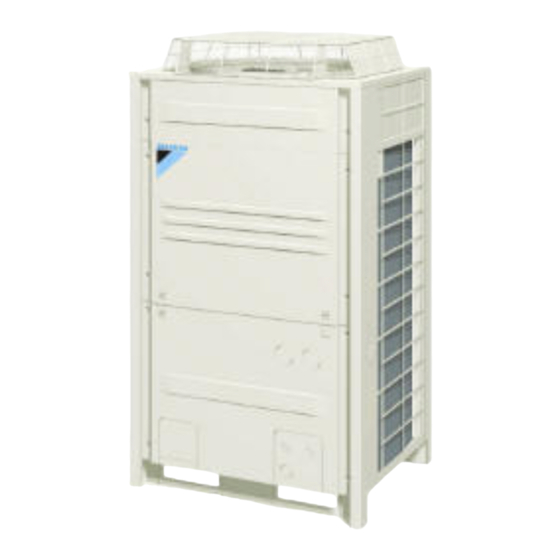
- Page 1 INSTALLATION MANUAL Inverter condensing unit ERX125A7W1B ERX200A7W1B ERX250A7W1B...
- Page 2 a ≥10 mm a ≥50 mm a ≥200 mm b ≥300 mm b ≥100 mm b ≥300 mm (mm) c ≥10 mm c ≥50 mm d ≥500 mm d ≥500 mm a ≥10 mm a ≥50 mm a ≥200 mm b ≥300 mm b ≥100 mm b ≥300 mm...
- Page 3 2PW40200-4B...
- Page 4 2PW40200-4B...
-
Page 5: Table Of Contents
3. Selecting installation site............2 OTHER DAMAGE TO THE EQUIPMENT. BE SURE ONLY 4. Inspecting and handling the unit ..........3 TO USE ACCESSORIES MADE BY DAIKIN WHICH ARE 5. Unpacking and placing the unit..........3 SPECIFICALLY DESIGNED FOR USE WITH THE 6. -
Page 6: Introduction
field supply and are to be selected by the installer. Refer to the manual "Option kit for combination of If not, the unit may fall over and cause damage or Daikin condensing units with field supplied evaporators" for injury. more details. -
Page 7: Inspecting And Handling The Unit
NSPECTING AND HANDLING THE UNIT The equipment described in this manual may cause electronic noise generated from radio-frequency At delivery, the package should be checked and any damage should energy. The equipment complies to specifications that be reported immediately to the carrier claims agent. are designed to provide reasonable protection against When handling the unit, take into account the following: such interference. -
Page 8: Refrigerant Piping
6.1. Installation tools Support the unit with a foundation of 67 mm wide or more. (The support leg of the unit is 67 mm wide, see figure Make sure to use installation tools (gauge manifold charge hose, Fasten the unit in place using four etc.) that are exclusively used for R410A installations to withstand the foundation bolts M12. -
Page 9: Connecting The Refrigerant Piping
6.4. Connecting the refrigerant piping Piping connections (See figure 9) Front connection or side connection Front connection: Installation of refrigerant piping is possible as front connection or Remove the stop valve cover to connect. side connection (when taken out from the bottom) as shown in Bottom connection: the figure. -
Page 10: Protection Against Contamination When Installing Pipes
4.2 How to calculate the additional refrigerant to be charged EAK TEST AND VACUUM DRYING Additional refrigerant to be charged R (kg) R should be rounded off in units of 0.1 kg The units were checked for leaks by the manufacturer. After connecting the field piping, perform the following inspections. -
Page 11: Field Wiring
8.1. Internal wiring – Parts table Vacuum drying: Use a vacuum pump which can evacuate to –100.7 kPa (5 Torr, –755 mm Hg) Refer to the wiring diagram sticker on the unit. The abbreviations Evacuate the system from the liquid and gas pipes by using a used are listed below: vacuum pump for more than 2 hours and bring the system to A1P~6P.... -
Page 12: Power Circuit And Cable Requirements
......Terminal NOTE Select the power supply cable in accordance with ......Protective earth (screw) relevant local and national regulations. BLK ......Black Wire size must comply with the applicable local BLU ......Blue and national code. BRN......Brown Specifications for local wiring power cord and branch wiring are in compliance with IEC60245. -
Page 13: System Examples
Make sure that all wiring is secure, the specified wires are used, Outside the unit, make sure the weak low voltage and no external forces act on the terminal connection or wires. electric wiring (i.e. for the remote control, between Improper connections or installation may result in fire. -
Page 14: Field Line Connection: Power Wiring
8.6. Field line connection: power wiring 8.7. Wiring example for wiring inside unit The power cord must be clamped to the plastic bracket using field figure supplied clamp material. Electric wiring The green and yellow striped wrapped wires must be used for Wiring between outdoor unit and control box grounding. -
Page 15: Checking Of Unit And Installation Conditions
10. C The filled out label must be adhered in the proximity of the product HECKING OF UNIT AND INSTALLATION charging port (e.g. onto the inside of the service cover). CONDITIONS factory refrigerant charge Be sure to check the following: of the product: see unit name plate The piping work... -
Page 16: Additional Refrigerant Charge
Remove the cap and turn the valve counterclockwise with the NOTE "11.3. Stop valve operation procedure" on hexagon wrench. page 11 for details on how to handle stop valves. Turn it until the shaft stops. The refrigerant charging port is connected to the Do not apply excessive force to the stop valve. - Page 17 Press the button once if the LEDs combination is not Complete BS1 MODE as in the figure below. If the display on the remote controller shows a flashing PE code, charging is almost finished. Wherever during this procedure, press the NOTE BS1 MODE When the unit stops operating, close valve A immediately and...
-
Page 18: Checks After Adding Refrigerant
12. B EFORE OPERATION Final adjustment of the amount of refrigerant When the unit displays an out of temperature range, the charging of refrigerant can not be completed. 12.1. Service precautions Out of outdoor temperature range H1P H2P H3P H4P H5P H6P H7P w c c c w x x WARNING: ELECTRIC SHOCK Complete the charging of refrigerant on another time when... -
Page 19: Checks Before Initial Start-Up
12.2. Checks before initial start-up Location of the DIP switches, LEDs and buttons Led H1~8P NOTE Remark that during the first running period of the unit, required power input may be higher than stated on the Push button switches BS1~BS5 nameplate of the unit. -
Page 20: Test Operation
12.4. Test operation Setting the mode The set mode can be changed with the button according BS1 MODE Do not insert fingers, rods or other objects into the air to the following procedure: inlet or outlet. When the fan is rotating at high speed, it will cause injury. - Page 21 Test operation procedure Correcting after abnormal completion of the test operation The test operation is only completed if there is no malfunction code Air handling units are not checked by the outdoor unit displayed on the remote controller. In case of a displayed malfunction during test operation.
-
Page 22: Service Mode Operation
13. S 14. C ERVICE MODE OPERATION AUTION FOR REFRIGERANT LEAKS Vacuuming method (Points to note in connection with refrigerant leaks.) At the first installation, this vacuuming is not required. It is required only for repair purposes. 14.1. Introduction When the unit is at standstill and under the setting mode 2, set The installer and system specialist shall secure safety against the required function B (refrigerant recovery operation/ leakage according to local regulations or standards. -
Page 23: Disposal Requirements
Calculate the smallest room volume (m OTES In a case such as the following, calculate the volume of (A), (B) as a single room or as the smallest room. Where there are no smaller room divisions Where there is a room division but there is an opening between the rooms sufficiently large to permit a free flow of air back and forth. - Page 24 NOTES NOTES...
- Page 25 NOTES...
- Page 26 4PW30064-1D...
Need help?
Do you have a question about the ERX125A7W1B and is the answer not in the manual?
Questions and answers