Daikin FDMQ-R Series Manual
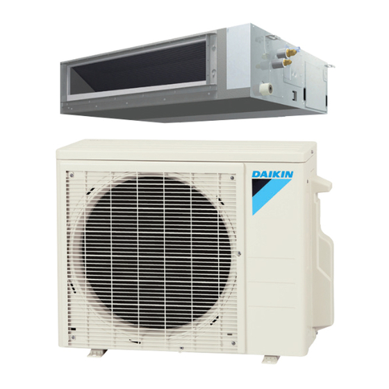
Inverter pair duct connected type
Hide thumbs
Also See for FDMQ-R Series:
- Service manual (146 pages) ,
- Manual (484 pages) ,
- Service manual (20 pages)

Related Manuals for Daikin FDMQ-R Series


Summary of Contents for Daikin FDMQ-R Series
- Page 1 SiUS071735EB Service Manual Inverter Pair Duct Connected Type FDMQ-R Series [Applied Models] Inverter Pair : Heat Pump...
- Page 2 SiUS071735EB Inverter Pair Duct Connected Type FDMQ-R Series Heat Pump Indoor Unit FDMQ09RVJU FDMQ12RVJU FDMQ15RVJU FDMQ18RVJU FDMQ24RVJU Outdoor Unit RX09RMVJU RX09RMVJU9 RX09RMVJU9A RX12RMVJU RX12RMVJU9 RX12RMVJU9A RX15RMVJU RX15RMVJUA RX18RMVJU RX18RMVJU9 RX18RMVJU9A RX24RMVJU RX24RMVJUA Table of Contents...
-
Page 3: Table Of Contents
SiUS071735EB 1. Safety Cautions................... v 1.1 Warnings and Cautions Regarding Safety of Workers......... v 1.2 Warnings and Cautions Regarding Safety of Users........vii 2. Icons Used ....................x Part 1 List of Functions ..............1 1. Functions.....................2 Part 2 Specifications ............... 3 1. - Page 4 SiUS071735EB 2.11 Electronic Expansion Valve Control ............41 2.12 Malfunctions ....................44 Part 5 Remote Controller ............... 45 1. Wired Remote Controller (BRC1E73) ............46 2. Wireless Remote Controller (BRC082A43)..........52 Part 6 Service Diagnosis..............54 1. General Problem Symptoms and Check Items .........56 2.
- Page 5 SiUS071735EB 4.28 Electrical Box Temperature Rise.............. 101 4.29 Radiation Fin Temperature Rise .............. 102 4.30 Output Overcurrent Detection ..............103 5. Check ......................105 5.1 Thermistor Resistance Check ..............105 5.2 Indoor Fan Motor Connector Check ............106 5.3 Power Supply Waveforms Check............. 106 5.4 Electronic Expansion Valve Check............
-
Page 6: Safety Cautions
Safety Cautions SiUS071735EB 1. Safety Cautions Be sure to read the following safety cautions before conducting repair work. After the repair work is complete, be sure to conduct a test operation to ensure that the equipment operates normally, and explain the cautions for operating the product to the customer. This manual is for the person in charge of maintenance and... - Page 7 SiUS071735EB Safety Cautions Warning Be sure to discharge the capacitor completely before conducting repair work. The step-up capacitor supplies high-voltage electricity to the electrical components of the outdoor unit. A charged capacitor may cause an electrical shock. Do not turn the air conditioner on or off by plugging in or unplugging the power cable.
-
Page 8: Warnings And Cautions Regarding Safety Of Users
Safety Cautions SiUS071735EB Caution Be sure to conduct repair work with appropriate tools. The use of inappropriate tools may cause injury. Be sure to check that the refrigerating cycle section has cooled down enough before conducting repair work. Working on the unit when the refrigerating cycle section is hot may cause burns. - Page 9 SiUS071735EB Safety Cautions Warning Be sure to use the specified cable for wiring between the indoor and outdoor units. Make the connections securely and route the cable properly so that there is no force pulling the cable at the connection terminals. Improper connections may cause excessive heat generation or fire.
- Page 10 Safety Cautions SiUS071735EB Caution Installation of a leakage breaker is necessary in some cases depending on the conditions of the installation site, to prevent electrical shocks. Do not install the equipment in a place where there is a possibility of combustible gas leaks.
-
Page 11: Icons Used
SiUS071735EB Icons Used 2. Icons Used The following icons are used to attract the attention of the reader to specific information. Icon Type of Description Information A Warning is used when there is danger of personal injury. Warning Warning Caution A Caution is used when there is danger that the reader, through incorrect manipulation, may damage equipment, lose data, get Caution... -
Page 12: Part 1 List Of Functions
SiUS071735EB Part 1 List of Functions 1. Functions.....................2 List of Functions... -
Page 13: Functions
SiUS071735EB Functions 1. Functions Category Functions Category Functions Basic Inverter (with inverter power control) Health & Auto cleaning filter — — Functions Cleanliness Operation limit for cooling Air-purifying filter — — Refer to P. 139 Operation limit for heating Titanium apatite deodorizing filter —... -
Page 14: Part 2 Specifications
SiUS071735EB Part 2 Specifications 1. Specifications ....................4 Specifications... -
Page 15: Specifications
SiUS071735EB Specifications 1. Specifications Indoor Unit FDMQ09RVJU FDMQ09RVJU Model RX09RMVJU RX09RMVJU9 Outdoor Unit Cooling Heating Cooling Heating Power Supply 1 phase, 208-230 V, 60 Hz 1 phase, 208-230 V, 60 Hz 2.64 — 2.64 — Cooling Capacity 1 4 Btu/h 9,000 —... - Page 16 Specifications SiUS071735EB Indoor Unit FDMQ09RVJU FDMQ12RVJU Model RX09RMVJU9A RX12RMVJU Outdoor Unit Cooling Heating Cooling Heating Power Supply 1 phase, 208-230 V, 60 Hz 1 phase, 208-230 V, 60 Hz 2.64 — 3.18 — Cooling Capacity 1 4 Btu/h 9,000 — 10,800 —...
- Page 17 SiUS071735EB Specifications Indoor Unit FDMQ12RVJU FDMQ12RVJU Model RX12RMVJU9 RX12RMVJU9A Outdoor Unit Cooling Heating Cooling Heating Power Supply 1 phase, 208-230 V, 60 Hz 1 phase, 208-230 V, 60 Hz 3.18 — 3.18 — Cooling Capacity 1 4 Btu/h 10,800 — 10,800 —...
- Page 18 Specifications SiUS071735EB Indoor Unit FDMQ15RVJU FDMQ18RVJU Model RX15RMVJU(A) RX18RMVJU Outdoor Unit Cooling Heating Cooling Heating Power Supply 1 phase, 208-230 V, 60 Hz 1 phase, 208-230 V, 60 Hz 4.23 — 5.16 — Cooling Capacity 1 4 Btu/h 14,400 — 17,600 —...
- Page 19 SiUS071735EB Specifications Indoor Unit FDMQ18RVJU FDMQ24RVJU Model RX18RMVJU9(A) RX24RMVJU(A) Outdoor Unit Cooling Heating Cooling Heating Power Supply 1 phase, 208-230 V, 60 Hz 1 phase, 208-230 V, 60 Hz 5.16 — 6.39 — Cooling Capacity 1 4 Btu/h 17,600 — 21,800 —...
-
Page 20: Part 3 Printed Circuit Board Connector Wiring Diagram
SiUS071735EB Part 3 Printed Circuit Board Connector Wiring Diagram 1. Indoor Unit....................10 1.1 FDMQ09/12/15/18/24RVJU ............... 10 2. Wired Remote Controller................12 2.1 BRC1E73 ....................12 3. Wireless Remote Controller Receiver ............13 3.1 BRC082A43 ....................13 4. Outdoor Unit....................14 4.1 RX09/12R....................14 4.2 RX15/18/24R.................... -
Page 21: Indoor Unit
SiUS071735EB Indoor Unit 1. Indoor Unit FDMQ09/12/15/18/24RVJU Control PCB X15A Connector for float switch (A1P) X16A Connector for room temperature thermistor (suction air thermistor) (R1T) X17A, X18A Connector for indoor heat exchanger thermistor (R2T, R3T) X25A Connector for drain pump motor X27A Connector for terminal block (for power supply) X28A... - Page 22 Indoor Unit SiUS071735EB Indoor Fan PCB Connector for control PCB (A1P) (A2P) Connector for reactor Connector for indoor fan motor X10A Connector for terminal block (for power supply) Fuse (5 A, 250 V) Fuse (6.3 A, 250 V) LED for service monitor (green) X10A 2P442228-16 2P442228-17...
-
Page 23: Wired Remote Controller
SiUS071735EB Wired Remote Controller 2. Wired Remote Controller BRC1E73 Wired Remote Controller PCB 1) P1, P2 Terminal for indoor unit 2) R1T Room temperature thermistor 2P298037-7 Printed Circuit Board Connector Wiring Diagram... -
Page 24: Wireless Remote Controller Receiver
Wireless Remote Controller Receiver SiUS071735EB 3. Wireless Remote Controller Receiver BRC082A43 Wireless Remote MAIN/SUB setting switch Controller PCB Refer to page 127 for details. Address setting switch Refer to page 127 for details. P1, P2 Terminal for indoor unit control PCB (A1P) 3P156152-1 Printed Circuit Board Connector Wiring Diagram... -
Page 25: Outdoor Unit
SiUS071735EB Outdoor Unit 4. Outdoor Unit RX09/12R Main PCB (PCB1) 1) S20 Connector for electronic expansion valve coil 2) S30 Connector for compressor 3) S40 Connector for overload protector (for RX09/12RMVJU(9)) / Connector for overload protector and high pressure switch (for RX09/12RMVJU9A) 4) S71 Connector for DC fan motor 5) S80... -
Page 26: Rx15/18/24R
Outdoor Unit SiUS071735EB RX15/18/24R Main PCB 1) S20 Connector for electronic expansion valve coil 2) S40 Connector for overload protector 3) S70 Connector for DC fan motor 4) S80 Connector for four way valve coil 5) S90 Connector for thermistors (outdoor temperature, outdoor heat exchanger, discharge pipe) 6) HL1, HN1, S Connector for terminal block... -
Page 27: Part 4 Functions And Control
SiUS071735EB Part 4 Functions and Control 1. Main Functions..................17 1.1 Temperature Control .................. 17 1.2 Frequency Principle..................17 1.3 Fan Speed Control for Indoor Unit ............. 19 1.4 Program Dry Operation ................20 1.5 Clock and Calendar Setting (With Wired Remote Controller BRC1E73) ... 21 1.6 Schedule TIMER Operation (With Wired Remote Controller BRC1E73) ... -
Page 28: Main Functions
Main Functions SiUS071735EB 1. Main Functions Temperature Control Definitions of The definitions of temperatures are classified as following. Temperatures Room temperature: temperature of lower part of the room Set temperature: temperature set by remote controller Room thermistor temperature: temperature detected by room temperature thermistor ... - Page 29 SiUS071735EB Main Functions The following drawing shows a schematic view of the inverter principle: Refrigerant circulation rate (high) high speed Amount of heat Amount of heat exchanged air (large) exchanged air (large) high f low f Amount of heat Amount of heat exchanged air (small) exchanged air (small) low speed...
-
Page 30: Fan Speed Control For Indoor Unit
Main Functions SiUS071735EB Fan Speed Control for Indoor Unit With Wired Remote Controller (BRC1E73) To change the fan speed, press Fan Speed button and select the fan speed from Low/Medium/High/Auto. Auto cannot be selected if the indoor unit does not have Auto Fan speed function. ... -
Page 31: Program Dry Operation
SiUS071735EB Main Functions Program Dry Operation Outline Program dry operation removes humidity while preventing the room temperature from lowering. Since the microcomputer controls both the temperature and airflow rate, the temperature adjustment and FAN setting buttons are inoperable. Details The microcomputer automatically sets the temperature and airflow rate. The difference between the room thermistor temperature at start-up and the target temperature is divided into two zones. -
Page 32: Clock And Calendar Setting (With Wired Remote Controller Brc1E73)
Main Functions SiUS071735EB Clock and Calendar Setting (With Wired Remote Controller BRC1E73) Press Menu/OK button to display the main menu screen. Press buttons to select Clock & Calendar on the main menu screen. Press Menu/OK button to display the clock & calendar screen. Press buttons to select Date &... - Page 33 SiUS071735EB Main Functions Select Hour with buttons. Change the hour with buttons. Holding down the button causes the number to change continuously. Select Minute with buttons. Change the minute with buttons. Holding down the button causes the number to change continuously. Press Menu/OK button.
-
Page 34: Schedule Timer Operation (With Wired Remote Controller Brc1E73)
Main Functions SiUS071735EB Schedule TIMER Operation (With Wired Remote Controller BRC1E73) Outline Day settings are selected from 4 patterns: 7 Days Weekday/Sat/Sun Weekday/Weekend Everyday Up to 5 actions can be set for each day. Details Set the startup time and operation stop time. Startup time, cooling and heating temperature setpoints can be configured. - Page 35 SiUS071735EB Main Functions Daily Patterns The schedule screen will appear. Press buttons to select Daily Patterns on the schedule screen. The daily patterns screen will appear when Menu/OK button is pressed. Press buttons to select 7 Days Weekday/Sat/Sun Weekday/Weekend Everyday the daily patterns screen.
- Page 36 Main Functions SiUS071735EB Press buttons to move the highlighted item and press buttons to configure ON/OFF/-- settings. --, ON, or OFF changes in sequence when buttons are pressed. ON: The temperature setpoints can be configured. OFF: The setback temperature setpoints can be configured.
-
Page 37: Drain Pump Control
SiUS071735EB Main Functions Enabling or disabling the schedule Display the schedule screen. Press buttons to select Enable / Disable on the schedule screen. Press Menu/OK button to display the enable/disable screen. Press buttons to select Enable Disable on the enable/disable screen. - Page 38 Main Functions SiUS071735EB 1.7.2 If the Float Switch is OFF with the Thermostat ON in Cooling Operation ∗2 ∗1 ∗4 ∗3 Float switch 5 sec. 5 sec. Thermostat (running) Error display Drain pump 5 min. 5 sec. 5 min. 5 sec. 5 min. 5 sec. (R24610) ...
-
Page 39: Hot Start Control (In Heating Operation Only)
SiUS071735EB Main Functions 1.7.4 If the Float Switch Turns OFF and ON Continuously, or the Float Switch Turns OFF While AF Displayed ∗1 ∗2 ∗3 Float Switch 5 sec. 5 sec. 5 sec. 5 sec. 5 sec. Thermostat (running) Error Display Drain Pump 5 min. -
Page 40: Other Functions
Main Functions SiUS071735EB Other Functions 1.9.1 Signal Receiving Sign When the indoor unit receives a signal from the remote controller, the unit emits a signal receiving sound. 1.9.2 Auto-restart Function If a power failure (even a momentary one) occurs during the operation, the system restarts automatically in the same conditions as before when the power supply is restored to the conditions prior to the power failure. -
Page 41: Control Specification
SiUS071735EB Control Specification 2. Control Specification Mode Hierarchy Outline The air conditioner control has normal operation mode, forced operation mode, and power transistor test mode for installation and servicing. Details Heat Pump Model Air conditioner control mode Forced operation mode Forced cooling operation (for pump down operation) Power transistor test mode Normal operation mode... -
Page 42: Frequency Control
Control Specification SiUS071735EB Frequency Control Outline The compressor frequency is determined according to the difference between the room thermistor temperature and the target temperature. When the shift of the frequency is less than zero (ΔF<0) by PI control, the target frequency is used as the command frequency. Dropping function Input current control, etc. - Page 43 SiUS071735EB Control Specification Initial Frequency When starting the compressor, the frequency is initialized according to the D value of the indoor unit. D signal: Indoor frequency command The difference between the room thermistor temperature and the target temperature is taken as the D value and is used for D signal of frequency command.
-
Page 44: Controls At Mode Changing/Start-Up
Control Specification SiUS071735EB Controls at Mode Changing/Start-up 2.3.1 Preheating Control Outline The inverter operation in open phase starts with the conditions of the outdoor temperature, the discharge pipe temperature, the radiation fin temperature and the preheating command from the indoor unit. Details Outdoor temperature ... - Page 45 SiUS071735EB Control Specification 2.3.3 Four Way Valve Operation Compensation Outline At the beginning of operation as the four way valve is switched, the pressure difference to activate the four way valve is acquired when the output frequency is higher than a certain fixed frequency, for a certain fixed time.
-
Page 46: Discharge Pipe Temperature Control
Control Specification SiUS071735EB Discharge Pipe Temperature Control Outline The discharge pipe temperature is used as the internal temperature of the compressor. If the discharge pipe temperature rises above a certain level, the upper limit of frequency is set to keep the discharge pipe temperature from rising further. -
Page 47: Input Current Control
SiUS071735EB Control Specification Input Current Control Outline The microcomputer calculates the input current while the compressor is running, and sets the frequency upper limit based on the input current. In case of heat pump models, this control is the upper limit control of frequency and takes priority over the lower limit control of four way valve operation compensation. -
Page 48: Freeze-Up Protection Control
Control Specification SiUS071735EB Freeze-up Protection Control Outline During cooling operation, the signal sent from the indoor unit determines the frequency upper limit and prevents the indoor heat exchanger from freezing. Details When the freeze-up protection control starts, the compressor stops, the airflow rate is fixed to L tap, and the drain pump turns ON. -
Page 49: Heating Peak-Cut Control
SiUS071735EB Control Specification Heating Peak-cut Control During heating operation, the indoor heat exchanger temperature determines the frequency upper limit to prevent abnormal high pressure. The operating frequency limitation is judged with the indoor heat exchanger temperature. Stop zone Dropping zone Keep zone Up zone Reset zone... -
Page 50: Outdoor Fan Control
Control Specification SiUS071735EB Outdoor Fan Control 1. Fan ON control to cool down the electrical box The outdoor fan is turned ON when the electrical box temperature is high while the compressor is OFF. 2. Fan OFF control during defrosting The outdoor fan is turned OFF during defrosting. -
Page 51: Defrost Control
SiUS071735EB Control Specification 2.10 Defrost Control Outline Defrosting is carried out by the cooling cycle (reverse cycle). The defrosting time or outdoor heat exchanger temperature must be more than a certain value to finish defrosting. Details Conditions for Starting Defrost ... -
Page 52: Electronic Expansion Valve Control
Control Specification SiUS071735EB 2.11 Electronic Expansion Valve Control Outline The following items are included in the electronic expansion valve control. Electronic expansion valve is fully closed 1. Electronic expansion valve is fully closed when turning on the power. 2. Pressure equalizing control Open Control 1. - Page 53 SiUS071735EB Control Specification 2.11.1 Initialization as Power Supply On The electronic expansion valve is initialized (fully closed) when the power is turned on. Then, the valve opening is set and the pressure is equalized. 2.11.2 Pressure Equalizing Control When the compressor is stopped, the pressure equalizing control is activated. The electronic expansion valve opens and the pressure is equalized.
- Page 54 Control Specification SiUS071735EB 2. When the operation mode is heating When the following condition is fulfilled, the discharge pipe thermistor disconnection is ascertained. Discharge pipe temperature +6°C (+10.8°F) < indoor heat exchanger temperature 09/12 class 15/18/24 class A (seconds) When the thermistor is disconnected When the disconnection is ascertained, the compressor continues operation for 9 minutes and then stops.
-
Page 55: Malfunctions
SiUS071735EB Control Specification 2.12 Malfunctions 2.12.1 Sensor Malfunction Detection Sensor malfunction can be detected in the following thermistor: 1. Outdoor heat exchanger thermistor 2. Discharge pipe thermistor 3. Radiation fin thermistor 4. Outdoor temperature thermistor 2.12.2 Detection of Overcurrent and Overload Outline An excessive output current is detected and the OL temperature is observed to protect the compressor. -
Page 56: Part 5 Remote Controller
SiUS071735EB Part 5 Remote Controller 1. Wired Remote Controller (BRC1E73) ............46 2. Wireless Remote Controller (BRC082A43)..........52 Remote Controller... -
Page 57: Wired Remote Controller (Brc1E73)
SiUS071735EB Wired Remote Controller (BRC1E73) 1. Wired Remote Controller (BRC1E73) 1. Operation mode selector button 11. LCD (with backlight) 4. Up button 5. Down button 6. Right button 7. Left button 9. Operation lamp 8. On/Off button 3. Menu/OK button 10. - Page 58 Wired Remote Controller (BRC1E73) SiUS071735EB 1. Operation mode selector button 7. Left button • Press this button to select the operation • Used to highlight the next items on the mode of your preference. left-hand side. • * Available modes vary with the indoor unit Each screen is scrolled in the left-hand model.
- Page 59 SiUS071735EB Wired Remote Controller (BRC1E73) Liquid Crystal Display • Three types of display mode (Standard, Detailed and Simple) are available. • Standard display is set by default. • Detailed and Simple displays can be selected in the main menu. Standard display 10.Changeover controlled 11.Setback by the master indoor unit...
- Page 60 Wired Remote Controller (BRC1E73) SiUS071735EB Simple display 1.Operation mode 14.Selectable Display Item 3.Setpoint 11.Setback 2.Fan speed 4.Stand by for Defrost/ <Simple display example> Hot start Note for all display modes • Depending on the field settings, while the indoor unit is stopped, OFF may be displayed instead of the operation mode and/or the setpoint may not be displayed.
- Page 61 SiUS071735EB Wired Remote Controller (BRC1E73) 1. Operation mode “Error: Push Menu button” “Warning: Push Menu button” Used to display the current operation • • Displayed if an error or warning is detected. mode: Cool, Heat, Vent, Fan, Dry or Auto. In Auto mode, the actual operation mode “Time to clean filter”...
- Page 62 Wired Remote Controller (BRC1E73) SiUS071735EB 11. Setback “ ” • The setback icon flashes when the unit is turned on by the setback control. 12. Airflow Direction “ ” Displayed when the airflow direction and • swing are set. If the connected indoor unit model does not •...
-
Page 63: Wireless Remote Controller (Brc082A43)
SiUS071735EB Wireless Remote Controller (BRC082A43) 2. Wireless Remote Controller (BRC082A43) ON OFF ON OFF TEMP TIME DOWN DOWN RESERVE CANCEL TIMER MODE TEST TEST TEST The situation which opened the front cover of the remote control (R25006) (R25007) Remote Controller... - Page 64 Wireless Remote Controller (BRC082A43) SiUS071735EB TIMER MODE START/STOP BUTTON DISPLAY “ ” “ I ” (SIGNAL TRANSMISSION) Use this button for TIMER MODE setting. This lights up when a signal is being transmitted. TIMER RESERVE/CANCEL BUTTON DISPLAY “ ” “ ”...
-
Page 65: Part 6 Service Diagnosis
SiUS071735EB Part 6 Service Diagnosis 1. General Problem Symptoms and Check Items .........56 2. Troubleshooting with LED .................57 2.1 Indoor Unit....................57 2.2 Outdoor Unit ....................57 3. Service Diagnosis ..................58 3.1 Wired Remote Controller (BRC1E73) ............58 3.2 Wireless Remote Controller (BRC082A43) ..........60 4. - Page 66 SiUS071735EB 5. Check ......................105 5.1 Thermistor Resistance Check ..............105 5.2 Indoor Fan Motor Connector Check ............106 5.3 Power Supply Waveforms Check............. 106 5.4 Electronic Expansion Valve Check............107 5.5 Four Way Valve Performance Check ............108 5.6 Inverter Unit Refrigerant System Check........... 108 5.7 Inverter Analyzer Check ................
-
Page 67: General Problem Symptoms And Check Items
SiUS071735EB General Problem Symptoms and Check Items 1. General Problem Symptoms and Check Items Symptom Check Item Details Reference Page The unit does not operate. Check the power supply. Check if the rated voltage is supplied. — Check the type of the indoor unit. Check if the indoor unit type is compatible with the —... -
Page 68: Troubleshooting With Led
Troubleshooting with LED SiUS071735EB 2. Troubleshooting with LED Indoor Unit Operation Lamp The operation lamp blinks when any of the following errors is detected. 1. When a protection device of the indoor or outdoor unit is activated, or when the thermistor malfunctions. -
Page 69: Service Diagnosis
SiUS071735EB Service Diagnosis 3. Service Diagnosis Wired Remote Controller (BRC1E73) Relations On power-up, the message “Checking the connection. Please standby.” will be displayed on the Between Modes remote controller screen temporarily and then the basic screen will be displayed. To access a mode from the basic screen, refer to the figure below. - Page 70 The error code will flash and the service Error Code: A1 Contact Info contact and model name or code may 0123-456-7890 be displayed. Indoor Model ---/000 Notify your Daikin dealer of the Error Outdoor Model ---/000 code and model name or code. Service Diagnosis...
-
Page 71: Wireless Remote Controller (Brc082A43)
SiUS071735EB Service Diagnosis Wireless Remote Controller (BRC082A43) Relations The following modes can be selected by using INSPECTION/TEST OPERATION button on the Between Modes remote controller. Service data can be obtained. Indoor unit settings can be made. Press INSPECTION/TEST Error code history ... - Page 72 Service Diagnosis SiUS071735EB Step Action Press UP or DOWN button and change the UNIT No. until the indoor unit starts to beep. UP button DOWN button (R15408) If you hear... Then... 3 short beeps Follow all steps below. 1 short beep Follow steps 3 and 4.
- Page 73 SiUS071735EB Service Diagnosis Step Action Press UP or DOWN button to change the error code upper digit until the indoor unit beeps. DOWN UP button DOWN button (R15411) If you hear... Then... 2 short beeps The upper digit matches. 1 short beep No digits match.
- Page 74 Service Diagnosis SiUS071735EB Step Action Press UP or DOWN button and change the error code lower digit until the indoor unit generates long beep. DOWN UP button DOWN button (R15413) If you hear... Then... 2 short beeps No digits match. 1 long beep Both upper and lower digits match.
-
Page 75: Troubleshooting
SiUS071735EB Troubleshooting 4. Troubleshooting Error Codes and Description Reference Error Codes Description Page System 00 Normal — Refrigerant shortage — Low-voltage detection or over-voltage detection Signal transmission error (between indoor unit and outdoor unit) Mismatching of indoor unit and outdoor unit Indoor Indoor unit PCB abnormality Unit... -
Page 76: Indoor Unit Pcb Abnormality
Troubleshooting SiUS071735EB Indoor Unit PCB Abnormality Error Code Method of Error The system checks the data from EEPROM. Detection Error Decision The data from the EEPROM is not received correctly. Conditions EEPROM (Electrically Erasable Programmable Read Only Memory): A memory chip that holds its content without power. -
Page 77: Drain Level Control System Abnormality
SiUS071735EB Troubleshooting Drain Level Control System Abnormality Error Code Method of Error The float switch detects error. Detection Error Decision The water level reaches its upper limit and the float switch turns OFF. Conditions Supposed Defective drain pump Causes ... -
Page 78: Indoor Fan Motor (Dc Motor) Or Related Abnormality
Troubleshooting SiUS071735EB Indoor Fan Motor (DC Motor) or Related Abnormality Error Code Method of Error Detection from the current flow on the fan PCB Detection Detection from the rotation speed of the fan motor in operation Error Decision The rotation speed is less than a certain level for 6 seconds. - Page 79 SiUS071735EB Troubleshooting The HAP lamp on the indoor unit control PCB is blinking while the HAP lamp on the fan PCB is not blinking. Turn OFF the power supply Turn OFF the power supply and wait for 10 minutes. and wait for 10 minutes. Check No.02 Check the fan motor connectors.
-
Page 80: Indoor Fan Pcb Abnormality
Troubleshooting SiUS071735EB Indoor Fan PCB Abnormality Error Code Method of Error Microcomputer checks the voltage state of the fan PCB. Detection Error Decision Overvoltage or voltage drop is detected on the fan PCB. Conditions Supposed Defective fan PCB Causes ... -
Page 81: Humidifier Or Related Abnormality
SiUS071735EB Troubleshooting Humidifier or Related Abnormality Error Code Method of Error Water leakage from humidifier(s) is detected based on the float switch ON/OFF changeover while Detection the system is not operating. Error Decision The float switch changes from ON to OFF while the system is OFF. Conditions Supposed ... -
Page 82: Thermistor Or Related Abnormality
Troubleshooting SiUS071735EB Thermistor or Related Abnormality C4, C5, C9 Error Code Method of Error The temperatures detected by the thermistors determine thermistor errors. Detection Error Decision The thermistor is disconnected or shorted while the unit is running. Conditions Supposed Disconnection of connector Causes ... -
Page 83: Remote Controller Thermistor Abnormality
SiUS071735EB Troubleshooting Remote Controller Thermistor Abnormality Error Code Method of Error Even if remote controller thermistor is faulty, system is possible to operate by system thermistor. Detection Malfunction detection is carried out by the temperature detected by the remote controller thermistor. -
Page 84: Signal Transmission Error (Between Indoor Unit And Remote Controller)
Troubleshooting SiUS071735EB Signal Transmission Error (Between Indoor Unit and Remote Controller) Error Code Method of Error In case of controlling 1 indoor unit with 2 remote controllers, check the system using microcomputer Detection if signal transmission between indoor unit and remote controller (main and sub) is normal. Error Decision Normal transmission does not continue for specified period. -
Page 85: Signal Transmission Error (Between Main Remote Controller And Sub Remote Controller)
SiUS071735EB Troubleshooting 4.10 Signal Transmission Error (Between MAIN Remote Controller and SUB Remote Controller) Error Code Method of Error In case of controlling 1 indoor unit with 2 remote controllers, check the system using microcomputer Detection if signal transmission between MAIN remote controller and SUB remote controller is normal. Error Decision Normal transmission does not continue for specified period. -
Page 86: Low-Voltage Detection Or Over-Voltage Detection
Troubleshooting SiUS071735EB 4.11 Low-voltage Detection or Over-voltage Detection Error Code Method of Error Low-voltage detection: Detection An abnormal voltage drop is detected by the DC voltage detection circuit. Over-voltage detection: An abnormal voltage rise is detected by the over-voltage detection circuit. Error Decision Low-voltage detection: Conditions... - Page 87 SiUS071735EB Troubleshooting Troubleshooting Be sure to turn off the power switch before connecting or disconnecting Caution connectors, or parts may be damaged. Check the power supply voltage. Is the voltage fluctuation Correct the power supply. within ±10% from the rated value? Check the connection of the compressor harness.
-
Page 88: Signal Transmission Error (Between Indoor Unit And Outdoor Unit)
Troubleshooting SiUS071735EB 4.12 Signal Transmission Error (Between Indoor Unit and Outdoor Unit) Error Code Method of Error The signal transmission data from the outdoor unit is checked whether it is normal. Detection Error Decision The data sent from the outdoor unit cannot be received normally, or the content of the data is Conditions abnormal. - Page 89 SiUS071735EB Troubleshooting Troubleshooting Be sure to turn off the power switch before connecting or disconnecting Caution connectors, or parts may be damaged. Check No.11 Check the power supply voltage. Refer to P.106 Is the voltage fluctuation Correct the power supply. within ±10% from the rated value? Check the connection wires...
-
Page 90: Mismatching Of Indoor Unit And Outdoor Unit
Troubleshooting SiUS071735EB 4.13 Mismatching of Indoor Unit and Outdoor Unit Error Code Error Decision Improper combination of indoor and outdoor units Conditions Supposed Defective indoor unit PCB Causes Indoor-outdoor unit transmission wiring error Defective optional unit(s) wirings ... -
Page 91: Outdoor Unit Pcb Abnormality
SiUS071735EB Troubleshooting 4.14 Outdoor Unit PCB Abnormality Error Code Method of Error The system checks if the microprocessor is working in order. Detection The system checks if the zero-cross signal comes in properly. Error Decision The microprocessor program runs out of control. Conditions ... -
Page 92: Ol Activation (Compressor Overload)
Troubleshooting SiUS071735EB 4.15 OL Activation (Compressor Overload) Applicable RX09/12/15/18/24RMVJU, RX09/12/18RMVJU9, RX15/24RMVJUA, RX18RMVJU9A Models Error Code Method of Error A compressor overload is detected through compressor OL. Detection Error Decision If the error repeats, the system is shut down. Conditions ... - Page 93 SiUS071735EB Troubleshooting Troubleshooting Be sure to turn off the power switch before connecting or disconnecting Caution connectors, or parts may be damaged. Check No.01 Refer to P.105 Discharge pipe thermistor Insert the thermistor in disconnected? position. Check No.12 Refer to P.107 Check No.
-
Page 94: Ol Activation (Compressor Overload) Or Hps Activation (High Pressure Switch)
Troubleshooting SiUS071735EB 4.16 OL Activation (Compressor Overload) or HPS Activation (High Pressure Switch) Applicable RX09/12RMVJU9A Models Error Code Method of Error A compressor overload is detected through compressor OL. Detection Abnormality is detected when the contact of the high pressure switch opens. Error Decision ... - Page 95 SiUS071735EB Troubleshooting Troubleshooting Be sure to turn off the power switch before connecting or disconnecting Caution connectors, or parts may be damaged. Check No.01 Refer to P.105 Thermistor Insert the thermistor in disconnected? ∗ Discharge pipe thermistor position. ∗ Indoor heat exchanger thermistor ∗...
- Page 96 Troubleshooting SiUS071735EB Note: OL (Q1L) activating temperature: 130°C (266°F) OL (Q1L) recovery temperature: 95°C (203°F) High pressure switch (S1PH) activating pressure: 602 psi (4.15 MPa) High pressure switch (S1PH) recovery pressure: 464 psi (3.2 MPa) Note: When replacing the defective thermistor(s), replace the thermistors as ASSY. Service Diagnosis...
-
Page 97: Compressor Lock
SiUS071735EB Troubleshooting 4.17 Compressor Lock Error Code Method of Error A compressor lock is detected by the current waveform generated when applying high-frequency Detection voltage to the motor. Error Decision If the error repeats, the system is shut down. Conditions ... -
Page 98: Dc Fan Lock (Outdoor Fan Motor)
Troubleshooting SiUS071735EB 4.18 DC Fan Lock (Outdoor Fan Motor) Error Code Method of Error An error is determined with the high-voltage fan motor rotation speed detected by the Hall IC. Detection Error Decision The fan does not start in 15 ~ 30 seconds even when the fan motor is running. Conditions ... -
Page 99: Input Overcurrent Detection
SiUS071735EB Troubleshooting 4.19 Input Overcurrent Detection Error Code Method of Error An input overcurrent is detected by checking the input current value with the compressor running. Detection Error Decision The current exceeds about 12.0 ~ 18.0 A (depending on the model) for 2.5 seconds with the Conditions compressor running. -
Page 100: Four Way Valve Abnormality
Troubleshooting SiUS071735EB 4.20 Four Way Valve Abnormality Error Code Method of Error The room temperature thermistor and the indoor heat exchanger thermistor are checked if they Detection function within their normal ranges in each operation mode. Error Decision The following condition continues over 10 minutes after operating for 5 minutes. Conditions ... - Page 101 SiUS071735EB Troubleshooting Troubleshooting Be sure to turn off the power switch before connecting or disconnecting Caution connectors, or parts may be damaged. Check No.01 Four way valve coil Refer to P.105 Correct the four way valve disconnected (loose)? coil. Check No.13 Refer to P.108 Harness disconnected? Reconnect the harness.
-
Page 102: Discharge Pipe Temperature Control
Troubleshooting SiUS071735EB 4.21 Discharge Pipe Temperature Control Error Code Method of Error An error is determined with the temperature detected by the discharge pipe thermistor. Detection Error Decision If the temperature detected by the discharge pipe thermistor rises above A, the compressor Conditions stops. -
Page 103: High Pressure Control In Cooling
SiUS071735EB Troubleshooting 4.22 High Pressure Control in Cooling Error Code Method of Error High-pressure control (operation halt, frequency drop, etc.) is activated in cooling operation if the Detection temperature sensed by the outdoor heat exchanger thermistor exceeds the limit. Error Decision The temperature sensed by the outdoor heat exchanger thermistor rise above 57.5 ~ 61°C Conditions (135.5 ~ 141.8°F) (depending on the model). - Page 104 Troubleshooting SiUS071735EB Troubleshooting Be sure to turn off the power switch before connecting or disconnecting Caution connectors, or parts may be damaged. Check No.01 Check the installation space. Refer to P.105 Check No. 17 Check No.12 Change the installation Check the installation Refer to P.107 location or direction.
-
Page 105: System Shutdown Due To Temperature Abnormality In Compressor
SiUS071735EB Troubleshooting 4.23 System Shutdown due to Temperature Abnormality in Compressor Error Code Method of Error Operation is halted when the temperature detected by the discharge pipe thermistor exceeds the Detection determined limit. Error Decision Temperature exceeds the detection threshold of 127.5°C (261.5°F) during forced cooling operation. Conditions Supposed ... -
Page 106: Compressor System Sensor Abnormality
Troubleshooting SiUS071735EB 4.24 Compressor System Sensor Abnormality Error Code Method of Error The system checks the DC current before the compressor starts. Detection Error Decision The voltage converted from the DC current before compressor start-up is out of the range 0.5 ~ Conditions 4.5 V. -
Page 107: Position Sensor Abnormality
SiUS071735EB Troubleshooting 4.25 Position Sensor Abnormality Error Code Method of Error A compressor start-up failure is detected by checking the compressor running condition through the Detection position detection circuit. Error Decision If the error repeats, the system is shut down. Conditions ... - Page 108 Troubleshooting SiUS071735EB Troubleshooting Be sure to turn off the power switch before connecting or disconnecting Caution connectors, or parts may be damaged. Check No.15 Turn off the power. Refer to P.109 Check the power supply voltage. Check No.18 Refer to P.112 Is the power supply voltage fluctuation within...
-
Page 109: Dc Voltage/Current Sensor Abnormality
SiUS071735EB Troubleshooting 4.26 DC Voltage/Current Sensor Abnormality Error Code Method of Error DC voltage or DC current sensor abnormality is identified based on the compressor running Detection frequency and the input current. Error Decision If the error repeats, the system is shut down. Conditions ... -
Page 110: Thermistor Or Related Abnormality (Outdoor Unit)
Troubleshooting SiUS071735EB 4.27 Thermistor or Related Abnormality (Outdoor Unit) H9, J3, J6, P4 Error Code Method of Error This fault is identified based on the thermistor input voltage to the microcomputer. Detection A thermistor fault is identified based on the temperature sensed by each thermistor. Error Decision ... - Page 111 SiUS071735EB Troubleshooting Troubleshooting In case of H9, J3, J6 Be sure to turn off the power switch before connecting or disconnecting Caution connectors, or parts may be damaged. Check No.01 Turn on the power again. Refer to P.105 Error displayed Reconnect the connectors again on remote or thermistors.
-
Page 112: Electrical Box Temperature Rise
Troubleshooting SiUS071735EB 4.28 Electrical Box Temperature Rise Error Code Method of Error An electrical box temperature rise is detected by checking the radiation fin thermistor with the Detection compressor off. Error Decision With the compressor off, the radiation fin temperature is above A. Conditions ... -
Page 113: Radiation Fin Temperature Rise
SiUS071735EB Troubleshooting 4.29 Radiation Fin Temperature Rise Error Code Method of Error A radiation fin temperature rise is detected by checking the radiation fin thermistor with the compressor on. Detection Error Decision If the radiation fin temperature with the compressor on is above A. Conditions ... -
Page 114: Output Overcurrent Detection
Troubleshooting SiUS071735EB 4.30 Output Overcurrent Detection Error Code Method of Error An output overcurrent is detected by checking the current that flows in the inverter DC section. Detection Error Decision A position signal error occurs while the compressor is running. Conditions ... - Page 115 SiUS071735EB Troubleshooting Troubleshooting Be sure to turn off the power switch before connecting or disconnecting Caution connectors, or parts may be damaged. ∗ An output overcurrent may result from wrong internal wiring. If the system is interrupted by an output Check No.15 overcurrent after the wires have been disconnected and reconnected for part replacement, check the Refer to P.109...
-
Page 116: Check
Check SiUS071735EB 5. Check Thermistor Resistance Check Check No.01 Disconnect the connectors of the thermistors from the PCB, and measure the resistance of each thermistor using a multimeter. The data is for reference purpose only. Thermistor temperature Resistance (k) °C °F –20 –4... -
Page 117: Indoor Fan Motor Connector Check
SiUS071735EB Check Indoor Fan Motor Connector Check Check No.02 1. Turn the power supply OFF. 2. With the fan motor connector disconnected, measure the resistance between each pin, then make sure that the resistance is more than the value mentioned in the following table. Measuring points Judgement White - Blue... -
Page 118: Electronic Expansion Valve Check
Check SiUS071735EB Electronic Expansion Valve Check Check No.12 Conduct the following to check the electronic expansion valve (EV). 1. Check if the EV connector is correctly connected to the PCB. 2. Turn the power off and on again, and check if the EV generates a latching sound. 3. -
Page 119: Four Way Valve Performance Check
SiUS071735EB Check Four Way Valve Performance Check Check No.13 Turn the power off and then on again. ∗ Four way valve coil Start heating operation. Cooling / Dry / Defrost: Not energized Heating: energized voltage at 208 - 230 Replace the outdoor unit VAC with compressor PCB (main PCB). -
Page 120: Inverter Analyzer Check
Check SiUS071735EB Inverter Analyzer Check Check No.15 Characteristics Inverter analyzer: RSUK0917C If an abnormal stop occurs due to compressor startup failure or overcurrent output when using an inverter unit, it is difficult to judge whether the stop is caused by the compressor failure or some other failure (main PCB, power module, etc.). - Page 121 SiUS071735EB Check Step 3 Activate power transistor test operation from the outdoor unit. Start method of power transistor test operation Note: Power transistor test operation can be activated only once after turning on the power supply. If reactivation of the power supply transistor operation is needed, turn the power supply off and then on again.
-
Page 122: Outdoor Fan Motor Check
Check SiUS071735EB Caution 1. When the output frequency is low, the LEDs blink slowly. As the output frequency increases, the LEDs blink quicker. (The LEDs look like they are lit.) 2. On completion of the inverter analyzer diagnosis, be sure to re-crimp the FASTON terminals. Otherwise, the terminals may be burned due to loosening. -
Page 123: Installation Condition Check
SiUS071735EB Check Installation Condition Check Check No.17 Installation condition check Check the allowable dimensions of the air Change the installation suction and location or direction. discharge area. Is the discharged air Change the installation short-circuited? location or direction. Is the outdoor heat Clean the outdoor heat exchanger very dirty? exchanger. -
Page 124: Outdoor Fan System Check
Check SiUS071735EB 5.11 Outdoor Fan System Check Check No.19 DC motor Check the outdoor fan system. Fan motor Is the lead wire connector outdoor fan running? Go to Check No. 16. disconnected? Reconnect the connector. Outdoor fan system is functioning. (R21195) 5.12 Main Circuit Short Check Check No.20... - Page 125 SiUS071735EB Check 15/18/24 class Multimeter (R25105) Service Diagnosis...
-
Page 126: Power Module Check
Check SiUS071735EB 5.13 Power Module Check Check No.22 Check to make sure that the voltage between (+) and (–) of the power module is approximately 0 V before checking. Disconnect the compressor harness connector from the outdoor unit PCB. To disengage the connector, press the protrusion on the connector. - Page 127 SiUS071735EB Check 15/18/24 class DC_P1: + (R20704) DC_N1: – Service Diagnosis...
-
Page 128: Part 7 Trial Operation And Field Settings
SiUS071735EB Part 7 Trial Operation and Field Settings 1. Pump Down Operation................118 2. Forced Cooling Operation ...............119 3. Trial Operation ..................120 4. Field Settings ..................123 4.1 How to Change the Field Settings............123 4.2 Overview of the Field Settings..............126 4.3 MAIN/SUB and Address Setting for Wireless Remote Controller .... -
Page 129: Pump Down Operation
SiUS071735EB Pump Down Operation 1. Pump Down Operation Outline In order to protect the environment, be sure to pump down when relocating or disposing of the unit. Details 1. Remove the valve cap from the liquid stop valve and the gas stop valve. 2. -
Page 130: Forced Cooling Operation
Forced Cooling Operation SiUS071735EB 2. Forced Cooling Operation Outline The forced cooling operation is allowed when both the following conditions are met. 1. The outdoor unit is not abnormal and not in the 3-minute standby mode. 2. The outdoor unit is not operating. Protection functions have priority over all other functions during forced cooling operation. -
Page 131: Trial Operation
SiUS071735EB Trial Operation 3. Trial Operation Outline Trial operation should be carried out in either cooling or heating operation. 1. Measure the supply voltage and make sure that it is within the specified range. 2. In COOL operation, select the lowest programmable temperature; in HEAT operation, select the highest programmable temperature. - Page 132 Trial Operation SiUS071735EB With Wired Remote Controller (BRC1E73) 1. Set to COOL or HEAT operation using the Basic screen remote controller. Cool Set to 2. Press and hold Cancel button for 4 seconds Press and hold Cancel or longer. Service settings menu is button for 4 seconds or displayed.
- Page 133 SiUS071735EB Trial Operation With Wireless Remote Controller (BRC082A43) 1. Press button and select the COOL or HEAT operation. button twice. “TEST” is displayed. 2. Press 3. Press button within 10 seconds, and the test operation starts. Monitor the operation of the indoor unit for a minimum of 10 minutes. During test operation, the indoor unit will continue to cool/heat regardless of the temperature setpoint and room temperature.
-
Page 134: Field Settings
Field Settings SiUS071735EB 4. Field Settings How to Change the Field Settings Outline If optional accessories are mounted on the indoor unit, the indoor unit setting may have to be changed. Refer to the instruction manual for each optional accessory. Note: When using 2 remote controllers for 1 indoor unit, change the field settings from MAIN remote controller. - Page 135 SiUS071735EB Field Settings 3. Highlight the mode, and select desired “Mode No.” by using (Up/Down) button. 20 22 4. In the case of setting per indoor unit during group control (When Mode No. such as 23 25 are selected), highlight the unit No. and select “Indoor unit No.” to be set by using ...
- Page 136 Field Settings SiUS071735EB Wireless Remote Controller (BRC082A43) UP button Mode No. DOWN button Field setting mode First code No. RESERVE button MODE button Second code No. INSPECTION/TEST button (R25096) To set the field settings, you have to change: Mode No. ...
-
Page 137: Overview Of The Field Settings
SiUS071735EB Field Settings Overview of the Field Settings : Factory setting First Second Code No. Mode Code Description of setting Filter cleaning Approx. Approx. Longlife sign interval 2,500 1,250 — — — — filter (used to change hrs. hrs. filter cleaning display interval Standard Approx. -
Page 138: Main/Sub And Address Setting For Wireless Remote Controller
Field Settings SiUS071735EB MAIN/SUB and Address Setting for Wireless Remote Controller Outline If setting multiple wireless remote controllers to operate in one room, perform address setting for the receiver and the wireless remote controller. If using both a wired remote controller and a wireless remote controller with 1 indoor unit, change the MAIN/SUB switch of the signal receiver PCB. - Page 139 SiUS071735EB Field Settings Wireless Remote Factory set is 1. Change the wireless remote controller address setting by the following steps, if Controller necessary. Address 1. Hold down button and /TEST button at the same time for at least 4 seconds to enter the field setting mode.
-
Page 140: Facility Setting (Cooling At Low Outdoor Temperature)
Field Settings SiUS071735EB After Setting Stick the Unit No. label on the receiver and the back of the wireless remote controller. Unit No. label (5) Wireless remote controller (2) (R25081) Note: Set the Unit No. of the receiver and the wireless remote controller to be the equal. If the settings differ, the signal from the remote controller cannot be transmitted. -
Page 141: Silicone Grease On Power Transistor/Diode Bridge
SiUS071735EB Silicone Grease on Power Transistor/Diode Bridge 5. Silicone Grease on Power Transistor/Diode Bridge Outline Apply the specified silicone grease to the heat radiation part of a power transistor/diode bridge when you replace an outdoor unit PCB. The silicone grease encourages the heat radiation of a power transistor/diode bridge. -
Page 142: Part 8 Appendix
SiUS071735EB Part 8 Appendix 1. Piping Diagrams..................132 1.1 Indoor Unit....................132 1.2 Outdoor Unit ..................... 133 2. Wiring Diagrams..................135 2.1 Indoor Unit....................135 2.2 Outdoor Unit ..................... 136 3. Operation Limit..................139 Appendix... -
Page 143: Piping Diagrams
SiUS071735EB Piping Diagrams 1. Piping Diagrams Indoor Unit FDMQ09/12/15/18/24RVJU C: 4D112974A Appendix... -
Page 144: Outdoor Unit
Piping Diagrams SiUS071735EB Outdoor Unit RX09/12RMVJU, RX09/12RMVJU9 OUTDOOR UNIT OUTDOOR TEMPERATURE HEAT EXCHANGER THERMISTOR 9/32 CuT 9/32 CuT HEAT EXCHANGER THERMISTOR 3/16 CuT 1/4 CuT 1/4 CuT 3/16 CuT MUFFLER WITH MOTOR FILTER OPERATED PROPELLER FAN VALVE MUFFLER WITH 3/8 CuT FILTER FOUR WAY VALVE... - Page 145 SiUS071735EB Piping Diagrams RX15/18RMVJU, RX15RMVJUA, RX18RMVJU9, RX18RMVJU9A OUTDOOR UNIT HEAT EXCHANGER OUTDOOR AIR 9/32 CuT THERMISTOR 9/32 CuT 9/32 CuT 9/32 CuT CAPILLARY TUBE 1 5/32 CuT 1/4 CuT 1/4 CuT CAPILLARY TUBE 2 REFRIGERANT FLOW 5/32 CuT COOLING MUFFLER HEATING WITH HEAT EXCHANGER...
-
Page 146: Wiring Diagrams
Wiring Diagrams SiUS071735EB 2. Wiring Diagrams Indoor Unit FDMQ09/12/15/18/24RVJU 3D112629A Note: A1P: Control PCB A2P: Indoor fan PCB Refer to Part 3 for Printed Circuit Board Connector Wiring Diagram. Appendix... -
Page 147: Outdoor Unit
SiUS071735EB Wiring Diagrams Outdoor Unit RX09/12RMVJU, RX09/12RMVJU9 WIRING DIAGRAM IPM1 MRM10 L2 2 C400 indoor C405 V150 3.15A 3.15A POWER SUPPLY MRCW FIELD WIRING. outdoor PCB1 NOTE 1. REFER TO THE NAMEPLATE FOR THE POWER t˚ t˚ t˚ IN CASE OF REQUIREMENTS. - Page 148 Wiring Diagrams SiUS071735EB RX09/12RMVJU9A 3D134904 Note: PCB1: Main PCB Refer to Part 3 for Printed Circuit Board Connector Wiring Diagram. Appendix...
- Page 149 SiUS071735EB Wiring Diagrams RX15/18/24RMVJU, RX15/24RMVJUA, RX18RMVJU9, RX18RMVJU9A WIRING DIAGRAM FIELD WIRING INDOOR MRM20 IPM1 TO INDOOR UNIT MRM10 L2 2 3.15A 3.15A W V U POWER SUPPLY MRCW X11A OUTDOOR NOTE 1. REFER TO THE NAMEPLATE FOR THE POWER REQUIREMENTS. t˚...
-
Page 150: Operation Limit
Operation Limit SiUS071735EB 3. Operation Limit RX09/12/15/18/24RMVJU, RX09/12/18RMVJU9, RX09/12/18RMVJU9A, RX15/24RMVJUA Heating Cooling 64.4 114.8 *NOTE 2 57.2 68 73.4 82.4 Indoor temp. (˚FWB) Indoor temp. (˚FDB) Notes: 1. The graphs are based on the following conditions. • Equivalent piping length 25ft •... - Page 151 Revision History Month / Year Version Revised contents 01 / 2018 SiUS071735E First edition 06 / 2020 SiUS071735EA Model addition: RX09/12RMVJU9, RX15/24RMVJUA, RX18RMVJU9(A) 09 / 2021 SiUS071735EB Model addition: RX09/12RMVJU9A...
- Page 152 Improper installation can result in water or refrigerant leakage, electrical shock, fire or explosion. Use only those parts and accessories supplied or specified by Daikin. Ask a qualified installer or contractor to install those parts and accessories. Use of unauthorized parts and accessories or improper installation of parts and accessories can result in water or refrigerant leakage, electrical shock, fire or explosion.
Need help?
Do you have a question about the FDMQ-R Series and is the answer not in the manual?
Questions and answers