Table of Contents
Advertisement
Quick Links
Advertisement
Table of Contents

Related Manuals for Symbol PDT 1100


Summary of Contents for Symbol PDT 1100
- Page 1 PDT 1100 Terminal Product Reference Guide...
- Page 3 PDT 1100 Terminal Product Reference Guide 70-35864-03 Revision A — December 2002 Symbol Technologies, Inc. One Symbol Plaza, Holtsville N.Y. 11742-1300...
- Page 5 PDT 1100 Terminal Product Reference Guide 70-35864-03 Revision A December 2002...
- Page 6 The software is provided strictly on an “as is” basis. All software, including firmware, furnished to the user is on a licensed basis. Symbol grants to the user a non-transferable and non-exclusive license to use each software or firmware program delivered hereunder (licensed program).
-
Page 7: Table Of Contents
Functions of the PDT 1100 Keys ........ - Page 8 PDT 1100 Terminal Product Reference Guide Selecting Tasks ............2-2 Entering Alphabetic Characters .
- Page 9 Recharging the Battery in the PDT 1100 ........
- Page 10 PDT 1100 Terminal Product Reference Guide Interface Specifications ........... . .A-11 CRG 1100 4-Slot Battery Charger Specifications .
-
Page 11: About This Guide
About This Guide The PDT 1100 Product Reference Guide provides instructions for setting up, initializing, operating, and maintaining the PDT 1100 Terminal, the CRD 1100 communications cradles, and the CRG 1100 4-slot battery charger. Chapter Descriptions The following topics are included in this guide: •... -
Page 12: Notational Conventions
PDT 1100 Terminal Product Reference Guide Notational Conventions The following conventions are used in this document: Italics are used to highlight specific items in the general text, and to identify chapters and sections in this and related documents. Bullets (•) indicate:... -
Page 13: Symbol Support Center
Call the Support Center from a phone near the scanning equipment so that the service person can try to talk you through your problem. If the equipment is found to be working properly and the problem is symbol readability, the Support Center will request samples of your bar codes for analysis at our plant. - Page 14 PDT 1100 Terminal Product Reference Guide Australia Austria/Österreich Symbol Technologies Pty. Ltd. Symbol Technologies Austria GmbH 432 St. Kilda Road Prinz-Eugen Strasse 70 / 2.Haus Melbourne, Victoria 3004 1040 Vienna, Austria 1-800-672-906 (Inside Australia) 01-5055794-0 (Inside Austria) +61-3-9866-6044 (Outside Australia)
- Page 15 Symbol Technologies Norway Postbus 24 7050 AA Hoybratenveien 35 C Varsseveld, Netherlands N-1055 OSLO, Norway 315-271700 (Inside Netherlands) +31-315-271700 (Outside Netherlands) Symbol’s repair depot and shipping address: Symbol Technologies Norway Enebakkveien 123 N-0680 OSLO, Norway +47 2232 4375 South Africa Spain/España Symbol Technologies Africa Inc.
- Page 16 Switchboard: 08 445 29 00 (domestic) Call Center: +46 8 445 29 29 (international) Support E-Mail: Sweden.Support@se.symbol.com If you purchased your Symbol product from a Symbol Business Partner, contact that Business Partner for service. For the latest version of this guide go to:http://www.symbol.com/manuals.
-
Page 17: Chapter 1. Getting Started
Chapter 1 Getting Started Introduction The PDT 1100 is a lightweight, battery-powered, hand-held laser bar code scanning terminal. The terminal is available in memory configurations of 2 MB and 512 K. The terminal can communicate in the following ways: •... -
Page 18: Parts Of The Pdt 1100
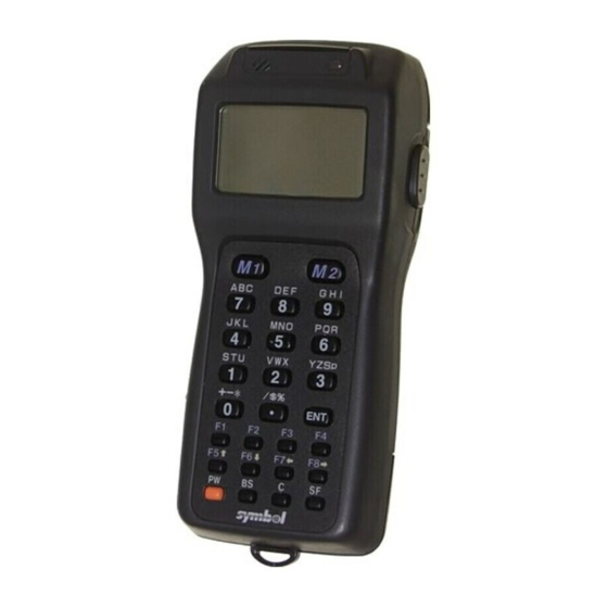
PDT 1100 Terminal Product Reference Guide Parts of the PDT 1100 Parts of the PDT 1100 terminal are illustrated in Figure 1.1. Refer to Table 1-1 Table 1- for a description of these parts. Decode LED Keypad Hand Strap Connector 35864018.eps... - Page 19 Getting Started Table 1-1. Main Parts of the PDT 1100 Name Description Decode LED Illuminates green when the bar code is successfully read. Keypad and M keys For entering data and for assigning trigger function. See Table 1- for more information.
-
Page 20: Keypad
PDT 1100 Terminal Product Reference Guide Keypad The keypad includes numeric keys, function keys, and M keys. M2 and M4 M1 and M3 Numeric keys YZSp ENT (Enter) key F1-F4 Function Cursor keys SF (Shift) PW (Power) key C (Clear) key BS (Backspace) 35864011.eps... -
Page 21: Functions Of The Pdt 1100 Keys
32°F) we recommend using the optional rechargeable NiMH battery pack. Installing Alkaline Batteries To install alkaline batteries: 1. Turn the PDT 1100 upside down. Slide the cover lock in the direction of the arrow and remove the battery cover. -
Page 22: Installing An Nimh Battery Pack
Chapter 5, Battery Charging and Terminal Maintenance). Turn the PDT 1100 upside down. Slide the cover lock in the direction of the arrow and remove the battery cover. 2. Install the battery pack with the proper polarity so that the end of the battery pull strap appears above the battery pack. -
Page 23: Charging The Edl Cap
Initializing the PDT 1100 Power on the PDT 1100 by pressing the PW key. If this is the first time the terminal is powered on, or if it’s being powered on after a complete discharge, one of the following... - Page 24 • Press 2 then ENT to cancel initialization and turn off the power. 3. The screen indicates that the PDT 1100 is initializing. When initialization is complete, the PDT 1100 displays a completion message then turns itself off. Note: Powering off the PDT 1100 before the initialization completion screen appears interrupts initialization, requiring you to repeat initialization.
-
Page 25: Backup Failure
Getting Started Backup Failure A backup failure occurs when the terminal was powered off before the data restoring process completes. The data after the current date displayed on the screen (YY/MM/DD HH:MM) is not backed up. The following screen appears: BACK UP FAILURE RESTORE PREVIOUS YY /MM/ DD HH:MM... -
Page 26: Adjusting The Beeper Volume
2. To lower the volume, press the F7 key; to raise the volume, press the F8 key. Press the ENT key or press no key for five seconds to enter your setting. Beeper and Vibration Modes The PDT 1100 has three ways to indicate that a bar code is scanned successfully: • decode LED •... -
Page 27: Chapter 2. Operating The Terminal
Chapter 2 Operating the Terminal Introduction This chapter describes the PDT 1100 system preparation and initialization. Powering On the Terminal The PW (Power) button is located in the lower left corner of the keypad. To power on the terminal, hold down the SF key, the 1 key, and press PW. If the terminal is being powered on for the first time, or is being powered on after a complete discharge, initialize the terminal. -
Page 28: Selecting Tasks
PDT 1100 Terminal Product Reference Guide Selecting Tasks If the LCD shows the selection (xxx) prefaced by a number (i.e., 1:xxx, 2:xxx), use the numeric keys to select the desired item and press the ENT key. If a YES/NO screen (e.g., 1:Yes, 2:NO) appears, respond by pressing 1 for yes, 2 for no. -
Page 29: Checking The Battery Voltage Level
You can reprogram a different key to display the battery voltage level (instead of SF and ENT). The battery level shows the terminal voltage of the battery, not how much power is left. The voltage level may vary 1 to 2 levels depending upon the operation of the PDT 1100. Refer to... -
Page 30: Communications
M1-M4 keys by default. Max. 22 inches (56 35864001.eps Figure 2-2. Scanning a Bar Code Communications The PDT 1100 transmits data via the: • cradle (the optional CRD 1100) • optical interface using an infrared light beam • directly through a cable to a host computer. -
Page 31: Using The Crd 1100 Cradle
Operating the Terminal Using the CRD 1100 Cradle For optical communications, align the IR ports on the PDT 1100 and the CRD 1100 between 3-30 inches (10-80 cm), or place the PDT 1100 in the cradle. 35864008.eps Figure 2-3. Cradle Communications... - Page 32 PDT 1100 Terminal Product Reference Guide 115,200 bps 57,600 bps 1 2 3 1 2 3 38,400 bps 19,200 bps 1 2 3 1 2 3 9,600 bps (factory setting) 1 2 3 35864023.eps Figure 2-4. Dip Switch Settings Connecting the Interface Cable To connect the CRD 1100 cradle to the host computer using the serial interface cable: 1.
-
Page 33: Interfacing With The Host Computer
5. Initiate a communications program (IR-Transfer Utility C/IR-Transfer Utility E/ Transfer Utility or equivalent) on the host computer. 6. To transfer data stored in the PDT 1100 to the host computer, select 3:UPLOAD on the System Menu in System Mode on the terminal. To transfer data from the host computer to the terminal, select 2: DOWNLOAD. -
Page 34: Using The Optical Interface
Using the Direct Cable The PDT 1100 can also be connected directly to a host computer, a modem, or a printer with the optional RS-232C interface cable. Note: The terminals’ interface port is not designed to withstand frequent connecting and disconnecting. -
Page 35: Using The Hand Strap And Pocket Clip
With the optional clip, you can attach the PDT 1100 to your shirt pocket. To attach the clip to the terminal, first fit the left tab of the clip into the matching groove of the PDT 1100, then snap the other tab into place. To remove the clip, insert a flat-edged screwdriver at the edge and twist to disengage. - Page 36 PDT 1100 Terminal Product Reference Guide 2-10...
-
Page 37: Chapter 3. System Configuration
IR interface ports, the CRD 1100 cradle and RS-232C interface cable permits data transmission. • CRD 1100 (optional) - Exchanges programs and data with the PDT 1100 optically and with the host computer via the RS-232C interface. • RS-232C interface cable (optional) - Connects the terminal or CRD 1100 to the... -
Page 38: Software
PDT 1100 terminal optically, and with the host computer via the RS-232C interface cable. You may connect the PDT 1100 directly to the host computer via cable or with a modem. Use a compatible direct-connect interface cable with all target equipment. - Page 39 Transmits files using the X-MODEM and Y-MODEM protocols. These extension programs are stored in files named xxxx.FN3, where xxxx represents the function, and there is one file per function. Each file can be downloaded to the PDT 1100 using Ir-Transfer Utility C or Ir-Transfer Utility E.
-
Page 40: Flash Rom And Ram
Via the direct-connect interface of the PDT 1100. Flash ROM and RAM The PDT 1100 is equipped with a RAM and flash ROM. The flash ROM stores the factory- written System Program. You can download extension programs, user programs, and user data to either RAM or flash ROM. -
Page 41: Flash Rom
Download a file using XFILE statement in BASIC 3.0 Interpreter. You cannot write data scanned with the PDT 1100 onto the flash ROM. In System Mode, the flash ROM appears on the LCD as "DRIVE B" or "B:". Names of files stored in the flash ROM are prefixed by "B:". -
Page 42: System Programs
BASIC 3.0 Extension Library, use Ir-Transfer Utility C or Ir-Transfer Utility E. User Programs You can develop application programs to meet individual job requirements using the BASIC 3.0 Compiler. To download these user programs to the PDT 1100, use Ir-Transfer Utility C or Ir-Transfer Utility E. -
Page 43: Infrared Communications
Freedom from the codes/regulations and licenses imposed on radio devices which differ from country to country. The PDT 1100's physical layer has a maximum transfer distance of 39 inches (1 meter) and maximum transmission rate of 115.2 kbits per second. The PDT 1100 adopts the exclusive... - Page 44 PDT 1100 Terminal Product Reference Guide IR protocol which allows you to develop user programs for IR communications in BASIC 3.0 Interpreter, as can be done with conventional wire communications. USER PROGRAMS BASIC 3.0 Interpreter PHYSICAL LAYER (IRDA Figure 3-4. IR Communication Chart...
-
Page 45: Chapter 4. System Mode
Chapter 4 System Mode Introduction This chapter provides information on starting and working with PDT 1100’s system mode. Figure 4-1 describes the system mode structure. -
Page 46: Structure Of System Mode
PDT 1100 Terminal Product Reference Guide Structure of System Mode SYSTEM MENU Press the PW key while holding down the SF and 1 keys. SYSTEM MENU 1:EXEC PROGRAM 2:DOWNLOAD Program Execution EXECUTE PROGRAM 3:UPLOAD A:SAMPLE01.PD3 4:SET SYSTEM Selects a desired user program to be A:SAMPLE02.PD3... -
Page 47: Starting System Mode
System Mode Starting System Mode To start System Mode: 1. Press and hold down the SF and 1 keys. 2. Press and release the PW key. 3. Release the SF and 1 keys. SYSTEM MENU 1:EXEC PROGRAM 2:DOWNLOAD 3:UPLOAD 4:SET SYSTEM 5:TEST 6:VER The selected item is highlighted white-on-black with the cursor. -
Page 48: System Mode Functions
PDT 1100 Terminal Product Reference Guide System Mode Functions Program Execution 1. Select "1:EXEC PROGRAM" on the System Menu. SYSTEM MENU 1:EXEC PROGRAM 2:DOWNLOAD 3:UPLOAD 4:SET SYSTEM 5:TEST 6:VER The following screen appears. EXECUTE PROGRAM A:SAMPLE01.PD3 A:SAMPLE02.PD3 A:SAMPLE03.PD3 A:SAMPLE04.PD3 2. If more than one program has been downloaded to the user area of the target memory, use the F5 and F6 keys to move the cursor to the desired program. -
Page 49: Downloading
Downloading If you are downloading from another PDT 1100, first perform the following: 1. At each PDT 1100, set the interface port. The default is an optical interface (OPT). Starting on the SYSTEM MENU, select "4:SET SYSTEM," "6:COM," then "3:COM PORT."... - Page 50 PDT 1100. • Press the C key to return to the System Menu. Downloading Errors If an error occurs during downloading, the PDT 1100 beeps three times and displays one of the following screens: DOWNLOAD FILE DOWNLOAD FILE...
-
Page 51: Uploading
ROM. Note: When receiving downloaded files to flash ROM, the PDT 1100 may copy the files stored in flash ROM into RAM. This requires an unused user area of 64 kilobytes in RAM. If there is no area for copying in RAM, “Drive A memory shut”... - Page 52 UPLOAD FILE (A:) ****************** NO FILE EXISTS ****************** Press the C key to return to the upload menu. 5. After you make an uploading selection, a screen indicating the PDT 1100 is waiting for a file(s) to be uploaded displays.
- Page 53 6. If an IR-Transfer Utility C/IR-Transfer Utility E or equivalent program begins (upon receipt of an ACK code from the host computer), the PDT 1100 indicates a file is loading. (Refer to the PDT 1100 Transfer Utility Guide p/n 70-36368-xx). While uploading, the following screen displays the file name and the number of sent records/total number of records.
-
Page 54: System Environment Setting
PDT 1100 Terminal Product Reference Guide Table 4-2. Upload Error Problems and Solutions Error Message Problem Solution File Error! The file you To upload the damaged file as is, press the 1 key. attempted to upload is Press the 2 key to abort the file upload. - Page 55 System Mode • Press 2 to set the message version, display font size (standard or small), and system status indication (shift-key icon). • Press 3 to set the calendar clock (date and time). • Press 4 to set scanning parameters (black-and-white inverted label reading and the decoding level) and the minimum number of digits to read for bar codes (ITF, STF and Codabar).
- Page 56 3. Use the F7 and F8 keys and select a font/status setting. Note: You may also turn the system status indication on or off using the OUT statement in user programs. Refer to the PDT 1100 Terminal Programmer’s Guide. Selecting ON for System Status displays the icon, which indicates the keys on the keypad are shifted.
- Page 57 The 4:BARCODE option on the Set System menu is used to set the following options: Inverted Label Reading This black-and-white inverted label reading function (INVERT) enables the PDT 1100 to read white bars on a black background. Activating this function may increase the frequency of scanning errors.
-
Page 58: Setting The Resume Function
PDT 1100 Terminal Product Reference Guide To set bar code scanning parameters: 1. Select 4: BAR CODE on the Set System menu to display the following screen: SET BAR CODE 1:INVERT ON OFF 2:DECODE LEVEL 4 MINUMUM DIGITS 3:ITF 4 4:STF 2 5: CODABAR 4 2. - Page 59 3. Press ENT to enter your selection, or C to return to the Set System menu. Setting Communications Environments After the PDT 1100 is initialized, the interface port and communications parameters are set as listed in the default tables below. Do not access them unless necessary.
- Page 60 PDT 1100 Terminal Product Reference Guide Table 4-4. Comm. Parameter Default for Direct-Connect Interface (Continued) Communications Parameters Defaults PROTOCOL (Protocol options) Adds serial numbers to data blocks. H. PARITY ON: Adds a horizontal parity. LINKUP TIME: 30 seconds FIELD SPACE: Ignore To change communication environments: 1.
- Page 61 System Mode Optical Parameters To set communications parameters for the optical interface: 1. Select 1:OPTICAL on the SET COM menu. The following screen displays: SET OPTICAL 1:TRANSMIT SPEED 2:PULSE WIDTH 3:PROTOCOL 2. Select each of the following: a. Press 1 to select the transmission speed. The following screen displays: SET SPEED <OPTICAL>...
- Page 62 PDT 1100 Terminal Product Reference Guide e. Press 3 to select the communications protocol option. The following screen displays: SET PROTOCOL <OPTICAL> 1:SERIAL NO. 2:H.PARITY 3:LINKUP TIME 4:FIELD SPACE f. Select one of the following using the numeric keys or F5 and F6 keys.
- Page 63 System Mode Connector Parameters To set the communications parameters for the direct-connect interface: 1. Select 2:CONNECTOR on the SET COM menu. The following screen displays: SET CONNECTOR 1:TRANSMIT SPEED 2:PARITY BIT 3:DATA BIT 4:STOP BIT 5:PROTOCOL 2. Select one of the following options using the numeric keys or F5 and F6 keys. Note: If the IR protocol is selected, the parity bit, character length, and stop bit length settings are ignored.
- Page 64 PDT 1100 Terminal Product Reference Guide • Select the 3:LINKUP TIME to select the timeout length (in seconds) to be applied when a link is to be established. Select 1:ON or 2: OFF, then press ENT. To return to the SET PROTOCOL menu, press the C key.
- Page 65 3. If you selected 2: IRProtocol, the following screen displays: SET ID 00001 >>_ 4. Enter the ID number of the PDT 1100 using the numeric keys, then press ENT, or just press ENT to retain the current setting. SET ID 00001 >>_65535...
- Page 66 PDT 1100 Terminal Product Reference Guide Setting the Shift Key and M Keys To define the function of the Shift key and the M keys: 1. Select the 7:KEY on the Set System menu. The following screen displays: SET KEY...
-
Page 67: Testing
M1 through M4 keys. The last key defined acts as the backlight function on/off key and one defined earlier is ignored. Testing The PDT 1100 terminal conducts tests of all systems upon initialization. To perform a system test: 1. Select 5:TEST on the system menu. - Page 68 The following sections explain each test. Bar Code Reading Test If you selected 1: BAR CODE on the TEST menu, scan a bar code with the PDT 1100 and check the data displayed on the LCD. TEST BAR CODE...
-
Page 69: Memory Test
CODE93 CODE128 EAN-128 * The PDT 1100 can only read ITF bar codes with 4 digits or more in length. Memory Test If you selected 2:MEMORY on the TEST menu, the following screen displays, then writes and reads onto/from all areas of RAM and checks the address. - Page 70 3520 1975 3951 When the test is complete, the PDT 1100 returns to the TEST menu. To stop this test while in progress, turn the power off, then on. Aging Test If you select 4:AGING on the TEST menu, choose the aging test while the current date and time is displayed on the LCD.
- Page 71 To select the optical interface test: 1. Select 1:OPTICAL on the TEST COM menu. 2. At the slave PDT 1100 to be tested, select 1:SLAVE and at the master PDT 1100, select 2:MASTER. During the test, the screen indicates the test is running.
- Page 72 PDT 1100 Terminal Product Reference Guide 3. If an error occurs, the slave PDT 1100 beeps three times and displays the following screen. TEST COM <OPTICAL> The received data is different 1: 2400 bps from the sent data. 2: 9600 bps...
- Page 73 System Mode 3. When the test is complete, the PDT 1100 beeps once and displays the following screen. TEST COM <CONNECTO ** Test OK** 4. Press the C key to return to the TEST COM menu. LCD and Reading Confirmation LED Tests If you select 6:LCD on the TEST menu, the test pattern shown below displays and the decode LED turns green.
- Page 74 PDT 1100 Terminal Product Reference Guide Press ENT. The checker pattern shown below appears and the decode LED turns off. Press ENT. The checker pattern is reversed. Press ENT. An outline with a width of one dot appears. Press ENT. The fine checker pattern appears.
- Page 75 Font size (standard or small) depends upon the setting made previously. When the test is complete, the PDT 1100 beeps once and returns to the TEST menu. Key Entry & Beeper and Vibration Test If you select 7:KEY on the TEST menu, the following screen displays and prepares the PDT 1100 keypad for entry.
- Page 76 PDT 1100 Terminal Product Reference Guide Keys and Identifier Letters for Beeper Frequencies Letter Beeper (Hz) Key Letter Beeper (Hz) Letter Beeper (Hz) 1046 2637 1174 2793 Activates 1318 3135 Vibrator (Note) Activates 1396 3520 Vibrator (Note) 1567 3951 1760...
- Page 77 System Mode • Press 2:DRIVE B to test all files stored in flash ROM. • SIZE indicates the size of the user area used in RAM or flash ROM when 1:DRIVE A or 2:DRIVE B is selected, respectively. • FREE indicates the size of the unused user area in RAM or flash ROM when 1: DRIVE A or 2: DRIVE B is selected, respectively.
-
Page 78: Version Indication
PDT 1100 Terminal Product Reference Guide We recommend that important files be uploaded before they are deleted. Version Indication Select the "6:VER" on the SYSTEM MENU to view the version of the memory-resident System Program, and the sizes of RAM and flash ROM. Press the C key to return to the SYSTEM MENU. -
Page 79: Chapter 5. Battery Charging And Terminal Maintenance
Chapter 5 Battery Charging and Terminal Maintenance Introduction This chapter provides information on charging the NiMH battery pack, and maintaining, storing, and troubleshooting the PDT 1100, CRD 1100, and CRG 1100. -
Page 80: Parts Of The Crd 1100 Cradle
PDT 1100 Terminal Product Reference Guide Parts of the CRD 1100 Cradle Terminal Charge contacts IR Port Status LED Panel RS-232C Interface Port Power Switch Power Port 35864027.eps Figure 5-1. CRD 1100 Components Power LED POWER DATA Data CHG1 CHG2... -
Page 81: Component Led Descriptions
Battery Charging and Terminal Maintenance Component LED Descriptions Table 5-1 describes the components of the cradle and functions of the LED lights. Table 5-1. CRD Components Name Description Terminal charge contacts Contacts for charging the NiMH battery while in the terminal (not provided on the non-charging CRD 1100). -
Page 82: Charging The Nimh Battery Using The Crd 1100
Figure 5-3. AC Power Supply Connection Charging the NiMH Battery Using the CRD 1100 The NiMH battery pack may be charged in the PDT 1100, or by itself. Service Life of the Battery Due to normal wear and tear, the NiMH battery gradually deteriorates and the service period becomes shorter, even if the battery is fully charged. -
Page 83: Recharging The Battery In The Pdt 1100
To charge the battery in the PDT 1100: 1. Turn on the CRD 1100. 2. Place the PDT 1100 (with the battery loaded) in the cradle. After approximately 10 hours, the CHG1 LED flashes at 2 second intervals. This indicates that charging is complete. -
Page 84: Battery Pack Maintenance Cycling
To perform battery pack maintenance cycling: 1. Power on the CRD 1100. 2. Remove the battery pack from the PDT 1100 terminal and insert it into the battery pack slot. • When the battery pack is seated properly in the slot and begins charging, the CHG2 LED flashes quickly (.4 second intervals). -
Page 85: Charging Without Discharge Mode
Battery Charging and Terminal Maintenance LED Indications for Maintenance Cycling The cradle is on standby mode. POWER DATA CHG1 CHG2 The battery begins discharging. POWER DATA CHG1 CHG2 Flashing at .4-second intervals. After discharge, the battery begins charging. POWER DATA CHG1 CHG2 The battery is fully charged and trickle charging... -
Page 86: Using The Crg 1100 4-Slot Battery Charger
Using the CRG 1100 4-Slot Battery Charger The CRG 1100 4-slot battery charger charges four NiMH battery packs simultaneously. One slot has discharge capability. Only the rechargeable NiMH battery pack designed for the PDT 1100 terminal can be charged in this charger. Figure 5-5 Figure 5-6 show the front and back of the CRG 1100. - Page 87 Battery Charging and Terminal Maintenance Power Switch 35864034.eps Power Port Figure 5-6. Rear View of the CRG 1100 CHG/TRK CHG/TRK CHG/TRK CHG/TRK CHG/TRK Discharge POWER DIS CHG Power Light 35864037.eps Figure 5-7. LED Indicator Panel The following table describes the parts of the CRG 1100. Table 5-2.
-
Page 88: Connecting The Power Supply
PDT 1100 Terminal Product Reference Guide Table 5-2. CRG 1100 Components (Continued) Name Description Power Light Illuminates when power is supplied. Blinks when power supply is faulty. CHG/TRK Light Illuminates throughout normal charging, blinks in case of abnormalities in battery charging (about every .5 seconds). Blinks about every 2 seconds during trickle charging. -
Page 89: Battery Pack Maintenance Cycling
Battery Charging and Terminal Maintenance 2. Insert the battery pack in a charging slot. Battery Pack 35864036.eps Figure 5-9. Battery Pack in Charger 3. The CHG/TRK light illuminates for that slot, indicating charging 4. Charging completes after about 10 hours. The trickle charging (CHG/TRK) light blinks. -
Page 90: Batteries
Battery Tips • When you first load batteries or a battery pack into a PDT 1100 that is new or hasn’t been used for a long time, batteries must remain in the terminal for 24 hours. This allows the memory backup source integrated into the PDT 1100 to charge. This... -
Page 91: Battery Replacement And Charging Tips
Battery Charging and Terminal Maintenance Low Battery Indication—Level 1 If the voltage drops below specific levels while the PDT 1100 is in operation, the terminal displays: Battery Voltage has lowered The PDT 1100 then beeps three times and resumes normal operation. This message means that the batteries will expire soon. -
Page 92: Storing The Terminal
(rechargeable lithium battery) in the PDT 1100. If the PDT 1100 is to be stored for a long time without batteries, to flush the contents of RAM (system parameters and user data) to ROM, press and hold the PWR key for more than three seconds. -
Page 93: Troubleshooting
Battery Charging and Terminal Maintenance Set the current time. Contact your systems administrator for instructions. Troubleshooting Following are checklists of common problems for the PDT 1100, CRD 1100, and CRG 1100. PDT 1100 Table 5-3. Troubleshooting the PDT 1100 Problem... -
Page 94: Crd 1100
PDT 1100 Terminal Product Reference Guide CRD 1100 Table 5-4. Troubleshooting the CRD 1100 Problem Possible Cause Solution No communication Terminal not seated Seat terminal properly in cradle. between terminal properly in cradle. and cradle. Power switch is off. Turn power switch on. - Page 95 Battery Charging and Terminal Maintenance Table 5-5. Troubleshooting the CRG 1100 (Continued) Problem Possible Cause Solution DIS CHG light does Battery pack is not With the power switch OFF, insert the battery not illuminate. inserted properly in slot pack in slot 4 again, then turn the power switch Battery charging Clean the charging terminals on the battery pack terminals on the battery...
- Page 96 PDT 1100 Terminal Product Reference Guide 5-18...
-
Page 97: Appendix A Specifications
Appendix A Specifications PDT 1100 Terminal Specifications The PDT 1100 terminal product specifications are as follows: Table A-1. Terminal Specifications 16-bit CMOS microprocessor Memory Flash ROM: 512 KB (including system area); RAM: 512 KB Application Proprietary Basic Compiler Development Display... -
Page 98: Scan Engine Decode Zone (Vcc = 5V
The minimum element width (or “symbol density”) is the width in mils of the narrowest element (bar or space) in the symbol. The maximum usable length of a symbol at any given range is shown in Table A-2. - Page 99 40 mil 55 mil 63.5 12.7 25.4 38.1 50.8 Depth of Field *Minimum distance determined by symbol length and scan angle Figure A-1. Scan EngineTypical Decode Zone Table A-2. Scan Engine Decode Distances Symbol Density Typical Guaranteed Min. Max. Min.
-
Page 100: Bar Code Specifications
0.040 1.01 50.80 45.72 0.055 1.40 63.50 58.42 *Minimum distance determined by symbol length and scan angle. Bar Code Specifications Table A-3. Bar Code Specifications Bar Code Type Bar Dimensions Readable Magnification Universal Product Codes EAN-13 0.26 to 0.66 mm 0.8 to 1.0 magnification... -
Page 101: Communications Specifications
Code 128 0.19 mm min. (7.48 mils min.) Communications Specifications Table A-4 lists the communications specifications for the PDT 1100 and a host computer via the CRD 1100 (optical interface) or direct-connect interface cable. Table A-4. Communication Specifications Communications Port... -
Page 102: Optical Interface Communications Range
All characters should be coded to 7- or 8-bit code for data transmission. The standard data exchange code of the PDT 1100 is 7- or 8-bit code. The transmission bit order is LSB (Least Significant Bit) first. Following is an example for transmitting character A (41h, 01000001b) coded to 8-level code with an even parity and a single bit for start and stop bits. -
Page 103: Bcc For Horizontal Parity Checking
Figure A-3. Vertical Parity BCC for Horizontal Parity Checking The PDT 1100 supports horizontal parity checking for every transmission block to check data transmission. A horizontal parity byte called BCC (Block Check Character) is appended after the ETX of every transmission block. Every parity bit of BCC is set so that... -
Page 104: Ir Protocol
The IR protocol is the communications procedure for the serial infrared link, used to transmit files between the PDT 1100 and a host (or between PDT 1100s). It adopts the ACK/NAK response method. The IR protocol can also be used for communications through the direct-connect interface. -
Page 105: Crd 1100 Cradle Specifications
0°C to 40°C (32°F to 103°F) Temperature Operating Humidity 20% to 80% RH (noncondensing) Charging/Discharging Requirements (CRD 1100) For charging a NiMH battery pack in the PDT 1100: • Charge current: 70 mA • Charge time: Approximately 10 hours. For charging a NiMH battery pack alone: •... - Page 106 PDT 1100 Product Reference Guide • Charge time: Approximately 10 hours • Discharge current: 180 mA • Discharge time: Approximately 3 hours. Internal Connection in the CRD 1100 Host Computer, Modem or other device. Signal Optical Interface Name. Not used...
-
Page 107: Interface Specifications
Figure A-7. RS-232C Interface Port (Dsub-25S) on the CRD 1100 Table A-7. CRD 1100 Interface Port Specifications Pin No. Signal Functions Signal Input/Output PDT 1100 External Frame ground Send data Receive data Request to send Ready to send Data set ready... -
Page 108: Crg 1100 4-Slot Battery Charger Specifications
PDT 1100 Product Reference Guide CRG 1100 4-Slot Battery Charger Specifications Table A-8 lists the 4-slot Battery Charger specifications. Table A-8. 4-Slot Battery Charger Specifications Type Description Input Voltage DC10 ~12V Current Consumption 2240mA (input voltage DC 12v) Dimensions 140cm x 140cm x 35cm (W) x (L) x (H) 5.52 in. -
Page 109: Appendix B Sample Application
Appendix B Sample Application Introduction Following is a sample application to help the hands-on user in a scanning operation. For a typical inventory application, power the terminal on, scan the bar code on stock A, and key in the quantity. Scan the bar code on stock B, and key in the quantity. Repeat this operation. -
Page 110: Typical Basic Operation
PDT 1100 Terminal Product Reference Guide Typical Basic Operation 6. The data record scrolls up so that the next record becomes ready for data entry. 4.The scanned Stock A or B data is 5. Enter the quantity by pressing the numeric keys, then 2. -
Page 111: Appendix C. Alphabet Input Procedure
M1 alphabet input procedure. Note that the trigger switch function (default) or no function should be assigned to the M1 or M2 key used to program the keys. YZSp 35864011.eps Figure C-1. PDT 1100 Keypad... -
Page 112: Using The M1 And M2 Keys
For alphabet input, you can use the BS, C, and numeric keys as usual. • The PDT 1100 overwrites the status indication ON to display the shift block Right. • The activated or deactivated state of the alphabet input function is resumed. -
Page 113: Appendix D Error Messages
Appendix D Error Messages This appendix contains information on the error messages that the PDT 1100 may display. The first section deals with System Errors, and the second section deals with errors in the System Mode. The tables describe the error messages, give possible causes for the problem, and note some possible solutions. - Page 114 (RTC) or failed to Support Center. read out from it. System error! An error is found in the Initialize the PDT 1100. If the error Contact your system area of RAM or persists after initialization, contact your administrator. Note flash ROM during the nearest Symbol Support Center.
-
Page 115: Errors In System Mode
Error Messages Errors in System Mode If an error occurs during operation in System Mode, one of the following error messages appears on the LCD. Table D-2. System Mode Errors Error Message Problem Possible Solution EXECUTE You attempted to execute Load the appropriate program. - Page 116 PDT 1100 Terminal Product Reference Guide Table D-2. System Mode Errors (Continued) Error Message Problem Possible Solution DOWNLOAD FILE The current download will Press the 2 key to return to the System (A:) exceed the maximum of Menu. If you attempted to download more forty files in the memory.
- Page 117 Error Messages Table D-2. System Mode Errors (Continued) Error Message Problem Possible Solution UPLOAD FILE Uploading failed. To retry uploading, press the 1 key. To return to the System Menu, press the 2 key. (A:) Check the interface port and XXXXXXXX.XXX communications parameters in the SET Communication...
- Page 118 PDT 1100 Terminal Product Reference Guide...
- Page 119 ....5-3 PDT 1100 ..... . B-2 setting transmission speed .
- Page 120 Ir Transfer Utility C ....3-4 PDT 1100 ..... . . 1-2 Ir Transfer Utility E .
- Page 121 ... . . 4-10 PDT 1100 ..... 5-15 error messages .
- Page 122 PDT 1100 Terminal Product Reference Guide Index-4...
- Page 123 We’d like to know what you think about this Manual. Please take a moment to fill out this questionnaire and fax this form to: (631) 738-3318, or mail to: Symbol Technologies, Inc. One Symbol Plaza M/S B-4 Holtsville, NY 11742-1300 Attention: Technical Publications Manager IMPORTANT: If you need product support, please call the appropriate customer support number provided.
Need help?
Do you have a question about the PDT 1100 and is the answer not in the manual?
Questions and answers