Symbol MC3090BT User Manual

Symbol MC3090BT User Manual

Handheld wireless terminal
Table of Contents

Advertisement

MC3000
User Guide

Advertisement

Table of Contents
loading
Need help?

Need help?

Do you have a question about the MC3090BT and is the answer not in the manual?

Questions and answers

Patrick Farrugia
May 11, 2025

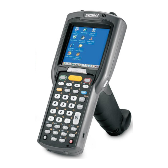
I'm seeking the - (Dash) tab on the RF Scanner. Where is it?

Summary of Contents for Symbol MC3090BT

  • Page 1 MC3000 User Guide...
  • Page 3 MC3000 User Guide 72-68899-02 Rev A October 2005...
  • Page 4 The software is provided strictly on an “as is” basis. All software, including firmware, furnished to the user is on a licensed basis. Symbol grants to the user a non-transferable and non-exclusive license to use each software or firmware program delivered hereunder (licensed program). Except as noted below, such license may not be assigned, sublicensed, or otherwise transferred by the user without prior written consent of Symbol.
  • Page 5: Revision History

    Revision History Changes to the original manual are listed below: Change Date Description -01 Rev A Dec. 2004 Initial Release -01 Rev B June 2005 Added Four Slot Ethernet cradle. Added Fabric Holster. Appendix A, added Accessory Specifications. Add Appendix C, Regulatory. -02 Rev A Sept.
  • Page 7: Table Of Contents

    Symbol Support Center ........
  • Page 8 MC3000 User Guide Demo Window ..............1-11 Waking the Mobile Computer .
  • Page 9 Contents vii Chapter 3. Using Bluetooth Introduction................3- 3 Adaptive Frequency Hopping .
  • Page 10 viii MC3000 User Guide Chapter 4. Accessories Introduction................4-3 Cradles .
  • Page 11 Contents ix Appendix B. Keypad Functions/Special Characters Introduction................B-3 Keypads .
  • Page 12 MC3000 User Guide...
  • Page 13: About This Guide

    Symbol Support Center ........
  • Page 14 MC3000 User Guide...
  • Page 15: Introduction

    The documentation set for the MC3000 is divided into guides that provide information for specific user needs. • Microsoft Application Guide - describes how to use Microsoft developed applications. • Symbol Application Guide - describes how to use Symbol developed applications. • MC3000 User Guide - describes how to use the MC3000 mobile computer.
  • Page 16: Configurations

    MC3000 User Guide Configurations This guide covers the following configurations: MC3000-R - color or monochrome display, 32MB/64MB or 64MB/64MB memory, laser scanner in rotating turret, Windows CE .NET 5.0 Core or Windows CE .NET 5.0 Professional Operating System. MC3090-G - 802.11b/g/a radio, color or monochrome display, 32MB/64MB or 64MB/64MB memory, laser scanner or imager, Windows CE .NET 5.0 Core or Windows CE .NET 5.0 Professional Operating system, optional Bluetooth radio.
  • Page 17: Notational Conventions

    • Symbol Mobility Developer Kit (SMDK) Help File, p/n 72E-38880-02 • Windows CE Platform SDK for MC3000c42a/b, available at: http://devzone.symbol.com • Symbol Mobility Developer Kit for eMbedded Visual C++ v4.0 (SMDK for eVC4), available at: http://devzone.symbol.com • Device Configuration Package for MC3000 (DCP for MC3000), available at: http://devzone.symbol.com...
  • Page 18: Service Information

    Call the Support Center from a phone near the scanning equipment so that the service person can try to talk through the problem. If the equipment is found to be working properly and the problem is symbol readability, the Support Center will request samples of bar codes for analysis at our plant.
  • Page 19 Postbus 24 7050 AA Helsfyr Panorama Varsseveld, Netherlands Innspurten 9 315-271700 (Inside Netherlands) Oslo N-0663 +31-315-271700 (Outside Netherlands) Symbol’s repair depot and shipping address: Symbol Technologies Norway Enebakkveien 123 N-0680 OSLO, Norway +47 2232 4375 South Africa Spain/España Symbol Technologies Africa Inc.
  • Page 20 Solna Strandväg 78 S-171 54 SOLNA Sweden Switchboard: 08 445 29 00 (domestic) Call Center: +46 8 445 29 29 (international) Support E-Mail: Sweden.Support@se.symbol.com If the Symbol product was purchased from a Symbol Business Partner, contact that Business Partner for service.
  • Page 21 Getting Started Chapter Contents Introduction ................1-3 Unpacking the Mobile Computer .
  • Page 22: Introduction

    • Standard battery (lithium-polymer) • Extended life battery (lithium-ion) • Cable(s) • Power supply • Cradles. Inspect the equipment for damage. If any equipment is missing or damaged, contact the Symbol Technologies Support Center immediately. See page xvi for contact information.
  • Page 23: Accessories

    Provides a soft, clip on holder and a shoulder strap for the mobile computer. Symbol Mobility Developer Kit for eMbedded Visual A development tool used to create native C and C++ applications for all Symbol mobile computers C++ v4.0 (SMDK for eVC4) running the Microsoft Windows CE operating system.
  • Page 24: Parts

    MC3000 User Guide Parts There are three versions of the MC3000 mobile computers, the MC3000 1D/2D Imager (MC3000-K or MC3090-K), the MC3000 Laser with Rotating Scan Turret (MC3000-R or MC3090-R) and the MC3090 Gun (MC3090-G). For more information on the Rotating Scan Turret, see Figure 1-3 on page 1-5.
  • Page 25: Rotating Scan Turret

    Getting Started 1-5 Headset Jack (optional) Scan Window Scan Window Strap/Door Headset Jack Assembly (optional) Screws Stylus Strap/Door Assembly Stylus Holder Latches MC3000-R MC3000-K Figure 1-2. MC3000 Imager and MC3000 Laser Mobile Computers (Back View) Rotating Scan Turret The MC3000-R mobile computer features a Rotating Scan Turret with three position stops. This feature offers greater scanning flexiblilty.
  • Page 26: Mobile Computer Startup

    MC3000 User Guide Scan LED Charge LED Beeper Indicators Indicator (red/green) (amber) Indicator LED Bar Display Scan Button Keypad Power Scan LED Indicator (red/green) Trigger Figure 1-4. MC3000-G Mobile Computer Mobile Computer Startup To start using the mobile computer: • Install the main battery. •...
  • Page 27 Getting Started 1-7 3. Insert the battery into the slot, bottom first and press the battery gently into the slot. The battery clip locks the battery into place. 4. With the latches in the open position, replace the Strap/Door Assembly, top first and press to close. 5.
  • Page 28 MC3000 User Guide Latches Strap/Door Hand Strap Assembly Battery Strap/Door Assembly Figure 1-6. Main Battery Installation (MC3000-G)
  • Page 29: Battery Charging

    Getting Started 1-9 Battery Charging Use the mobile computer cradles, cables and spare battery chargers to charge the mobile computer main battery. The main battery can be charged before insertion into the mobile computer or after it is installed. There are two main batteries for the MC3000, the Standard Battery and the Extended Life Battery.
  • Page 30: Spare Battery Charging

    1-10 MC3000 User Guide Table 1-2. Mobile Computer LED Charge Indicators Indication Mobile computer not placed correctly in the cradle; charge cable not connected correctly; charger is not powered. Fast Blinking Amber Error in charging; check placement of the mobile computer. Slow Blinking Amber Mobile computer is charging.
  • Page 31: Starting The Mobile Computer

    Getting Started 1-11 Starting the Mobile Computer When the mobile computer is powered on for the first time, it initializes. The Symbol Splash screen appears for a short period of time, followed by the Calibration screen. Figure 1-7. Symbol Splash Screen After the calibration procedure is performed the factory settings launch the Demo window.
  • Page 32: Waking The Mobile Computer

    1-12 MC3000 User Guide applications were not developed to support end users. Refer to the Symbol Application Guide for information about the Demo window applications. Figure 1-9. Demo Window Waking the Mobile Computer The wakeup condition settings are used to define what actions wake up the mobile computer. The settings are configurable so they are subject to change/update.
  • Page 33 Getting Started 1-13 b. On the MC3090-G, pull the battery pull tab to unclip the battery and lift the battery out top first. If the battery does not have a pull tab, use the stylus to unclip the battery and then lift the battery. Strap/Door Hand Strap Latches...
  • Page 34: Strap/Door Assembly Removal And Replacement (Mc3000-K/R)

    1-14 MC3000 User Guide The SD card holder is located under the battery. To install the SD card, see Secure Device Card on page 4-13. Strap/Door Assembly Removal and Replacement (MC3000-K/R) The Strap/Door Assembly consists of a hand strap and the battery door. There are two versions of this assembly, one for the Standard Battery and one for the Extended Life Battery.
  • Page 35: Strap/Door Assembly Removal And Replacement (Mc3000-G)

    Getting Started 1-15 Strap/Door Assembly Removal and Replacement (MC3090-G) The Strap/Door Assembly consists of a hand strap and the battery door. Before removing the Strap/Door Assembly, press the red Power button to turn off the screen and set the mobile computer to suspend mode. To remove the Strap/Door Assembly: 1.
  • Page 36 1-16 MC3000 User Guide...
  • Page 37 Operating the MC3000 Chapter Contents Introduction ................2-3 Power Button .
  • Page 38 MC3000 User Guide Scan LED Indicators ..............2-17 Scanning Considerations .
  • Page 39: Introduction

    Operating the MC3000 2-3 Introduction This chapter provides basic instructions for using the mobile computer and navigating the mobile computer software. Power Button Press the red Power button to toggle the mobile computer between suspend and resume. When the screen is off the mobile computer is in suspend mode and when the screen is on the mobile computer is on.
  • Page 40: 28-Key Keypad

    MC3000 User Guide 28-Key Keypad The 28-key keypad contains a Power button, application keys, scroll keys and function keys. The keypad is color-coded to indicate the alternate function key (blue) values and the alternate ALPHA key (orange) values. Note that keypad functions can be changed by an application so the mobile computer keypad may not function as described.
  • Page 41 Operating the MC3000 2-5 Table 2-2. 28-Key Descriptions (Continued) Description Scroll Left and Right Moves left and right from one item to another. Increases/decreases specified values. Produces a TAB when the blue FUNC key is activated and the right arrow key is pressed. Produces the ESC function by default.
  • Page 42: 38-Key Keypad

    MC3000 User Guide 38-Key Keypad The 38-key keypad contains a Power button, application keys, scroll keys and function keys. The keypad is color-coded to indicate the alternate function key (blue) values. Note that keypad functions can be changed by an application so the mobile computer keypad may not function as described.
  • Page 43 Operating the MC3000 2-7 Table 2-3. 38-Key Descriptions (Continued) Description Scan (yellow) Used in scanning applications, press to scan a bar code. Scroll Left and Right Moves left and right from one item to another by default. Produces a TAB when the blue FUNC key is activated and the right arrow key is pressed. Scroll Up and Down Moves up and down from one item to another by default.
  • Page 44: 48-Key Keypad

    MC3000 User Guide 48-Key Keypad The 48-key keypad contains a Power button, application keys, scroll keys and function keys. The keypad is color-coded to indicate the alternate function key (blue) values. Note, that keypad functions can be changed by an application so the mobile computer keypad may not function as described.
  • Page 45 Operating the MC3000 2-9 Table 2-4. 48-Key Descriptions (Continued) Description Numeric/Scroll/Select Numeric, scroll, select keys. Numeric by default. With the orange key activated, the 2, 4, 6, and 8 keys produce scroll functions and the 5 key produces a select function. With the .
  • Page 46: Demo Window

    The sample/demo applications are intended to be used by application developers as application development examples. These applications were not developed to support end users. Refer to the Symbol Application Guide for the Demo window applications.
  • Page 47: Taskbar

    Operating the MC3000 2-11 Taskbar The taskbar (at the bottom of the screen) displays the Start button, active programs, battery status and communication status. The taskbar icons are described in Table 2-5. The taskbar icons display the function status, indicate what programs are active and indicate the battery charge status.
  • Page 48: Battery Unknown Icon

    2-12 MC3000 User Guide Table 2-5. Taskbar Icons (Continued) Icon Description The Bluetooth Communication icon appears in the task tray and indicates that the mobile computer is communicating with another Bluetooth device. Indicates that the SHIFT button function is selected. Indicates that the FUNC button function is selected.
  • Page 49: Programs Menu

    From the Start menu, tap Programs to launch the Programs menu. The programs provided with Windows CE .NET 5.0 Professional and Windows CE .NET 5.0 Core are displayed in the Programs menu. Refer to the Symbol Application Guide, p/n 72-68901-xx and the ®...
  • Page 50: Task Manager And Properties

    2-14 MC3000 User Guide • Recycle Bin: Deleted files remain in the recycle bin until the recycle bin is emptied. Once emptied the files cannot be retrieved. Windows CE .NET 5.0 Professional desktop functions include: • My Computer: Double-tap the icon to open My Computer. •...
  • Page 51: Entering Information

    Operating the MC3000 2-15 4. Tap OK to save the settings and exit the window. Figure 2-11. Taskbar and Start Menu, General Tab Advanced Tab 1. Tap the Advanced tab to enter the Taskbar and Start Menu, Advanced tab. 2. Tap the Clear button to delete all of the documents listed in the Start - Documents entry, see Start Button on page 2-12.
  • Page 52: Entering Information Using The Keyboard Input Panel

    2-16 MC3000 User Guide Entering Information Using the Keyboard Input Panel Use the keyboard input panel (soft keyboard) to enter information in any program. To launch the keyboard input panel, tap the button on the taskbar. Tap a key to enter the value. Tap the keyboard input panel button to display or to hide the keyboard input panel. Figure 2-13.
  • Page 53: Scan Led Indicators

    The decode ranges provide the decode ranges for barcodes of specified densities. Figure 2-15 shows the laser decode ranges and Table 2-7 on page 2-18 lists the scan ranges for the selected bar code densities. The minimum element width (or “symbol density”)
  • Page 54 2-18 MC3000 User Guide is the width in mils of the narrowest element (bar or space) in the symbol. The maximum usable length of a symbol at any given range is shown below. 30.48 22.86 Note: Typical performance at 73˚ F (23˚ C) on high quality symbols.
  • Page 55: Imaging

    This process usually occurs instantaneously. Steps 2 - 4 are repeated on poor or difficult bar codes as long as the scan button remains active. Operational Modes The imager version of the mobile computer has two modes of operation: Decode Mode and Image Capture Mode. Refer to the Symbol Application Guide for the Series 3000 Demo imager application. Decode Mode Activate the scan button, the mobile computer attempts to locate and decode enabled bar codes within its field of view.
  • Page 56: Imager Decode Ranges

    Figure 2-18. Imager Aiming 2. The aiming pattern is smaller when the Imager is closer to the symbol and larger when it is farther from the symbol. Scan symbols with smaller bars or elements (mil size) closer to the unit and those with larger bars or elements (mil size) farther from the unit.
  • Page 57 Operating the MC3000 2-21 is the width in mils of the narrowest element (bar or space) in the symbol. The maximum usable length of a symbol at any given range is shown below. 15.24 12.7 10.16 Note: Typical performance at 73˚ F (23˚ C) on high quality symbols.
  • Page 58 2-22 MC3000 User Guide MC3000 Imager Decode Ranges Table 2-8. Ranges Bar Code Density Near 5.0 mil 4.5 in 6.5 in 11.43 cm 16.51cm 7.5 mil 3.3 in 10.7 in 8.38 cm 27.18 cm UPC A 2.5 in 14.2 in 6.35 cm 36.07cm 20 mil...
  • Page 59: Resetting The Mobile Computer

    To perform a cold boot: 1. Press and simultaneously hold the 1, 9 and Power keys. Do not hold down any other keys or buttons. As the mobile computer initializes, the Symbol splash window, Figure 1-7 on page 1-11, appears for about a minute.
  • Page 60: Waking The Mobile Computer

    2-24 MC3000 User Guide Waking the Mobile Computer The default wakeup conditions define what actions wakeup the mobile computer. These settings are configurable and the factory default settings shown in Table 2-9 are subject to change/update. Table 2-9. Default Wakeup Conditions Status Description Conditions for Wakeup...
  • Page 61: Connecting To The Internet On A Wireless Lan Network

    Operating the MC3000 2-25 All files copied to the RAM based folders are lost after a cold boot. Connecting to the Internet on a Wireless LAN Network The mobile computer can connect to the Internet across a wireless LAN network. The Wireless Applications utility starts automatically when the mobile computer is turned on and the wireless application icon appears in the taskbar to indicate the connection and the signal strength status.
  • Page 62 2-26 MC3000 User Guide...
  • Page 63 Using Bluetooth Chapter Contents Introduction ................3- 3 Adaptive Frequency Hopping .
  • Page 64 MC3000 User Guide Put File ............... .3-15 Connect to Internet Using Access Point.
  • Page 65: Introduction

    Bluetooth mobile computer and a Bluetooth enabled phone. The Bluetooth phone can then be used as a modem. Symbol mobile computers with Bluetooth technology use the StoneStreet One Bluetooth stack. To program Bluetooth within the mobile computer refer to the StoneStreet One SDK.
  • Page 66: Turning The Bluetooth Radio Mode On And Off

    MC3000 User Guide It is recommended: • Perform pairing in a secure environment • Keep PIN codes private and don't store the PIN codes in the mobile computer • Implement application-level security. Turning the Bluetooth Radio Mode On and Off Turn off the Bluetooth radio to save power or if entering an area with radio restrictions (e.g., an airplane).
  • Page 67: Enabling Bluetooth

    Using Bluetooth 3-5 Enabling Bluetooth To enable Bluetooth, tap Bluetooth icon - Enable Bluetooth. The Bluetooth icon changes to indicate that Bluetooth is enabled. Figure 3-2. Enable Bluetooth Bluetooth Power States Cold Boot When a cold boot is performed on the mobile computer, Bluetooth turns off. It is normal to see the Bluetooth icon appear and disappear, as well as a wait cursor, when initialization proceeds in all modes.
  • Page 68 MC3000 User Guide When switching between Wizard Mode and Explorer Mode, all active connections are closed. The following steps provide an example for using the Wizard to services for remote devices. 1. Tap the Bluetooth icon and select Show BTExplorer. The BTExplorer window appears. 2.
  • Page 69 Using Bluetooth 3-7 5. Select a device from the list and then tap Next. The Connection Favorite Options window appears. Figure 3-5. Connection Favorite Options Window 6. Select Save As Favorite check box to save this service in the Favorite view. 7.
  • Page 70: Explorer Mode

    MC3000 User Guide Explorer Mode The BTExplorer window is streamlined and easy to navigate and provides greater control to users familiar with Bluetooth functionality. The menu bar provides quick access to the options and tools used to connect to devices. Figure 3-7.
  • Page 71 Using Bluetooth 3-9 3. Tap the Bluetooth icon and select Show BTExplorer. The BTExplorer window appears. Figure 3-8. BTExplorer Window 4. Tap and hold Remote Devices and select Discover Devices from the pop-up menu. The mobile computer searches for Bluetooth devices in the area. Figure 3-9.
  • Page 72: Bonding With Discovered Device(S)

    3-10 MC3000 User Guide Bonding with Discovered Device(s) A bond is a relationship created between the mobile computer and another Bluetooth device in order to exchange information in a secure manner. Creating a bond involves entering the same PIN on the two devices to bond. Once a bond is created, and the Bluetooth radios are turned on, the devices recognize the bond and are able to exchange information without re-entering a PIN.
  • Page 73: Renaming A Bonded Device

    Using Bluetooth 3-11 7. The devices are successfully paired. The device name moves to the Trusted Devices folder. Figure 3-13. Bonded (Paired) Discovered Device Renaming a Bonded Device If it is necessary to rename a bonded device, it can be done from the BTExplorer window. 1.
  • Page 74: Deleting A Bonded Device

    3-12 MC3000 User Guide 3. The Change Device Name window appears. Figure 3-15. Change Device Name Window 4. Enter a new name for the bonded device in the text box. Tap OK. Deleting a Bonded Device If it is no longer necessary to connect with a device, delete it from the Bluetooth Bonded Devices window. 1.
  • Page 75: Discovering Services

    Using Bluetooth 3-13 2. When prompted to bond with the remote device the PIN Code Request window appears. Figure 3-17. PIN Code Request Window Connections to untrusted devices are a security risk. 3. In the PIN Code: text box, enter the same PIN that was entered on the device requesting the bond. The PIN must be between 1 and 16 characters.
  • Page 76: File Transfer Services

    3-14 MC3000 User Guide 3. The mobile computer communicates with the remote device and then lists the services under the device name. Figure 3-19. List of Discovered Services Some examples of available services are: • File Transfer Services • Dial-Up Networking Services •...
  • Page 77: Create New File Or Folder

    Using Bluetooth 3-15 8. Select a folder. The contents of the folder appear in the sub-window. Figure 3-20. Remote Device Folders 9. Tap and hold on the file. A pop-up menu appears. 10. Select the action to perform: a. New - create a new file or folder. on the remote device b.
  • Page 78: Connect To Internet Using Access Point

    3-16 MC3000 User Guide 3. Tap Open. The file is transferred from the mobile computer to the remote device. Connect to Internet Using Access Point This section explains how to access a Bluetooth-enabled LAN access point (AP) for a network connection. With this method of communication the Internet Explorer can be used to connect to a server.
  • Page 79 Using Bluetooth 3-17 6. Tap and hold on Dial-up Networking and select Connect from the pop-up menu. The Select Dial-up Networking Entry window appears. Figure 3-21. Select Dial-up Networking Entry Window If a dial-up entry is not listed, see Add a Dial-up Entry on page 3-18.
  • Page 80: Add A Dial-Up Entry

    3-18 MC3000 User Guide 16. To end a session, tap the Connection icon and then tap Disconnect in the dialog box. Add a Dial-up Entry To add a dial-up entry: 1. In the Select Dial-up Networking Entry window, tap and hold and then select Add Entry from the pop-up menu. Figure 3-23.
  • Page 81: Send A Picture

    Using Bluetooth 3-19 4. Select the Trusted Devices folder. 5. Tap the remote device folder. 6. Tap and hold on OBEX Object Push and select Connect. The OBEX Object Push window appears. 7. In the Action drop-down list, select one of the options: Send Contact Information, Swap Contact Information, Fetch Contact Information or Send a Picture.
  • Page 82: Headset Services

    3-20 MC3000 User Guide 9. Navigate to the picture that you want to send to the other device. 10. Tap Open. 11. Tap OK. The picture is sent to the other device and a confirmation dialog box appears on the other device to accept the picture.
  • Page 83: Personal Area Network Services

    Using Bluetooth 3-21 6. Tap and hold Serial Port and select Connect in the pop-up menu. The Remote Service Connection window appears. Figure 3-26. Remote Service Connection Window 7. In the Local COM Port drop-down list select a COM port. 8.
  • Page 84: Bluetooth Settings

    3-22 MC3000 User Guide Bluetooth Settings Use the BTExplorer Settings window to configure the operation of the BTExplorer application. Tap Tools - Settings. The BTExplorer Settings window appears. Device Info Tab Use the Device Info tab to configure the mobile computer’s Bluetooth connection modes. Figure 3-27.
  • Page 85: Services Tab

    Using Bluetooth 3-23 Services Tab For security reason, by default services are not enabled. Use the Services tab to add or delete Bluetooth services. Figure 3-28. BTExplorer Settings - Services Tab To add a service: 1. Tap Add. The Add Local Service window displays. Figure 3-29.
  • Page 86: Dial-Up Networking Service

    3-24 MC3000 User Guide Dial-Up Networking Service Dial-up Networking allows a dial-up modem to be accessed by other Bluetooth devices. Figure 3-30. Add Local Service Window Service Name Displays the name of the service. Service Security Select the type of security from the drop-down list; None, Authenticate or Authenticate/ Encrypt.
  • Page 87: Obex Object Push Service

    Using Bluetooth 3-25 Root Directory Select the directory that other Bluetooth devices can access. File Permissions Select the file permissions for the selected directory. Check the appropriate box to grant Read access, write access and delete access. OBEX Object Push Service OBEX Object Push allows contacts, business cards, pictures, appointments, and tasks to be pushed to the device by other Bluetooth devices.
  • Page 88: Personal Area Networking Service

    3-26 MC3000 User Guide Personal Area Networking Service Personal Area Networking hosts a Personal Area Network which allows communication with other Bluetooth devices. Figure 3-33. Personal Area Networking Window Service Name Displays the name of the service. Service Security Select the type of security from the drop-down list; None, Authenticate or Authenticate/ Encrypt.
  • Page 89: Headset Service

    Using Bluetooth 3-27 Local Baud Rate Select the communication baud rate. Local Port Options Select the port option. Headset Service Serial port allows COM ports to be accessed by other Bluetooth devices. Figure 3-35. Headset Service Window Service Name Displays the name of the service.
  • Page 90: Security Tab

    3-28 MC3000 User Guide Security Tab To adjust the security settings for an individual service, select the Services tab first, then select the individual service, then Properties. Figure 3-36. BTExplorer Settings - Security Tab Use PIN Code (Incoming Connecting) Select for automatic use of the PIN code entered in the PIN Code text box. It is recommended not to use this automatic PIN code feature.
  • Page 91: Discovery Tab

    Using Bluetooth 3-29 Discovery Tab Use the Discovery tab to set and modify discovered devices. Figure 3-37. BTExplorer Settings - Discovery Tab Inquiry Length Sets the amount of time that the mobile computer takes to discover Bluetooth devices in the area.
  • Page 92: Virtual Com Port Tab

    3-30 MC3000 User Guide Virtual COM Port Tab Use the Virtual COM Port tab to select the COM ports for Bluetooth communication. Figure 3-38. BTExplorer Settings - Virtual COM Port Tab COM4:Bluetooth Enable or disable COM Port 4. COM5:Bluetooth Enable or disable COM Port 5 COM9:Bluetooth Enable or disable COM Port 9 If an application uses one of the COM ports assigned to Bluetooth, opening this port causes the Bluetooth stack to activate and guide...
  • Page 93: Miscellaneous Tab

    Using Bluetooth 3-31 Miscellaneous Tab Figure 3-40. BTExplorer Settings - Miscellaneous Tab Highlight Connections Select the connection type to highlight when connected. In the Wizard Mode, the only option is Favorites or None. In the Explorer Mode the options are None, Tree View Only, List View Only or Tree and List View.
  • Page 94 3-32 MC3000 User Guide...

This manual is also suitable for:

Mc3000Mc3000-rMc3090-gMc3090-kMc3090-r

Table of Contents

Save PDF