Picotest M3500A User Manual
6.5 digit
Hide thumbs
Also See for M3500A:
- User manual (177 pages) ,
- Service manual (94 pages) ,
- User manual (20 pages)
Table of Contents
Advertisement
Quick Links
Download this manual
See also:
Service Manual
Advertisement
Table of Contents

Subscribe to Our Youtube Channel
Related Manuals for Picotest M3500A


Summary of Contents for Picotest M3500A
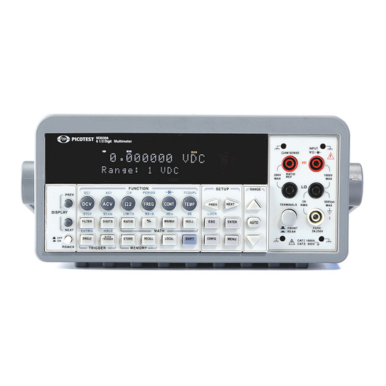
- Page 1 ® ® ® ® PICOTEST M3500A 6.5 Digit Digital Multimeter User’s Manual Version: 1.06...
- Page 2 M3500A DMM User’s Manual 2 2 2 2...
-
Page 3: Table Of Contents
1.1 F ..................... 6 EATURE VERVIEW 1.2 W ................... 7 ARRANTY NFORMATION ..................8 RECAUTION OF PERATION 1.4 U M3500A ....................9 PKEEP OF 1.5 S ....................9 AFETY NFORMATION 1.6 S ....................10 YMBOLS AND ERMS 1.7 I ........................ 11 NSPECTION 1.8 A... - Page 4 3.7.2 RTD Measurements ................44 3.7.2.1 2-Wire RTD Measurements ..............45 3.7.2.2 3-Wire RTD Measurements ..............46 3.7.2.3 4-Wire RTD Measurements ..............48 4 FRONT PANEL OPERATIONS ..................51 4.1 M ................51 EASUREMENT ONFIGURATION 4.1.1 Set ADC (Auto Zero) ................51 4.1.2 Filter ......................
- Page 5 4.4.6 Stepping (Step) ..................104 4.4.7 Initial Mode ..................... 105 4.4.8 Language ....................107 4.4.9 Error Condition ..................107 4.4.10 Firmware Revision ................108 4.4.11 Calibration Information ..............109 4.4.12 Self-Test ....................110 5 REMOTE INTERFACE OPERATIONS ................115 5.1 P USB C ............
-
Page 6: General Information
If you have any questions after reading this information, please contact your local service representative. 1.1 Feature Overview M3500A is a 6.5 digit digital multimeter. It has 0.0015% 24-hour basic DC voltage accuracy at 10V range and 0.002% 24-hour basic resistance accuracy at 10kΩ range. -
Page 7: Warranty Information
If the equipment is used in a manner not specified by the manufacturer, the protection provided by the equipment may be impaired. 1. Warranty: PICOTEST CORP. guarantees that this product meets its published specifications at the time of shipment from the factory. -
Page 8: Precaution Of Operation
No other warranty is expressed or implied, except for the above mentioned. The remedies provided herein are the buyer’s sole and exclusive remedies. PICOTEST shall not be liable for any direct, indirect, special, incidental or consequential damages. Limitation of warranty 1. -
Page 9: Upkeep Of M3500A
If the incorrect display or abnormal beeps occurred you should stop using the equipment at once. Do not use the Meter around explosive gas or inflammable vapor. Wipe the surface of M3500A multimeter with a piece of dry and clean cloth. 1.5 Safety Information Caution! Please read through the following safety information before using the product. -
Page 10: Symbols And Terms
Do not try to operate the Meter if it is damaged. Disconnect the power from the equipment and consult the local service representative. Return the product to PICOTEST service department if necessary. 1.6 Symbols and Terms This symbol indicates hazards that may cause damages to the instrument or even result in personal injury. -
Page 11: Inspection
One CD (including this electronic User's Manual and software applications). Optional accessories as you ordered. (Refer to the section 1.8 “Accessories”) The M3500A is provided with a Standard Test lead set, described below. Test Lead Ratings: IEC 61010-031 CAT III Operating Voltage: 1000V DC... -
Page 12: Accessories
Warning: If you use the Test Lead Set which is not qualified by ※ ※ ※ ※ Picotest Corp., the protection of the Test Lead Set could be impaired. In addition, please don’t use a damaged Test Lead Set against the instrument break or personal injury. -
Page 13: M3500A's Dimension
1.9 M3500A’s Dimension Please get the dimension’s information in the following different ways. 1. The dimension without the handle and the front & Rear Bumpers is in the following Picture 1. (LxWxD - 213.6x88.6x370 mm) 2. The dimension with the handle and the front & Rear Bumpers is in the following Picture 2. -
Page 14: Overview
Overview This chapter will give you an overview of M3500A’s basic features and guide you through the basics of M3500A digital multimeter. You will become familiar with those features after reading this chapter. 2.1 Setting up Your M3500A Digital Multimeter You may want to check if your multimeter is ready for measurement. - Page 15 Figure 1-1 S tep 2 ( Pull out the handle) 【 】 When the handle is turned up to 90° with the multimeter please pull out the handle from the multimeter as shown in Figure 1-2. Figure 1-2 Ⅱ Ⅱ Ⅱ Ⅱ . Adjusting the position for your convenience Here are some referable positions for your reference.
- Page 16 Figure 1-3 P osition 2 【 】 The adjusted position is for operation as shown in Figure 1-4 。 Figure 1-4 P osition 3 【 】 The carrying position is with the handle as shown in Figure 1-5 。 Figure 1-5 16 16 16 16...
-
Page 17: To Connect The Power
AC power. An incorrect voltage setting may cause severe damage to your instrument. Warning! The power cord supplied with M3500A contains a separate ground wire for use with grounded outlets. When proper connections are made, instrument chassis is connected to power line ground through the ground wire in the power cord. - Page 18 Figure 2-1 S tep 2 【 】 Open the voltage setting selector cap as shown in Figure 2-2. (You might need a screwdriver to do so.) Figure 2-2 S tep 3 【 】 Remove the red voltage setting selector from the right middle seam as shown in Figure 2-3.
- Page 19 Figure 2-3 S tep 4 【 】 Turn it over to 220V position as shown in Figure 2-4. Figure 2-4 S tep 5 【 】 Insert the voltage setting selector back into the socket and close the cap as shown in Figure 2-5. Figure 2-5 19 19 19 19...
-
Page 20: To Change The Fuse
2.1.2.2 To change the fuse Warning! Before replacing the power-line fuse, make sure the multimeter is disconnected from the AC power. You must be a qualified personnel to perform this action. Warning! For continued protection against fire or instrument damage, only replace fuse with the same type and rating. If the instrument repeatedly blows fuses, locate and correct the cause of the trouble before replacing the fuse. - Page 21 S tep 2 【 】 Open the voltage setting selector cap as shown in Figure 2-7. (You might need a screwdriver to do so.) Figure 2-7 S tep 3 【 】 Remove the red voltage setting selector from the right middle seam as shown in Figure 2-8.
- Page 22 S tep 4 【 】 Remove the broken fuse from the selector as shown in Figure 2-9. Figure 2-9 S tep 5 【 】 Replace with the new fuse as shown in Figure 2-10. Figure 2-10 S tep 6 【 】...
- Page 23 S tep 7 【 】 Make sure the power switch on the front panel is in “Power OFF” condition before plugging as shown in Figure 2-12. Figure 2-12 Power switch: “POWER OFF” S tep 8 【 】 After finishing the above procedures, you can plug in your power cord as shown in Figure 2-13.
-
Page 24: Factory Default When Power-On
S tep 9 【 】 Press on the power switch on the front panel for activating M3500A as shown in Figure 2-14. Figure 2-14 Power switch: - “POWER ON” 2.1.3 Factory Default When Power-ON Table 2-1 shows the factory default of M3500A. - Page 25 AC Digits Slow 5.5 Voltage DC digits (1 PLC) Range Auto AC Digits Slow 5.5 Current DC Digits (1 PLC) Range Auto Digits Frequency Range AUTO and Period Medium Rate (100ms) Digits Diode Test Range Rate 0.1 PLC Slow 5.5 Resistance Digits (1 PLC)
-
Page 26: Features
Easy & Free PC applications. 2.3 M3500A Function Introduction To become familiar with the M3500A DMM, picotest will provide you the brief introduction of the basic M3500A DMM operations. There are three major parts of M3500A: (2.3.1) the front panel, (2.3.2) the display, and (2.3.3) the rear panel. - Page 27 3 3 3 3 4 4 4 4 5 5 5 5 Figure 2-15 1. Power & Display: Power: Activates M3500A DMM. Display: Shows model, version & condition by pressing round PREV & NEXT buttons. 2-1. First row without SHIFT button: DCV: Selects DC voltage measurement.
- Page 28 DIGITS: Changes resolution. RATIO: Enables the dcv:dcv ratio function. %: Calculates the ratio to a target value in percentage. MIN/MAX: Captures the minimum or maximum readings from the measurement. NULL: Activates the offset function in order to get the real measured reading.
- Page 29 measuring. 3-2. The second row in SETUP section: ESC: Cancels selection, moving back to measurement display. ENTER: Accepts selection, moving to next choice or back to measurement display. LOCK: Presses SHIFT then ESC button to prevent unpredictable operation on the panel. In order to release lock condition, please press ESC again.
-
Page 30: The Display
Figure 2-16 2.3.2 The Display M3500A has a 5x7 dot matrix, dual-display with three-color W hite, Red and Yellow annunciators for a better view. There are two rows in the dual-display screen. The upper row displays readings and units. A maximum 13 characters are allowed for upper row dot-matrix display. -
Page 31: Annunciators At Upper Side
): Indicated the continuity testing is enabled. ● ● ● ● : Indicates the diode testing operation is taken. CW: Not used for Model M3500A. CC: Not used for Model M3500A. CV: Not used for Model M3500A. EXT: Indicates the External Trigger Mode is enabled. -
Page 32: The Rear Panel
2.3.3 The Rear Panel The rear panel of the M3500A is shown in Figure 2-20. This figure includes important abbreviated information that should be reviewed before using the instrument. 7 7 7 7 6 6 6 6 1 1 1 1... - Page 33 line voltage setting. Configured for line voltages of 100/220V or 120/240V. (Depend on the power utility in your area.) 6. Option Slot: Designed for installing an optional multi-point scanner card (Model: M3500-opt01 or M3500-opt09). 7. Option GPIB (IEEE488 Connection)/RS-232: Connects a remote computer with an IEEE488 cable or with a DB-9 cable for changing operation environment instead of the front panel control (Model: M3500-opt04/M3500-opt06).
-
Page 34: Basic Measurement Function
Basic Measurement Function This chapter introduces some basic measurement functions in M3500A. You will learn how to use your M3500A multimeter to measure voltage, current, resistance, frequency, period, continuity, diode temperature in this chapter. 3.1 Voltage Measurements (DC & AC) The ranges for DC voltage measurements in M3500A are 100mV, 1V, 10V, 100V and 1000V. - Page 35 Connect test leads to your source signal and observe the reading ⑥ ⑥ ⑥ ⑥ shown on the display. If the input signal is beyond the allowed range, an overflow message “OVLD” will be displayed. Figure 3-1 Figure 3-2 Note: The rear panel terminals can also be used via the same ※...
-
Page 36: Current Measurements (Dc & Ac)
Figure 3-3 3.2 Current Measurements (DC & AC) The ranges for DC current measurements in M3500A are 10mA, 100mA, 1A and 3A. For AC current measurements, the range is 1A with a sensitivity of 1 A to 3A AC-Coupled TRMS with a sensitivity of 10 μ... - Page 37 Select the auto-range function by pressing AUTO button on the front ⑤ ⑤ ⑤ ⑤ panel or use buttons to select desired range. △ ▽ Connect test leads to your source signal and observe the reading ⑥ ⑥ ⑥ ⑥ shown on the display.
-
Page 38: Resistance Measurements (2 & 4-Wire)
3.3 Resistance Measurements (2 & 4-wire) The ranges for resistance measurement are 100 , 1K , 10k , 100k , 1M , 10M , and 100M , with a sensitivity of 100 µ (on 100 range.) There are two modes for measuring the resistance: 2-wire mode as shown in Figure 3-6 and 4-wire mode as shown in Figure 3-7. - Page 39 Figure 3-6 Figure 3-7 Note: The rear terminal panel also can be used via the same ※ procedures like the front panel as shown in Figures 3-8 and 3-9. Figure 3-8 39 39 39 39...
-
Page 40: Frequency & Period Measurements
Figure 3-9 3.4 Frequency & Period Measurements M3500A uses an on-board counter with 25MHz to measure the frequency (period). The measurement band is from 3Hz to 300kHz (or 333 ms to s ) and the measurement voltages range from 100mV to 750 V in μ... -
Page 41: Continuity Measurements
3.5 Continuity Measurements M3500A uses 1 K Ω range for the continuity measurement. The meter beeps when the test resistance is less than the threshold resistance. The default threshold resistance is 10 , but you can set the threshold resistance to anything between 1 and 1 K . -
Page 42: Diode Measurements
3.6 Diode Measurements M3500A uses a current source of 1 mA for diode testing. The maximum resolution is 10 µV on a fixed range of 1 V DC. The default threshold voltage is fixed between 0.3 and 0.8 volts and the reading rate is fixed at 0.1 PLC (The voltage bound is adjustable from 0.01V up to 1.2V.). -
Page 43: Temperature Measurements
3.7 Temperature Measurements The M3500A supports thermocouples and resistance temperature detector (RTD) types of probes. For thermocouples, M3500A supports 7 types: E, J, K, N, R, S and T. Please refer to Table 3-1 for their temperature ranges. Be sure that the temperature function is configured for the right sensor type before making measurements (Refer to 4.1.8... -
Page 44: Thermocouple Measurements
3.7.1 Thermocouple Measurements Connect the thermocouple adapter to the banana jacks on the front panel. The difference between each type is subject to the patch thermal leads. Note: Only connection via the front panel can be used for temperature ※ measurements. -
Page 45: 2-Wire Rtd Measurements
3.7.2.1 2-Wire RTD Measurements How to measure temperature with 2-Wire RTD The following Figure 3-13 shows theory diagram of 2-Wire RTD measurement. Use terminals switch to select front terminals. ① ① ① ① Insert a specified adapter into the front terminals. Connect the low ②... -
Page 46: 3-Wire Rtd Measurements
Figure 3-14 3.7.2.2 3-Wire RTD Measurements How to measure temperature with 3-Wire RTD The following Figure 3-15 shows theory diagram of 3-Wire RTD measurement. Use terminals switch to select front terminals. ① ① ① ① Insert a specified adapter into the front terminals. Connect the low ②... - Page 47 TEMP and . When ready, press ENTER button. For more ◁ ▷ information, refer to the section 4.1.8. Press TEMP button. ④ ④ ④ ④ Place RTD in the desired position and take the reading on the display. ⑤ ⑤ ⑤ ⑤ Note: When you conduct the 3-wire RTD measurement, the input LO ※...
-
Page 48: 4-Wire Rtd Measurements
In Short Condition Figure 3-16 3.7.2.3 4-Wire RTD Measurements How to measure temperature with 4-Wire RTD The following Figure 3-17 shows theory diagram of 4-Wire RTD measurement. Use terminals switch to select front terminals. ① ① ① ① Insert a specified adapter into the front terminals. Connect the low ②... - Page 49 Figure 3-17 49 49 49 49...
- Page 50 Figure 3-18 50 50 50 50...
-
Page 51: Front Panel Operations
Zero The purpose of Auto Zero function is used for minimizing the offset influence on your measurements. When Auto Zero is enabled, M3500A takes the input signal reading as a base value and then internally disconnects the input signal, and takes an offset reading (a null offset). - Page 52 Defaults The default settings for Auto Zero are enabled. The user selected values for Auto Zero are stored in a volatile memory and the default settings will be restored when the meter is power-off. How to set Auto Zero You can change the Auto Zero setting through the front panel or through the remote interface operation.
-
Page 53: Filter
4.1.2 Filter Filter is used to remove noises in measurement readings. M3500A is equipped with two types of filters: AC filter and digital filter. AC filter is for AC measurements only. It also affects the speed of the multimeter to yield a measurement reading. -
Page 54: Ac Filter
detail in the subsequent sections respectively. 4.1.2.1 AC Filter Definition: You are allowed to set the bandwidth for selecting one of the three AC filters (Slow, Medium and Fast), in order to achieve either higher accuracy in low frequency measurements or faster AC settling time. Defaults The factory default is 20 Hz (Medium). -
Page 55: Digital Filter
DETector:BANDwidth {3|20|200|MIN|MAX} 4.1.2.2 Digital Filter Definition: M3500A uses an averaging digital filter to yield a reading for display from a specified number of measurement readings in the past. The past measurement readings are stored in a stack of memory. The number may be in the range of 2 to 100. - Page 56 Default The digital filter is enabled and is in moving average mode with 10 readings by default. How to enable/disable digital filter Press FILTER button to switch the digital filter function. The “FILT” anunnciator indicates the state of the digital filter. When it is lit, the filter is enabled.
-
Page 57: Resolution Setting (Digits)
4.1.3 Resolution Setting (Digits) Definition While measuring DC and resistance, resolution with the number of digits on a multimeter is visible. You can select the resolution for a specific measurement. The choices for the resolution setting are: fast 4.5, slow 4.5, fast 5.5, slow 5.5, fast 6.5 and slow 6.5. - Page 58 function buttons located on the first row of your meter's front panel. Press DIGITS button to select your desired resolution for your measurement. You can press DIGITS button several times to see how the resolution setting changes from 4.5, 5.5 to 6.5. Note: When using Method A to set the resolution, your options are 4.5 ※...
-
Page 59: Dc Input Resistance
Definition To reduce the effect of loading errors due to the input resistance, M3500A allows you to select a much larger input resistance (> 10G Ω) for low input DC voltage (100mV, 1V and 10V) measurements. This feature is only available for DC voltage measurements and it is not applicable to other measurement functions. -
Page 60: Threshold Resistance (Continuity)
Front Panel Operation Press CONFIG + DCV , and then use buttons to locate “INPUT ◁ ▷ R” option. Press ENTER to select it. Then select desired value for the input resistance by pressing button. Press ENTER to choose it. ◁... -
Page 61: Range (Manual & Auto)
Default The factory default for continuity threshold resistance is 10Ω. User’s selection is stored in a volatile memory and the default value will be restored after the meter has been turned off. How to set the threshold resistance You can change the threshold resistance only through the front panel. Press CONFIG button and then CONT button. - Page 62 for each range are 120 % of the range for maximum and 10% of the range for minimum. Default The default is auto-range. The user selected range is stored in volatile memory and the default will be restored when the meter is power-off. Please refer to Table 2-1 on page 24 for the factory default range.
-
Page 63: Rate (Integration Time)
PLC (power line cycles). One PLC for 60 Hz is 16.67 ms, and for 50 Hz is 20 ms. There are 4 different integration times in M3500A for you to select from: 0.02, 0.1, 1 and 10 PLCs. - Page 64 SENSe:VOLTage:DC:NPLCycles {0.02|0.1|1|10|MINimum|MAXimum} SENSe:VOLTage:DC:NPLCycles? [MINimum|MAXimum] SENSe:CURRent:DC:NPLCycles {0.02|0.1|1|10|MINimum|MAXimum} SENSe:CURRent:DC:NPLCycles? [MINimum|MAXimum] SENSe:RESistance:NPLCycles {0.02|0.1|1|10|MINimum|MAXimum} SENSe:RESistance:NPLCycles? [MINimum|MAXimum] SENSe:FRESistance:NPLCycles {0.02|0.1|1|10|MINimum|MAXimum} SENSe:FRESistance:NPLCycles? [MINimum|MAXimum] For frequency and period measurements, aperture time (or gate time) is analogous to integration time, and you can use the following commands to set it. Specify 10 ms (4.5 digits), 100 ms (default; 5.5 digits), or 1 second (6.5 digits).
-
Page 65: Sensor Selection For Temperature Measurements
4.1.8 Sensor Selection for Temperature Measurements The multimeter supports both thermocouple and RTD. You need to configure the multimeter for the right sensor type, units and transducer before conducting temperature measurements. Definition If the RTD is used, you have to confirm the RTD settings (incl. sensor, units and transducer) first throught the front penal operations or the remote control operation. - Page 66 “Guidelines For Realizing the International Temperature Scale of 1990”. In each subrange, the calibration constants required for that subrange are listed. Default The default sensor type, units and transducer in M3500A is PT100, ℃ and 4W RTD in order. How to set up RTD You can set up the RTD configuration either through the front panel operation or through the remote interface operation.
- Page 67 SENSe:TEMPerature:TRANsducer RTD Thermocouple Definition If you are using the thermocouple function, the selections on the M3500A are: type E, J, K, N, R, S and T. (On the other hand, other selection “SIMULATED” simulates the reference junction.) To use the the...
- Page 68 For Example: If the criterion value is (T1 =30.0°C), the reference value showing on the M3500A is (T2=24.0°C). You will get a remainder T3 (T1 – T2 = 6.0°C). Then you just configure the default simulated value from 23.0°C to 29.0°C on the M3500A.
-
Page 69: Remote Interface Selection
:UNIT? SENSe TCOuple:TYPE {E|J|K|N|R|S|T} SENSe: TCOuple:SIMulated {<value>|MINimum|MAXimum} SENSe: 4.1.9 Remote Interface Selection The multimeter supports both GPIB/RS-232 and USB interfaces, but only one interface can be activated at a time. If you are using GPIB, you must set the address for the multimeter. You can set the address to any value from 0 and 31. -
Page 70: Trigger Operations
Figure 4-7 4.2 Trigger Operations In this section we will discuss the triggering system in M3500A. M3500A provides a variety of trigger operations. You can select a trigger mode, a trigger source and different trigger settings for a specific measurement. -
Page 71: Trigger Mode
The rate of taking readings depends on the current settings. This function is only available through the front panel. The auto triggering is also the default for trigger mode in M3500A. How to use Auto Trigger Press ATUO TRIGGER on the front panel to toggle for enabling auto trigger mode. -
Page 72: Trigger Source
Figure 4-10. Figure 4-10 4.2.2 Trigger Source In M3500A, you can specify the trigger source to be one of these three options: front panel operations, external hardware trigger source and remote interface operations. - Page 73 External Triger Terminal You can trigger the M3500A by using a low-true pulse to the Ext Trig (external trigger) terminal located on the rear panel. And to use this terminal via the remote interface, you have to select the external trigger source by using the TRIGer:SOURce EXTernal command.
-
Page 74: Trigger Setting
PC terminal: TRIGger:SOURce IMMediate 4.2.3 Trigger Setting In M3500A, you can specify a variety of trigger settings including the number of samples per trigger, the number of triggers per event, reading hold, and the trigger delay for your measurements. 74 74 74 74... - Page 75 A. Number of samples on each trigger By default, the multimeter takes only one reading on each trigger, but you can instruct the multimeter to take specific number (up to 50000) of readings each time it receives a trigger. The user’s input setting is stored in a volatile memory which will be cleared after the meter has been turned off and the default value will be restored.
- Page 76 before the “idle” state. However, this can only be done through the remote interface. The following command shows how to set multiple triggers per returning idle state. TRIGger:COUNt <value> C. Reading hold The reading hold feature is used to hold a stable reading on the display. When a reading is stable, enabling the reading hold will hold the stable reading and trigger a beeping sound.
- Page 77 Defaults The default of the trigger delay is automatic. M3500A automatically selects a delay time for you according to the setting of the measurement if you do not specify a delay. A list of the default for each measurement function is shown on Table 4-4. The range for the delay is from 0 to 3600 seconds.
- Page 78 (Front Panel w/ Auto 20 Hz 200 ms Trigger On) 200 Hz 100 ms Remote Interface / 1.0 s External Frequency/Period Front Panel w/ Auto Trigger ON How to specify a delay time You can set the delay time from either the front panel operations or the remote interface operations.
-
Page 79: Math Operations
TRIGger:DELay:AUTO {OFF|ON} 4.3 Math Operations This section will introduce the mathematical operations in M3500A. There are eight math operations: RITIO, %, Min/Max, NULL, Limits, MX+B, dB and dBm testing. They either store data for later use or perform mathematical operations on the readings. Note that these math operations are available to all measurement functions except continuity and diode testing. -
Page 80: (Percent)
Press CONFIG + RATIO, and then use buttons to locate ◁ ▷ “RESOLUTION” option (Refer to 4.1.3) and “FILTER” option (Refer to 4.1.2.2). Press ENTER to make choices. Then select desired value for it by pressing button. Press ENTER to choose it. For ◁... - Page 81 The specified target value is store in a volatile memory and will be cleared after the meter has been turned off or a remote interface reset. How to use % (Percent) function There are two ways to make a percent measurement: Through the front panel operation or through the remote interface operation.
-
Page 82: Min/Max
CALCulate:STATe {OFF|ON} CALCulate:STATe? CALCulate:PERCent:TARGet {<value>|MINimum|MAXimum} CALCulate:PERCent:TARGet? [MINimum|MAXimum] 4.3.3 Min/Max Definition When the Min/Max function is enabled, the multimeter takes in a series of readings from the measurements, stores the minimum and maximum readings in the memory, and then calculates the average value of all readings. -
Page 83: Null
Figure 4-16 Remote Interface Operation The following commands show you how to use the Min/Max operation from your PC terminal. CALCulate:FUNCtion AVERage CALCulate:STATe {OFF|ON} CALCulate:STATe? CALCulate:AVERage:MINimum? CALCulate:AVERage:MAXimum? CALCulate:AVERage:AVERage? CALCulate:AVERage:COUNt? 4.3.4 Null Definition When null function is enabled, the displayed measurement reading is the difference between the measured input signal reading and the stored null (also called relative) value. - Page 84 How to use null (relative) measurement You can activate null feature from either the front panel operation or the remote interface operation. The Front Panel Operation The null measurements can be used with any function except continuity and diode. To store the null test lead resistance, short the two test leads together and then press NULL button.
-
Page 85: Limits Test
CALCulate:NULL:OFFSet < value>|MAXimum|MINimum { { { { } } } } 4.3.5 Limits Test The limits testing operation allows you to adjust a maximal and a minimal limit values. The multimeter beeps and an “HI” or “LO” message will be shown when the reading exceeds the upper or lower limit respectively. - Page 86 Figure 4-18 How to make a limit testing The locations of the buttons are shown with red rectangle frames in the Figure 4-19. Select a measurement function for purpose except continuity and diode. Enable the limit operation by pressing SHIFT + RATIO buttons. After enabling the limit function, you can set the limit value as mentioned above.
-
Page 87: Mx+B
Second, if the input current source you want to measure exceeds the current specification, 3A, of the M3500A. Then the DCV/ACV and MX+B functions would be helpful. The current value is calculated through the equation as follows. “I=V/R”. - Page 88 (via the front panel operation for the single current measurement.): Case: Mr. Obama wants to measure a source, 10A, through a 0.1Ω current shunt and a M3500A DMM. However, the DMM’s tolerance just can stand the maximum input current, 3A. What should he do? Please obey the following procedures and illustrations as a big current measurement solution.
- Page 89 1. Switch the terminal to the front control. 2. Externally connect a current shunt “0.1Ω” in parallel connection to the INPUT HI & LO and a current source 10A. 3. Press CONFIG > SHIFT + % to set the MX+B. You need to input the current shunt value “M = 1/0.1= 10Ω”...
-
Page 90: Db/Dbm
Remote Interface Operation Use the following commands to enable and configure MX+B function: CALCulate:FUNCtion MXB CALCulate:STATe {OFF|ON} CALCulate:STATe? CALCulate:MXB:MMFactor {<value>|MINimum|MAXimum} CALCulate:MXB:MMFactor? [MINimum|MAXimum] CALCulate:MXB:MBFactor {<value>|MINimum|MAXimum} CALCulate:MXB:MBFactor? [MINimum|MAXimum] 4.3.7 dB/dBm A. dB Definition The dB feature takes a DC or AC voltage measurement and displays it in decibel unit in correspondence to a relative reference value. - Page 91 locations of the buttons are shown with red rectangle frames in Figure 4-21. Figure 4-21 How to make a dB measurement Select the measurement function by pressing one of DCV and ACV buttons. Enable the dB operation by pressing SHIFT + NULL buttons. After enabling the dB operation, you can set or alter the dB relative value as mentioned above.
- Page 92 Definition With dBm selected, a voltage measurement is displayed as the level of power, relative to 1 milliwatt, dissipated through a reference resistance. The reference resistance is adjustable in M3500A. The calculation of dBm is defined as below: ...
- Page 93 Figure 4-23 How to make a dBm measurement Select a measurement function by pressing DCV or ACV button. The dBm feature is only available for DCV and ACV only. To enable dBm, press SHIFT + MIN/MAX buttons. After enabling the dBm operation, you can select the reference resistance as mentioned above.
-
Page 94: Other System Related Operations
Each system related operation performs a task that is not measurement related but plays an important role in making your measurements. 4.4.1 Display M3500A has a 5x7 dot matrix, dual-display with three-color W hite, Red and Yellow annunciators for a better view. A maximum 13 characters... - Page 95 because there is no I/O delay. But turning off the display will not affect the messages displayed from the RECALL, MENU and CONFIG operations. You can send a message through the remote interface from your PC terminal to the lower row display and will substitute the original display. Default The display default is “ON”.
-
Page 96: Beeper
(clears the message displayed) 4.4.2 Beeper M3500A multimeter beeps when some certain conditions are met or when an error occurs. But there may be time you want to disable the beeper for some operations. Although you can turn off the beeper, the click sound you hear when a button is pressed will not be disabled. -
Page 97: Reading Memory (Store & Recall)
How to use the reading memory You can store the readings and access to the stored readings through either the front panel operation or the remote interface operation. Note: Each datum stored from M3500A to remote interface will be in ※ 97 97 97 97... - Page 98 a first in and first out condition. Front Panel Operation Before using the reading memory feature, you need to select a measurement function (or the math function) first and then select the trigger mode. To store readings, use the following steps: Press STORE button, and the multimeter will start to store the readings produced until the specified number of readings is reached.
-
Page 99: Sensitivity Band (Hold)
stored. The locations of the buttons are shown with red rectangle frames in Figure 4-29. Figure 4-29 Remote Interface Operation You can use the following commands from your PC terminals to store or retrieve readings in the memory In addition, the number for STORE function only can be set through front panel. -
Page 100: Scanning (Scan)
The default band is 0.1%. Your selection is stored in a volatile memory and it will be cleared after the meter has been turned off. How to adjust the sensitivity band You can adjust the sensitivity band through either the front panel operation or the remote interface operation. - Page 101 input signals. You can open and close individual channels, set scan count and scan interval, store measurement readings and activate measuring through channels defined with different measurement functions. The measurements are taken through all defined channels in sequence. The scan count limits the total number of measurements the multimeter makes through all defined channels in one single scanning operation.
- Page 102 Common Mode Voltage: 350V peak between any terminal and earth. Maximum Voltage Between Any Two Terminals: 200V peak. Maximum Voltage Between Any Terminal and M3500A Input LO: 200V peak. ENVIRONMENTAL: Meets all M3500A environmental specifications. M3500A-opt01 Scanner Card Configuration & Speed List:...
- Page 103 AutoZero OFF,AutoGain OFF,AutoRange OFF, Scan Timer=0,60Hz rate(ch/s) NPLC Take Time with 2000 Readings(sec) (Fast 4.5) 0.02 29.4 single 27.0 (Slow 4.5 & Fast 5.5) 0.1 function(VDC) 19.0 (Slow 5.5 & Fast 6.5) 1 (Slow 6.5) 10 AutoZero OFF,AutoGain OFF,AutoRange OFF, Scan Timer=0,60Hz rate(ch/s) NPLC Take Time with 2000 Readings(sec)
-
Page 104: Stepping (Step)
to move through the digits and a nd to increase or ◁ ▷ △ ▽ decrease the numbers to the desired channel number. Press ENTER to close the channel. To open all channels, simply press ENTER on “OPEN ALL” option. Press SHIFT + DIGITS to scan. The locations of the buttons are shown with red rectangle frames in Figure 4-31. -
Page 105: Initial Mode
Press CONFIG + SHIFT + FILTER for scanning configuration. Use ◁ buttons to scroll through submenus. Press ENTER to select ▷ “OPERATION” submenu. Use to switch among scan count ◁ ▷ (COUNT), scan interval (TIMER) and store (STORE) options. Then press ENTER on your selection. - Page 106 “SAVE DATE” to save the current configuration or select “DEFAULT” to restore the factory value after restarting M3500A. The valid range of “SAVE DATA” is listed in Table 4-5. T a b l e 4 T a b l e 4 - - - - 5 5 5 5...
-
Page 107: Language
Figure 4-33 4.4.8 Language M3500A supports two languages: DEFAULT (M3500A) and COMPATIBLE. How to set up the language Press MENU and then use to locate “SYSTEM” submenu. Press ◁ ▷ ENTER to select it. Again use to locate “LANGUAGE” submenu. -
Page 108: Firmware Revision
The locations of the buttons are shown with red rectangle frames in Figure 4-35. Figure 4-35 4.4.10 Firmware Revision M3500A has three microprocessors for various internal systems. You can query the multimeter to determine which revision of firmware is installed... -
Page 109: Calibration Information
4-36. Figure 4-36 4.4.11 Calibration Information M3500A will show the latest calibrated date and the next calibration date on the display after following the operation below. The location of the buttons is shown with red rectangle frames in Figure 4-37. -
Page 110: Self-Test
For more calibration procedure information, please contact your local distributor. 4.4.12 Self-Test Self-test procedures are built in M3500A for checking that the logic and measurement hardware are functioning properly. Every time when the multimeter is powered on, a set of test procedures is performed to make sure the basic function of the multimeter works properly. - Page 111 Figure 4-38 → → Procedure: MENU SYSTEM SELF TEST After self-test procedure, the result, PASS or FAIL, will be shown. If the result is FAIL, the “ERR” annunciator on the display panel will be lit, and error codes will be stored. You can check the error codes by the following procedure.
- Page 112 605 N2 calibration parameter failed This error message indicates that N2 calibration parameter is out of range. 606 N3 calibration parameter failed This error message indicates that N3 calibration parameter is out of range. 607 Buffer1 offset out of range This procedure is to test the offset of ±...
- Page 113 615 Ohms 10 uA source failed This test configures to the 1000V dc range with the internal 10M 100:1 divider R204 connected across the µ input. The 10 A ohms current source is connected. The compliance limit of the current source is measured. A 20ms ADC measurement is ±...
- Page 114 input capacitor C614. This produces a pulse on the output of the rms-to-dc converter which is sampled 100ms after the current is applied. A 20ms A/D measurement is performed and checked against a limit of 2V to 13V into the ADC. 622 DC 10V reference failed This test configures to the 10V dc range with 5V input applied.
-
Page 115: Remote Interface Operations
Remote Interface Operations M3500A supports three remote interfaces: the built-in USB (USBTMC), optional GPIB (IEEE-488) and RS-232. With GPIB/RS-232, you will need a GPIB/RS-232 interface card. This chapter lists the SCPI (Standard Commands for Programmable Instrument) commands available to control the multimeter. For the first time to use SCPI, you’d better to refer to Appendix B. - Page 116 How to connect a computer or Terminal with the RS-232 To connect the M3500A to a computer or terminal, a proper interface cable is essential. Most computers and terminals belong to DTE (Data Terminal Equipment) devices including the DMM. You must apply a DTE-to-DTE interface cable, which is commonly called null-modem, modem-eliminator, or crossover cable (DB-9, Female to Female pin).
-
Page 117: Pass/Fail Output Via Usb Connector
5.1 Pass/Fail Output via USB Connector The USB connector, which comforns to USBTMC protocol, on the rear panel of M3500A is a series “B” connector. When the USB interface is disabled (IEEE-488 interface is selected), the internal pass and fail TTL output signals (limit testing) will be transmitted via the USB port. -
Page 118: Setting Up For Remote Interface
USB or GBIP interface. How to set up for USB interface The USB cord should be connected well between M3500A and your PC. Install the M3500A application in your PC and execute the program. Click Tool tab for Command Control, then type in your command. -
Page 119: Remote Interface Commands
How to set up for GPIB interface Insert GPIB interface card into the interface slot on the rear panel. Install the M3500A application in your PC and execute the program. Click Tool tab for Command Control, then type in your command. The icons and buttons are shown with red rectangle frames in Figures 5-1, 5-2 and 5-3. - Page 120 PERiod? {<range>|MIN|MAX|DEF},{<resolution>|MIN|MAX|DEF} CONTinuity? DIODe? TCOuple TEMPerature? The CONFigure Command The CONFigure command offers a little more flexibility than the MEASure? Command. The multimeter sets the parameters for the requested function, range and resolution, but does not make the measurements. You have an option to change the configuration.
- Page 121 output buffer right away. You must enter the reading data into your bus controller or the multimeter will stop making measurements when the output buffer fills. Readings are not stored in the multimeter’s internal memory when using the READ? Command. Using the READ? Command has a similar effect as using the INITiate command followed immediately by the FETCh? command, except readings are not buffered internally.
- Page 122 FUNCtion “PERiod” FUNCtion “CONTinuity” FUNCtion “DIODe” FUNCtion “TCOuple” FUNCtion “TEMPerature” FUNCtion? [SENSe:] VOLTage:DC:RANGe {<range>|MINimum|MAXimum} VOLTage:DC:RANGe? [MINimum|MAXimum] VOLTage:AC:RANGe {<range>|MINimum|MAXimum} VOLTage:AC:RANGe? [MINimum|MAXimum] CURRent:DC:RANGe {<range>|MINimum|MAXimum} CURRent:DC:RANGe? [MINimum|MAXimum] CURRent:AC:RANGe {<range>|MINimum|MAXimum} CURRent:AC:RANGe? [MINimum|MAXimum] RESistance:RANGe {<range>|MINimum|MAXimum} RESistance:RANGe? [MINimum|MAXimum] FRESistance:RANGe {<range>|MINimum|MAXimum} FRESistance:RANGe? [MINimum|MAXimum] FREQuency:VOLTage:RANGe {<range>|MINimum|MAXimum} FREQuency:VOLTage:RANGe? [MINimum|MAXimum] PERiod:VOLTage:RANGe {<range>|MINimum|MAXimum} PERiod:VOLTage:RANGe? [MINimum|MAXimum] [SENSe:]...
- Page 123 FRESistance:RANGe:AUTO? FREQuency:VOLTage:RANGe:AUTO {OFF|ON} FREQuency:VOLTage:RANGe:AUTO? PERiod:VOLTage:RANGe:AUTO {OFF|ON} PERiod:VOLTage:RANGe:AUTO? [SENSe:] VOLTage:DC:RESolution {<resolution>|MINimum|MAXimum} VOLTage:DC:RESolution? [MINimum|MAXimum] VOLTage:AC:RESolution {<resolution>|MINimum|MAXimum} VOLTage:AC:RESolution? [MINimum|MAXimum] CURRent:DC:RESolution {<resolution>|MINimum|MAXimum} CURRent:DC:RESolution? [MINimum|MAXimum] CURRent:AC:RESolution {<resolution>|MINimum|MAXimum} CURRent:AC:RESolutioin? [MINimum|MAXimum] RESistance:RESolution {<resolution>|MINimum|MAXimum} RESistance:RESolution? [MINimum|MAXimum] FRESistance:RESolution {<resolution>|MINimum|MAXimum} FRESistance:RESolution? [MINimum|MAXimum] [SENSe:] UNIT {Cel|Far|K} UNIT? TCOuple:TYPE {E|J|K|N|R|S|T} TCOuple:TYPE? TCOuple:SIMulated {<value>|MINimum|MAXimum} TCOuple:SIMulated? [SENSe:] TEMPerature:RTD:TYPE {PT100|D100|F100|PT385|PT3916|USER|SPRTD|NTCT}...
- Page 124 TEMPerature:RTD:DELTa {<value>|MINimum|MAXimum} TEMPerature:RTD:DELTa? [MINimum|MAXimum] TEMPerature:SPRTD:RZERo {<value>|MINimum|MAXimum} TEMPerature:SPRTD:RZERo? [MINimum|MAXimum] TEMPerature:SPRTD:A4 {<value>|MINimum|MAXimum} TEMPerature:SPRTD:A4? [MINimum|MAXimum] TEMPerature:SPRTD:B4 {<value>|MINimum|MAXimum} TEMPerature:SPRTD:B4? [MINimum|MAXimum] TEMPerature:SPRTD:AX {<value>|MINimum|MAXimum} TEMPerature:SPRTD:AX? [MINimum|MAXimum] TEMPerature:SPRTD:BX {<value>|MINimum|MAXimum} TEMPerature:SPRTD:BX? [MINimum|MAXimum] TEMPerature:SPRTD:CX {<value>|MINimum|MAXimum} TEMPerature:SPRTD:CX? [MINimum|MAXimum] TEMPerature:SPRTD:DX {<value>|MINimum|MAXimum} TEMPerature:SPRTD:DX? [MINimum|MAXimum] [SENSe:] VOLTage:DC:NPLCycles {0.02|0.1|1|10|MINimum|MAXimum} VOLTage:DC:NPLCycles? [MINimum|MAXimum] CURRent:DC:NPLCycles {0.02|0.1|1|10|MINimum|MAXimum} CURRent:DC:NPLCycles? [MINimum|MAXimum] RESistance:NPLCycles {0.02|0.1|1|10|MINimum|MAXimum} RESistance:NPLCycles? [MINimum|MAXimum] FRESistance:NPLCycles {0.02|0.1|1|10|MINimum|MAXimum}...
- Page 125 [SENSe:] AVERage:TCONtrol {MOVing|REPeat} AVERage:TCONtrol? AVERage:COUNt {<value>|MINimum|MAXimum} AVERage:COUNt? [MINimum|MAXimum] AVERage:STATe {OFF|ON} AVERage:STATe? [SENSe:] ZERO:AUTO {OFF|ONCE|ON} ZERO:AUTO? GAIN:AUTO {OFF|ONCE|ON} GAIN:AUTO? INPut: IMPedance:AUTO {OFF|ON} IMPedance:AUTO? Scanner Card Configuration Commands ROUTe:CLOSe <channel> ROUTe:CLOSe? ROUTe:OPEN ROUTe:STATe? ROUTe:SCAN:FUNCtion <channel>,{<function>|“VOLT:DC”|“VOLT:AC”| “FREQuency”|“RESistance”|“FRESistance”|“NONE”} ROUTe:SCAN:FUNC? <channel> ROUTe:SCAN:TIMER? ROUTe:SCAN:TIMER <value> ROUTe:SCAN:COUNT? ROUTe:SCAN:COUNT <value>...
- Page 126 MATH OPERATION Commands There are eight math operations. Only one of them can be enabled at a time. They either store data for later use or perform mathematical operations on the readings. Note that these eight math operations are available to all measurement functions except continuity and diode testing.
- Page 127 DATA:FEED RDG_STORE,{“CALCulate”|””} DATA:FEED? TRIGGERING M3500A provides some variant trigger operations. You can select a trigger mode, a trigger source and different trigger settings for a specific measurement. Refer to Figure 4-8 for triggering system flow chart. Triggering from a remote interface is a multi-step sequence. You must first configure the mulitmeter by choosing the desired function, range and resolution.
- Page 128 Triggering Commands INITiate READ? TRIGger: SOURce {BUS|IMMediate|EXTernal} SOURce? TRIGger: DELay {<seconds>|MINimum|MAXimum} DELay? [MINimum|MAXimum] TRIGger: DELay:AUTO {OFF|ON} DELay:AUTO? SAMPle: COUNt {<value>| MINimum|MAXimum } COUNt? [MINmum|MAXimum ] TRIGger: COUNt {<value>| MINimum|MAXimum|INFinite } COUNt? [MINmum|MAXimum] SYSTEM-RELATED Commands Each system related operation performs a task that is not measurement related but plays an important role in making your measurements.
- Page 129 SYSTem: BEEPer BEEPer:STATe {OFF|ON} BEEPer:STATe? SYSTem:ERRor? SYSTem:VERSion? DATA:POINts? SYSTEM:IDNSTR “MANUFACTURER,PRODUCT” *RST *IDN? STATUS REPORTING Commands SYSTem:ERRor? STATus: QUEStionable:ENABle <enable value> QUEStionable:ENABle? QUEStionable:EVENt? STATus:PRESet *CLS *ESE <enable value> *ESE? *ESR? *OPC *OPC? *PSC {0|1} *PSC? *SRE <enable value> *SRE? *STB?
- Page 130 Other Interface Commands SYSTem:LOCal SYSTem:REMote IEEE-488.2 COMMON Commands *CLS *ESE <enable value> *ESE? *ESR? *IDN? *OPC *OPC? *PSC {0|1} *PSC? *RST *SRE <enable value> *SRE? *STB? *TRG...
-
Page 131: Error Messages
Errors are retrieved in first-in-first-out (FIFO) order. The first error returned is the first error that was stored. When you read all errors from the queue, the ERROR annunciator turns off. M3500A beeps once each time an error occurs. Should more than 20 errors have existed, the last error stored in the queue (the most recent error) is replaced with -350, “Too many errors”. - Page 132 -104 Data type error A parameter type error was found in the command string. -105 GET not allowed A Group Execute Trigger (GET) is not allowed in the command string. -108 Parameter not allowed More parameters were found than needed for the command . -109 Missing parameter Not enough parameters were received for the command.
- Page 133 -148 Character not allowed A discrete parameter was received but a character string or a numeric parameter was expected. -151 Invalid string data An invalid character string was received. -158 String data not allowed A character string was received but not allowed for the command. -160~-168 Block data errors Block data is not acceptable.
- Page 134 -222 Data out of range A numeric parameter value is out of range. -223 Too much data A character string was too long. -224 Illegal parameter value A discrete parameter was received which was not a valid choice for the command.
- Page 135 531 Insufficient memory There is not enough memory to store the requested number of readings in internal memory using the INITiate command. The product of the sample count (SAMPle:COUNt) and the trigger count (TRIGger:COUNt) must not exceed 512 readings. 532 Cannot achieve requested resolution The multimeter cannot achieve the requested measurement resolution.
-
Page 136: Appendix
Appendix This appendix contains the performance specifications of the M3500A. It covers the AC, DC, Resistance, Temperature, and Frequency/Period characteristics under a variety of conditions. It also contains the general characteristics and accuracy calculations for your convenience. A lot of efforts are made to make sure these specifications serve your needs for production, engineering and/or research purposes. - Page 137 1 Year Shunt Function Range Resolution Resistance (23°C ± 5°C) 10.00000mA 10 nA 5.1Ω 0.050 + 0.020 100.0000mA 100 nA 5.1Ω 0.050 + 0.005 1.000000A 1 uA 0.1Ω 0.100 + 0.010 Current) 3.00000A 10 uA 0.1Ω 0.120 + 0.020 1 Year Function Range Test Current...
-
Page 138: Frequency And Period Characteristics
Frequency and Period Characteristics Accuracy ± (% of reading) 1 Year Function Frequency (Hz) Range 23º C±5º C 0.10 100mV 5-10 Frequency 0.05 & 10-40 0.03 Period 750V 40-300K 0.01 AC Characteristics Accuracy ± (% of reading + % of range) 1 Year Frequency Function... - Page 139 20-50K 0.12 + 0.05 50K – 100K 0.60 + 0.08 100K – 300K 4.00 + 0.50 1.00 + 0.03 5-10 0.35 + 0.03 1.0 uV 1.000000V 10-20K 0.06 + 0.03 20-50K 0.12 + 0.05 750.000V 50K – 100K 0.60 + 0.08 100K –...
-
Page 140: General Specifications
B. General Specifications item Limitation & description Power Supply 100V/120V/220V/240V ± 10% Power Line Frequency 50/60 Hz ± 10% Power Consumption 25 VA peak (16 W average) Operating Temperature 0 ℃ to 40 ℃ Maximum relative humidity 80% for temperature up to 31 ℃ Operating Humidity Decreasing linearly to 50 percent relative humidity at 40 ℃... -
Page 141: Remote Interface Reference
C. Remote Interface Reference C.1 An Introduction to the SCPI Language SCPI (Standard Commands for Programmable Instruments) is an ASCII-based instrument command language designed for test and measurement instruments. Refer “Simplified Programming Overview,” for an introduction to the basic techniques used to program the multimeter over the remote interface. - Page 142 Command Format Used in This Manual The format used to show commands in this manual is shown below: VOLTage:DC:RANGe {<range>|MINimum|MAXimum} The command syntax shows most commands (and some parameters) as a mixture of upper- and lower-case letters. The upper-case letters indicate the abbreviated spelling for the command.
- Page 143 You can query the current value of most parameters by adding a question mark ( ? ) to the command. For example, the following command sets the sample count to 10 readings: "SAMP:COUN 10" You can query the sample count by executing: "SAMP:COUN?"...
- Page 144 in length, and may include one or more parameters. The command keyword is separated from the first parameter by a blank space. Use a semicolon ( ; ) to separate multiple commands as shown below: "*RST; *CLS; *ESE 32; *OPC?" SCPI Parameter Types The SCPI language defines several different data formats to be used in program messages and response messages.
-
Page 145: Output Data Formats
INPut:IMPedance:AUTO {OFF|ON} String Parameters String parameters can contain virtually any set of ASCII characters. A string must begin and end with matching quotes; either with a single quote or with a double quote. You can include the quote delimiter as part of the string by typing it twice without any characters in between. - Page 146 resolution. The reading is sent to the output buffer. MEASure:VOLTage:DC:RATio? {<range>|MIN|MAX|DEF },{<resolution>|MIN|MAX|DEF} Preset and make a dc:dc ratio measurement with the specified range and resolution. The reading is sent to the output buffer. For ratio measurements, the specified range applies to input signal, yet autorange is selected for the reference signal.
-
Page 147: The Configure Command
MEASure:PERiod? {<range>|MIN|MAX|DEF},{<resolution>|MIN|MAX|DEF} Preset and make a period measurement with the specified range and resolution. The reading is sent to the output buffer. For period measurements, the meter uses only one “range” for all inputs between 0.33 seconds and 3.3 s ec. With μ... - Page 148 Preset and configure the multimeter for AC voltage measurements with the specified range and resolution. This command does not initiate the measurement. For AC measurement, resolution is fixed at 6½ digits. Therefore the resolution parameter only affects the front panel display. CONFigure:CURRent:DC {<range>|MIN|MAX|DEF},{<resolution>|MIN|MAX|DEF} Preset and configure the multimeter for DC current measurements with the specified range and resolution.
-
Page 149: The Measurement Configuration Command
seconds and 3.3 sec. With no input signal applied, period measurements return “0”. CONFigure:CONTinuity Preset and configure for a continuity measurement. This command does not initiate the measurement. The range and resolution are fixed at 1kΩ and 5½ digits respectively. CONFigure:DIODe Preset and configure for a diode measurement. - Page 150 Select a range for the selected function. For frequency and period measurements, range applies signal’s input voltage, frequency (use FREQuency:VOLTage or PERiod:VOLTage). MIN selects the lowest range for the selected function. MAX selects the highest range. [SENSe:]<function>:RANGe? [MINimum|MAXimum] Query the range for the selected function. For frequency and period, use FREQuency:VOLTage or PERiod:VOLTage.
- Page 151 Query thermocouple sensor type. [SENSe:]TCOuple:RJUNction:RSELect {REAL|SIMulated } Select a reference junction type, real or simulated. [SENSe:]TCOuple:RJUNction:RSELect? Query the reference junction type, real or simulated. [SENSe:]TCOuple:RJUNction:SIMulated {<value>|MINimum|MAXimum} Set the default temperature of the simulated reference junction. [SENSe:]TCOuple:RJUNction:SIMulated? Query the default temperature of the simulated reference junction. [SENSe:]TCOuple:RJUNction:REAL:OFFSet {<value>|MINimum|MAXimum} Set the offset voltage of the real reference junction.
- Page 152 [SENSe:]TEMPerature:RTD:BETA {<value>|MINimum|MAXimum} Set the beta constant for the user type. [SENSe:]TEMPerature:RTD:BETA? [MINimum|MAXimum] Query the beta constant for the user type. [SENSe:]TEMPerature:RTD:DELTa {<value>|MINimum|MAXimum} Set the delta constant for the user type. [SENSe:]TEMPerature:RTD:DELTa? [MINimum|MAXimum] Query the delta constant for the user type. [SENSe:]TEMPerature:SPRTD:RZERo {<value>|MINimum|MAXimum} Set the sensor R value at 0 degree Celsius.
- Page 153 Set the B coefficient. [SENSe:]TEMPerature:SPRTD:BX? [MINimum|MAXimum] Query the B coefficient. [SENSe:]TEMPerature:SPRTD:CX {<value>|MINimum|MAXimum} Set the C coefficient. [SENSe:]TEMPerature:SPRTD:CX? [MINimum|MAXimum] Query the C coefficient. [SENSe:]TEMPerature:SPRTD:DX {<value>|MINimum|MAXimum} Set the D coefficient. [SENSe:]TEMPerature:SPRTD:DX? [MINimum|MAXimum] Query the D coefficient. [SENSe:]TEMPerature:TRANsducer FRTD Set the RTD Measurement to 4-Wire. [SENSe:]TEMPerature:TRANsducer RTD Set the RTD Measurement to 2-Wire.
- Page 154 [SENSe:]PERiod:APERture{0.01|0.1|1|MINimum|MAXimum} Set the gate time (or aperture time) for period function. Specify 10 ms (4.5 digits), 100 ms (default; 5.5 digits), or 1 second (6.5 digits). [SENSe:]PERiod:APERture? [MINimum|MAXimum] Query the gate time (or aperture time) for period function. [SENSe:]DETector:BANDwidth {3|20|200|MINimum|MAXimum} Specify the lowest frequency expected in the input signal.
- Page 155 INPut:IMPedance:AUTO? Query the input resistance mode. Returns “1”(ON) or “0”(OFF). ROUTe:TERMinals? Query the multimeter to determine if the front or rear input terminals are selected. Returns "FRON" or "REAR" ROUTe:CLOSe <channel> Set channels which need to be closed. <The range is from channel 1 to 10> ROUTe:CLOSe? Query channels which were closed.
-
Page 156: The Math Operation Command
ROUTe:SCAN:COUNT <value> Set the number of times of scanning. ROUTe:SCAN:STATe? Query a channel numeric which is being scanned. ROUTe:SCAN:SCAN Run SCAN mode ROUTe:SCAN:STEP Run STEP mode C.6 The Math Operation Command CALCulate:FUNCtion {PERCent|AVERage|NULL|LIMit|MXB|DB|DBM} Select the math function. Only one function can be enabled at a time. The default function is percent. - Page 157 CALCulate:AVERage:MINimum? Read the minimum value found during the Min/Max operation. The multimeter clears the value when Min/Max is turned on, when the power has been off or a remote interface reset. CALCulate:AVERage:MAXimum? Read the maximum value found during the Min/Max operation. The multimeter clears the value when Min/Max is turned on, when the power has been off or a remote interface reset.
- Page 158 CALCulate:LIMit:UPPer? Query the upper limit for the limit testing. CALCulate:MXB:MMFactor {<value>|MINimum|MAXimum} Set the value of M. CALCulate:MXB:MMFactor? [MINimum|MAXimum] Query the value of M. CALCulate:MXB:MBFactor {<value>|MINimum|MAXimum} Set the value of B. CALCulate:MXB:MBFactor? [MINimum|MAXimum] Query the value of B. CALCulate:DB:REFerence {<value>|MINimum|MAXimum} Store a relative value in the dB Relative Register. You must turn on the math operation before writing to the math register.
-
Page 159: The Triggering Commands
useful with the Min/Max operation since it allows you to determine an average of the readings without storing the individual values. An error will be generated if you attempt to transfer readings to the output buffer using the FETCh? command. DATA:FEED? Query the reading memory state. -
Page 160: The System-Related Commands
TRIGger:DELay? Query the trigger delay time. TRIGger:DELay:AUTO {OFF|ON} Disable or enable a automatic trigger delay. The delay is determined by function, range, integration time, and ac filter setting. Specifying a delay time automatically turns off the automatic trigger delay. TRIGger:DELay:AUTO? Query the automatic trigger delay mode. - Page 161 required triggering condition is met after the READ? command is received. Measurement readings are sent to the output buffer immediately. DISPlay {OFF|ON} Turn off or on the display. DISPlay? Query the display setting. Returns “0” (OFF) or “1” (ON). DISPlay:TEXT <quoted string> Show a message on the front panel display.
-
Page 162: The Scpi Status Pattern
Set to the default identification string. Set to the compatible identification string. SYSTEM:IDNSTR "Manufacturer,Product" Change the multimeter’s identification string, such as the maker’s and the product’s names (be sure to dimension a string variable with at most 39 characters). DATA:POINts? Query the number of readings stored in the multimeter’s internal memory. - Page 163 Standard Event Register and the Questionable Data Register. The Status Byte Register collects and records high-level summary information which is reported in other register groups. With the following diagram illustration, you would make themselves clear for the SCPI status system. In addition, the Standard Event and the Questionable Data Registers have event registers which belong to read-only registers and report defined conditions in a multimeter.
- Page 164 About the Status Byte The conditions from other status registers will be reported by the status byte summary register. The query data, waiting in the multimeter’s output buffer, is reported immediatedly through the “message available” in bit 4. Besides, bits are not latched in the summary registers. In addition, to clear an event register will clear the according bits in the status byte summary register.
- Page 165 Decimal Definition Value Set to 0. Not Used Set to 0. Not Used Set to 0. Not Used One or more bits are set in the questionable data register (Bits have Questionable Data to be “enabled” in enable register). Data in the DMM’s output buffer is available. Message Available One or more bits are set in the Standard Event Register (Bits have to Standard Event...
- Page 166 service. You send the IEEE-488 serial poll message to read the status byte summary register. And to query the summary register will return a decimal value corresponding to the binary-weighted sum of the bits set in the register. And serial poll will clear the “request service bit” automatically in the status byte summary register, but no other bits are affected, i.e.
- Page 167 Enable “operation complete” by using the *ESE 1 command. Send the *OPC? command and enter the result to enable synchronization. When bit 5 is set in the status byte summary register, please use a serial poll to check. Then you could set the DMM for an SRQ interrupt by using *SRE 32.
- Page 168 register, all conditions will be reported in the standard event summary bit. At the moment, you have to write a decimal value by using the *ESE command to set the enable register mask. Note 1: The errors in the DMM’s error queue except reading the error ※...
- Page 169 You execute a *ESE 0 command. Note: When the DMM is powered on, the standard event enable ※ register won’t be cleared if you have set the DMM previously by using *PSC 0. About the Questionable Data Register The questionable data register reports the quality of the DMM’s measurement results, as well overload conditions and high/low limit test results.
-
Page 170: Status Reporting Commands
The following conditions will clear the questionable data event register. You execute a *CLS command. You query the event register by using STATus:QUEStionable:EVENt?. The following conditions will clear the questionable data enable register. You turn on the power without using *PSC command. You execute the STATus:PRESet command. - Page 171 *ESE <enable value> Enable bits in the Standard Event enable register. The selected bits are then reported to the Status Byte. *ESE? Query the Standard Event enable register. The multimeter returns a decimal value which corresponds to the binary-weighted sum of all bits set in the register.
-
Page 172: Scpi Compliance Information
C.11 SCPI Compliance Information This section encloses a list of commands that are device-specific to the M3500A. Although not included in the 1999.0 version of the SCPI standard, these commands are compliant to the SCPI format and they follow the syntax rules of the standard. - Page 173 PERiod:VOLTage:RANGe:AUTO {OFF|ON} PERiod:VOLTage:RANGe:AUTO? ZERO:AUTO? CALCulate: PERCent:TARGet {<value>|MINimum|MAXimum} PERCent:TARGet? [MINimum|MAXimum] AVERage:MINimum? AVERage:MAXimum? AVERage:AVERage? AVERage:COUNt? NULL:OFFSet {<value>|MINimum|MAXimum} NULL:OFFSet? [MINimum|MAXimum] LIMit:LOWer {<value>|MINimum|MAXimum} LIMit:LOWer? [MINimum|MAXimum] LIMit:UPPer {<value>|MINimum|MAXimum} LIMit:UPPer? [MINimum|MAXimum] MXB:MMFactor {<value>|MINimum|MAXimum} MXB:MMFactor? [MINimum|MAXimum] MXB:MBFactor {<value>|MINimum|MAXimum} MXB:MBFactor? [MINimum|MAXimum] DB:REFerence {<value>|MINimum|MAXimum} DB:REFerence? [MINimum|MAXimum] DBM:REFerence {<value>|MINimum|MAXimum} DBM:REFerence? [MINimum|MAXimum] CONFigure: CONTinuity DIODe...
-
Page 174: Ieee-488 Compliance Information
C.12 IEEE-488 Compliance Information IEEE-488.2 Common Commands *CLS *ESE <enable value> *ESE? *ESR? *IDN? *OPC *OPC? *PSC {0|1} *PSC? *RST *SRE <enable value> *SRE? *STB? *TRG Dedicated Hardware Lines Addressed Commands Attention Interface Clear Remote Enable Service Request Interrupt Device Clear... - Page 175 End or Identify Message Terminator Group Execute Trigger Go to Local Local Lock-Out Selected Device Clear Serial Poll Disable Serial Poll Enable Using Device Clear to Halt Measurements Device clear is an IEEE-488 low-level bus message which can be used to halt measurements in progress.
-
Page 176: About Application Programs
Visual Basic: Explore the Samples. Visual C++ In an MFC application, you can override PICOTEST IOUtils interfaces in a class as well as provide additional interfaces. The example in this article illustrates how to override an interface in a class while preserving the original interface implementation so that it can be delegated to by the new interface implementation. - Page 177 How to: Change the Startup Object for an Application The Startup Object property for a project defines the entry point to be called when the application loads; generally this is set to either the main form in your application or to the Sub Main procedure that should run when the application starts.
- Page 178 Dim desc As String * VI_FIND_BUFLEN Dim nList As Long Dim ret As Long Dim readin As String * 64 stat = viOpenDefaultRM(dfltRM) If (stat < VI_SUCCESS) Then 'Rem Error initializing VISA ... exiting MsgBox "USBTMC resource not found.", vbExclamation, "M3500 multimeter device test"...
- Page 179 stat = viClose(fList) Exit Sub End If Rem send Clear command '*CLS'-- Clear M3500 status register stat = viWrite(sesn, "*CLS", 4, ret) If (stat < VI_SUCCESS) Then MsgBox "System command error. (*CLS)", vbExclamation, "M3500 multimeter device test" stat = viClose(fList) Exit Sub End If Rem send measure command -- Set to 0.1 volt dc range...
- Page 180 stat = viClose(fList) Exit Sub End If stat = viClose(sesn) stat = viClose(fList) stat = viClose(dfltRM) MsgBox "End of Job." End Sub Using CONFigure with a Math Operation The following example uses CONFigure with the dBm math operation. The CONFigure command gives you a little more programming flexibility than the MEASure? command.
- Page 181 Dim stat As ViStatus Dim dfltRM As ViSession Dim sesn As ViSession Dim fList As ViFindList Dim desc As String * VI_FIND_BUFLEN Dim nList As Long Dim ret As Long Dim readin As String * 128 Dim i As Integer ' Array index stat = viOpenDefaultRM(dfltRM) If (stat <...
- Page 182 Exit Sub End If Rem send command -- Set kM3500 to 1 amp ac range stat = viWrite(sesn, "CONF:VOLT:AC 1,0.001", 20, ret) If (stat < VI_SUCCESS) Then MsgBox "System command error.", vbExclamation, "M3500 multimeter device test" stat = viClose(fList) Exit Sub End If Rem send command -- Select 200 Hz (fast) ac filter stat = viWrite(sesn, "DET:BAND 200", 12, ret)
- Page 183 C++ DEVQUERY Sample Application This C sample application is a Win32 console application. It illustrates how to use the PICOTEST IOUtils COM. A Win32 console application is a Win32 application which uses text-based input and output, not a graphical interface.
- Page 184 // devquery.cpp : Defines the entry point for the console application. // Call the NI-VISA library visa32.dll #include "stdafx.h" #include "visa.h" //standard include for a Microsoft Visual C++ project #include "stdio.h" #include "windows.h" void main(int argc, char* argv[]) // TODO: Add your control notification handler code here HINSTANCE hUSBTMCLIB;...
- Page 185 multimeter device test", MB_OK); return; // Link the libraries signed long (__stdcall *PviOpenDefaultRM_usb) (unsigned long *vi); signed long (__stdcall *PviFindRsrc_usb) (unsigned long sesn, char *expr, unsigned long *vi, unsigned long *retCnt, char far desc[]); signed long (__stdcall *PviOpen_usb) (unsigned long sesn, char *name, unsigned long mode, unsigned long...
- Page 186 unsigned long, unsigned long*))GetProcAddress(hUSBTMCLIB, (LPCSTR)"viOpen"); PviWrite_usb = (signed long (__stdcall*)(unsigned long, unsigned char*, unsigned long, unsigned long*))GetProcAddress(hUSBTMCLIB, (LPCSTR)"viWrite"); PviRead_usb = (signed long (__stdcall*)(unsigned long, unsigned char*, unsigned long, unsigned long*))GetProcAddress(hUSBTMCLIB, (LPCSTR)"viRead"); PviSetAttribute_usb = (signed long (__stdcall*)(unsigned long, unsigned long, unsigned long))GetProcAddress(hUSBTMCLIB, (LPCSTR)"viSetAttribute"); if (PviOpenDefaultRM_usb == NULL || PviFindRsrc_usb == NULL ||...
- Page 187 PviClose_usb(m_defaultRM_usbtmc); hUSBTMCLIB = NULL; m_defaultRM_usbtmc = 0; MessageBox(NULL, "USBTMC resource found.", "M3500 multimeter device test", MB_OK); return; else // Find the USBTMC device USB[0-9]*::0x05E6::0xM3500::?*INSTR ( Hex ) status PviFindRsrc_usb (m_defaultRM_usbtmc, "USB[0-9]*::0x05E6::0xM3500::?*INSTR", &m_findList_usbtmc, &m_nCount, instrDescriptor); if (status < 0L) Find USBTMC device USB[0-9]*::0x05E6::0xM3500::?*INSTR ( Dec ) status...
- Page 188 PviOpen_usb(m_defaultRM_usbtmc, instrDescriptor, &m_instr_usbtmc); status PviSetAttribute_usb(m_instr_usbtmc, VI_ATTR_TMO_VALUE, m_Timeout); if (!hUSBTMCLIB) printf("M3500 device connect failed.\n"); return; // Write command "*IDN?" and read the M3500 identification string len = 64; pStrout = new char[len]; ZeroMemory(pStrout, len); strcpy(pStrout, "*idn?"); status = PviWrite_usb(m_instr_usbtmc, (unsigned char *)pStrout, 6, &nWritten);...
- Page 189 if (hUSBTMCLIB) status = PviRead_usb(m_instr_usbtmc, pStrin, len, &nRead); if (nRead > 0) for (len=0; len < (long) nRead; len++) buffer[len] = pStrin[len]; buffer[nRead] = '\0'; printf(" input : %s\n\n",buffer); // Set sample count to 1 strcpy(pStrout, "SAMP:COUN 1"); status = PviWrite_usb(m_instr_usbtmc, (unsigned char *)pStrout, 12, &nWritten);...
- Page 190 // Fetch the M3500 measure value ( screen value ) // Set Voltage DC measure strcpy(pStrout, "CONF:VOLT:DC 0.1,0.1"); status = PviWrite_usb(m_instr_usbtmc, (unsigned char *)pStrout, 21, &nWritten); Sleep(1000); // Send read command strcpy(pStrout, "READ?"); status = PviWrite_usb(m_instr_usbtmc, (unsigned char *)pStrout, 6, &nWritten);...
- Page 191 FreeLibrary (hUSBTMCLIB); hUSBTMCLIB = NULL; return;...
- Page 192 73/23/EEC and the EMC Directive 2004/108/EC and goes with the CE Marking accordingly. Conformity with the following product standards: Manufacturer Name: Picotest Corp. Manufacturer Address: 5F-1, 286-9, Hsin-Ya Rd, 80673, Kaohsiung, Taiwan Declaration of Product Product Name: 61/2 Digit Digital Multimeter...
Need help?
Do you have a question about the M3500A and is the answer not in the manual?
Questions and answers