Table of Contents
Advertisement
Advertisement
Table of Contents

Related Manuals for Picotest M3510A


Summary of Contents for Picotest M3510A
- Page 1 Version: 1.02...
-
Page 2: Table Of Contents
..................... 5 EATURE VERVIEW 1.2 W ................... 7 ARRANTY NFORMATION 1.3 P ..................8 RECAUTION OF PERATION 1.4 U M3510A/11A ..................8 PKEEP OF 1.5 S ....................9 AFETY NFORMATION 1.6 S ....................10 YMBOLS AND ERMS 1.7 I ........................ 10 NSPECTION 1.8 O... - Page 3 3.8.2.1 2-Wire RTD Measurements ..............37 3.8.2.2 4-Wire RTD Measurements ..............37 3.8.2.2.1 Support 3-Wire RTD Measurements ........38 3.9 C ................... 39 APACITANCE EASUREMENT 3.10 2ND M ....................39 EASUREMENT 4 FRONT PANEL OPERATIONS ..................44 4.1 M ................44 EASUREMENT ONFIGURATION 4.1.1 Set ADC (Auto Zero) ................
- Page 4 4.4.9 Calibration ....................82 4.4.10 Self-Test ....................82 5 REMOTE INTERFACE OPERATIONS ................85 5.1 P USB C ............85 UTPUT ONNECTOR 5.2 S ..............86 ETTING EMOTE NTERFACE 5.3 R ................87 EMOTE NTERFACE OMMANDS 6 ERROR MESSAGES ......................99 6.1 E ........................
-
Page 5: General Information
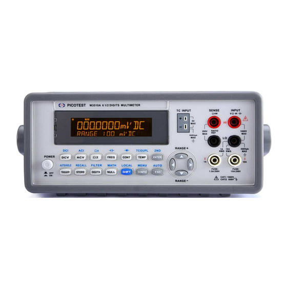
Note: Some following functions or instructions which the M3511A ※ doesn’t support or provide are colored green. 1.1 Feature Overview M3510A/11A is a 6 1/2 digits multimeter. It has… Best performance/price ratio High-speed sampling rate (50000 Rdgs/sec. at M3510A NPLC 0.001 & 10000 Rdgs/sec. at M3511A NPLC 0.006). - Page 6 High Storage Memory (Up to 2000 Readings) Free Application Software Note: The 1-year accuracy is subject to calibration accuracy. ※ In addition, the M3510A/11A provides wide ranges for general measurements, such as… DCV: 100mV, 1V, 10V, 100V & 1000V ACV: 100mV, 1V to 750V DCI: 10mA, 100mA, 1A, &...
-
Page 7: Warranty Information
No other warranty is expressed or implied, except for the above mentioned. The remedies provided herein are the buyer’s sole and exclusive remedies. PICOTEST shall not be liable for any direct, indirect, special, incidental or consequential damages. Limitation of warranty 1. -
Page 8: Precaution Of Operation
The rear protective conduct terminal needs to be connected to the actual earth ground or electric shock may occur. The patent and related documents for the equipment belong to PICOTEST CORP. and they aren’t allowed to be used by others without permission. 1.4 Upkeep of M3510A/11A Although M3510A/11A DMM is very durable and weather resistant, care should be taken not to expose it to severe impact or pressure. -
Page 9: Safety Information
Do not use the Meter around explosive gas or inflammable vapor. Wipe the surface of M3510A multimeter with a piece of dry and clean cloth. 1.5 Safety Information Caution! Please read through the following safety information before using the product. -
Page 10: Symbols And Terms
Note: Full M3510A/11A specifications are included in Appendix A. 1.7 Inspection Your product package is supplied with the following items: One M3510A/11A Multimeter unit. (88.8[H] x 214.6 [W] x 280.7 [D] mm, approx. 2.23 Kg) One power line cord. One USB cable. -
Page 11: Options And Accessories
Warning! If users use the Test Lead Set without following the specification of Picotest Corp., the protection of the Test Lead Set could be impaired. In addition, please don’t use a damaged Test Lead Set against the instrument break or personal injury. -
Page 12: The M3510A/11A's Dimension
M3500-opt10 K Type Thermocouple M3500-opt11 1.9 The M3510A/11A’s Dimension Please get the dimension’s information in the following different ways. 1. The dimension without the handle and the front & Rear Bumpers is in the following Picture 1. (LxWxD - 214.6x88.6x280.7 mm) 2. -
Page 13: Overview
M3510A/11A DMM. 2.1 Setting up M3510A/11A The purpose of this section is to prepare you for using M3510A DMM. You may want to check if you have all the parts with your multimeter. All our products are handled and inspected professionally before shipping out to our customers. - Page 14 Figure 1-1 S tep 2 ( Pull out the handle) 【 】 When the handle is turned up to 90° with the DMM please pull out the handle from the DMM as shown in Figure 1-2. Figure 1-2 . Adjusting the position for your convenience Ⅱ...
- Page 15 Figure 1-3 P osition 2 【 】 The position shown in Figure 1-4 is for operating the multimeter. Figure 1-4 P osition 3 【 】 The position shown in Figure 1-5 is for carrying the multimeter. Figure 1-5 15 15 15 15...
-
Page 16: To Connect The Power
Check the power-line voltage on the rear panel to see if voltage setting is correct for your area. There are 4 power lines, 100/120/220/240 on M3510A/11A for your demand. Change the voltage correctly or replace a new fuse if the voltage is not correct or the fuse is broken. Please follow the steps below. - Page 17 Figure 2-1 S tep 2 【 】 Press the latch to unlatch the voltage setting selector container as shown in Figure 2-2. (You may need a screwdriver to do so.) Figure 2-2 S tep 3 【 】 Remove the voltage setting selector container as shown in Figure 2-3. (You may need a screwdriver to do so.) 17 17 17 17...
- Page 18 Figure 2-3 S tep 4 【 】 Open the clips on the sides and remove the voltage setting selector from the container as shown in Figure 2-4. Figure 2-4 S tep 5 【 】 Turn the voltage setting selector so that the desired voltage setting appears in the container as shown in Figure 2-5.
-
Page 19: To Change The Fuse
Figure 2-5 S tep 6 【 】 Insert the voltage setting selector container back into the socket. 2.1.2.2 To change the fuse Warning! Before replacing the power-line fuse, make sure the multimeter is disconnected from the AC power. You must be qualified personnel to perform this action. - Page 20 Figure 2-6 S tep 2 【 】 Press the latch to unlatch the voltage setting selector container as shown in Figure 2-7. (You may need a screwdriver to do so.) Figure 2-7 S tep 3 【 】 Remove the voltage setting selector container as shown in Figure 2-8. (You may need a screwdriver to do so.) 20 20 20 20...
- Page 21 Figure 2-8 S tep 4 【 】 Remove the broken fuse from the container as shown in Figure 2-9. Figure 2-9 S tep 5 【 】 Replace with a new standard fuse. S tep 6 【 】 Insert the voltage setting selector container back into the socket. S tep 7 【...
- Page 22 Plug in your power cord as shown in Figure 2-11. Figure 2-11 S tep 9 【 】 Press the power switch on the front panel to turn on M3510A as shown in Figure 2-12. Figure 2-12 22 22 22 22...
-
Page 23: Factory Default When Power-On
2.1.3 Factory Default When Power-ON Table 2-1 shows the factory default of M3510A/11A. Table 2-1 Function Default Location after Power On Autozero Frequency and Period Source AC Voltage Output Format ASCII Ratio Frequency 20Hz AC Voltage AC Digits Range 10 V DC digits 6.5 (10 PLC) -
Page 24: M3510A/11A Function Introduction
2.2 M3510A/11A Function Introduction For you to become familiar with the M3510A/11A DMM, we will give a brief introduction to the basic operations. There are three major parts of M3510A/11A: (2.2.1) the front panel, (2.2.2) the display, and (2.2.3) the rear panel. We will discuss each of them in the following sections. - Page 25 CONT: Selects the continuity test. TEMP: Selects RTD temperature measurement. ENTER: Accepts selection, moving to next choice or back to measurement display. 2.2 First row with SHIFT button: DCI: Selects DC current measurement. ACI: Selects AC current measurement. Ω4: Selects 4-wire resistance measurement. : Selects capacitance measurement.
-
Page 26: The Display
(Maximum current: 3A, 250V and 15A, 250V) 2.2.2 The Display M3510A/11A has a dual-LCD-display for a better view. There are two rows in the dual-display screen. The upper row (Primary) displays readings and units. A maximum 11 characters are allowed for upper row LCD display. -
Page 27: Annunciators
RAT: Indicates the “RATIO” operation is taken. 2nd: Indicates 2ND function in use. 2.2.3 The Rear Panel The rear panel of the M3510A/11A is shown in Figure 2-20. This figure includes important abbreviated information that should be reviewed before using the instrument. - Page 28 6 6 6 6 5 5 5 5 1 1 1 1 2 2 2 2 3 3 3 3 4 4 4 4 Figure 2-20 1. VM COMP: Voltmeter Complete Output Terminal. Outputs a low-true pulse from a remote interface. 2.
-
Page 29: Basic Measurement Function
Basic Measurement Function This chapter introduces some basic measurement functions in M3510A/11A. You will learn how to use your M3510A/11A to measure voltage, current, resistance, frequency, period, continuity, diode and temperature in this chapter. 3.1 Voltage Measurements (DCV & ACV) The ranges for DC voltage measurements in M3510A/11A are 100mV, 1V, 10V, 100V and 1000V. -
Page 30: Current Measurements (Dc & Ac)
Note: RAT anunciator will lit when Ratio measurement is on. ※ 3.3 Current Measurements (DC & AC) The ranges for DC current measurements in M3510A/11A are 10mA, 100mA, 1A, and 10A. For AC current measurements, the range is 1A with sensitivity of 1 nA to 10A AC-Coupled TRMS with sensitivity of 10µA. -
Page 31: Resistance Measurements (2 & 4-Wire)
3A and 10A will be measured only through the 3A/10A and LO input connectors. Ensure the test leads are correctly connected to the DMM current inputs. It’s important to prevent the internal fuse damage from abusing source over 3 A on the 3 A input connector or over 10 A on the 10 Amp connector. -
Page 32: Frequency & Period Measurements
3.5 Frequency & Period Measurements M3510A/11A uses an on-board counter to measure the frequency/period. The measurement band is from 3Hz to 300KHz (or 333 ms to 3.3 µs) and the measurement voltages range from 100mV to 750V in AC. The range default setting is auto-range. -
Page 33: Continuity Measurements
“OVLD” will be displayed. 3.6 Continuity Measurements M3510A/11A uses 1 KΩ range for the continuity measurement. The meter beeps when the test resistance is less than the threshold resistance. The default threshold resistance is 10 , but you can set the threshold resistance to anything between 1 and 1 K . -
Page 34: Diode Measurements
3.7 Diode Measurements M3510A/11A uses a current source of 1 mA for diode testing. The maximum resolution is 10 µV on a fixed range of 1 V DC. The default threshold voltage is fixed between 0.3 and 0.8 volts and the reading rate is fixed at 0.2 PLC (The voltage bound is adjustable from 0.01V up to... -
Page 35: Temperature Measurements
3.8 Temperature Measurements M3510A supports thermocouples and resistance temperature detector (RTD) types of probes. For thermocouples, M3510A supports 9 types: B, C, E, J, K, N, R, S, and T. Please refer to Table 3-1 for their temperature ranges. Be sure that the temperature function is configured for the right sensor type before making measurements (Refer to 4.1.7 for how to... -
Page 36: Thermocouple Measurements
Temperature Temperature Sensor Type Range(°C) Range(°F) 600~1820 1112~3308 0~2316 32~4200.8 -250~1000 -418~1832 -250~400 -418~752 RTD (PT 100) -200~850 -328~1562 Note: Some following functions or instructions which the M3511A ※ doesn’t support or provide are colored green. 3.8.1 Thermocouple Measurements Connect the thermocouple sensor to the TC INPUT jack on the front panel. The difference between each type is subject to sensors. -
Page 37: Rtd Measurements
3.8.2 RTD Measurements There are three kinds of temperature measurements with RTDs: 2-wire, 3-wire and 4-wire measurements. You will find connection instructions and measuring procedures in the following sections. 3.8.2.1 2-Wire RTD Measurements How to measure temperature with 2-Wire RTD The following Figure 3-4 shows theory diagram of 2-Wire RTD measurement. -
Page 38: Support 3-Wire Rtd Measurements
Insert a specified adapter into the front terminals. Press TEMP button. Configure sensor type 4W RTD and unit by using the CONFIG button (refer to 4.1.7) or skip this step to use the default setting. Observe and take readings on the display. Figure 3-5 3.8.2.2.1 Support 3-Wire RTD Measurements How to measure temperature with 3-Wire RTD... -
Page 39: Capacitance Measurement
In Short Condition Figure 3-6 3.9 Capacitance Measurement The ranges for capacitance measurements in M3510A/11A are 1 nF, 10 nF, 100 nF, 1 µF, 10µF, 100µF, 1000µF and 10000µF. The default for “range” is auto-range. How to measure capacitance Connect the test leads to the terminals on the front panel. - Page 40 Table 3-1 (Available 2ND functions on M3510A) DCV DCI 2W 4W ACV ACI FREQ PER FREQ_C PER_C CAP TEMP TCO CONT DIODE Main FREQ FREQ_C PER_C TEMP CONT DIODE Table 3-2 (Available 2ND functions on M3511A) DCV DCI 2W 4W ACV ACI FREQ PER FREQ_C PER_C CAP TEMP TCO CONT DIODE...
- Page 41 PER_C TEMP CONT DIODE How to use 2ND measurement 1. Press one of the measurement function keys to select a primary measurement. 2. Press SHIFT+ENTER to enter 2ND submenu. 3. Use button to locate a desired secondary measurement, and ◁ o r ▷ press ENTER to select it.
- Page 42 [SENSe:]FUNCtion “<function>” For example: FUNCtion[1/2] “VOLTage:DC” FUNCtion[1/2] “VOLTage:AC” FUNCtion[1/2]”CURRent:DC” FUNCtion[1/2] “CURRent:AC” FUNCtion[1/2] “FREQunecy” FUNCtion[1/2] “FREQunecy:VOLT” FUNCtion[1/2] “PERiod” FUNCtion[1/2] “PERiod:VOLT” FUNCtion[1/2] “FREQunecy:CURR” FUNCtion[1/2] “PERiod:CURR” FUNCtion[1/2] “RESistance” FUNCtion[1/2] “FRESistance” FUNCtion[1/2] “CAPacitance” FUNCtion[1/2] “TEMPerature” FUNCtion[1/2] “TCOuple” FUNCtion[1/2] “NONE” FUNCtion[1/2]? When enabling the 2 function, you can still set the range and NPLC individually.
- Page 43 The following error codes might occur when corresponding function or range is not enabled or mismatch. -243:\"Second function invalid\ It means Secondary function is not enabled 223:\"2nd function mismatch\ It means function/2nd func mismatch. 225:\"Function/range mismatch\ It means function/range mismatch. 43 43 43 43...
-
Page 44: Front Panel Operations
Zero The purpose of Auto Zero function is to minimize the offset influence on your measurements. When Auto Zero is enabled, M3510A/11A takes the input signal reading as a base value and then internally disconnects the input signal, and takes an offset reading (a null offset). It then subtracts the offset from the base to get an accurate measurement. -
Page 45: Filter
However, Auto Zero ONCE issues an immediate offset measurement. 4.1.2 Filter Filter is used to remove noises in measurement readings. M3510A/11A is equipped with two types of filters: AC filter and digital filter. AC filter is for AC measurements only. -
Page 46: Ac Filter (Ac Only)
4.1.2.1 AC Filter (AC only) Definition: You can refer to Table 4-2 to set the bandwidth for selecting one of the three AC filters (Slow, Medium and Fast), in order to achieve either higher accuracy in low frequency measurements or faster AC settling time. -
Page 47: Digital Filter
DETector:BANDwidth {3|20|200|MIN|MAX} 4.1.2.2 Digital Filter Definition: M3510A/11A uses an averaging digital filter to yield a reading for display from a specified number of measurement readings in the past. The past measurement readings are stored in a stack of memory. The number may be in the range of 2 to 100. -
Page 48: Resolution & Nplc Setting
enabled. How to configure digital filter: You can configure the digital Filter either through the front panel operation or through the remote interface operation. Front Panel Operation For MODE setting: 1. Press SHIFT + DIGITS buttons and then use a nd b uttons to toggle ◁... - Page 49 PLC is suggested to select. However, the NPLC setting is used for DCV, DCI, Ω2 & Ω4 functions only. The lowest PLC on each digit range is the rapidest selection, such as 0.001 PLC at 4 1/2 digits, 0.2 PLC at 5 1/2 digits and 10 PLC at 6 1/2 digits.
-
Page 50: Threshold Resistance (Continuity)
Front Panel Operation First select your desired measurement function by pressing one of the function buttons located on the first row of your meter's front panel. Press DIGITS button to select a desired resolution for your measurement. Note: When following the Way One to set the resolution, your options ※... -
Page 51: Range (Manual & Auto)
4.1.5 Range (Manual & Auto) Definition When making measurements except CONT, DIODE, TCOUPL and Temperature, M3510A/11A will automatically choose a range for you, or you can select an appropriate range manually. The difference between auto-range and manual-range is the settling time. Auto-range is a convenient way for you, but manual-range can usually speed up the process. -
Page 52: Rate (Integration Time)
The unit of the integration time is in PLC (power line cycles). One PLC for 60 Hz is 16.67 ms, and for 50 Hz is 20 ms. There are 10 different integration times in M3510A/11A for you to select from: 0.001, 0.006, 0.02, 0.06, 0.2, 0.6, 1, 2, 10 and 100 PLCs. - Page 53 How to set the integration time: You can set the integration time either through the front panel operation or through the remote interface operation. Front Panel Operation Integration time is set indirectly when you select the measurement resolution. Please refer to 4.1.3 for details about how to set resolution or the digits.
-
Page 54: Sensor Selection For Temperature Measurements
4.1.7 Sensor Selection for Temperature Measurements The multimeter supports both thermocouple and RTD. User needs to configure the multimeter for the right sensor type before they can make temperature measurements. Definition If you are using RTD, the options are: PT100, D100, F100, PT385, PT3916, user-defined RTD, NTCT and SPRTD. - Page 55 In each subrange, the calibration constants required for that subrange are listed. Default The default sensor type in M3510A/11A is PT100. How to set up RTD You can set up the RTD configuration either through the front panel operation or through the remote interface operation.
- Page 56 in the calculation equation to obtain the temperature. Use ◁ ▷ move through the digits and to change the numbers to a △ ▽ desired value. Press ENTER to set the value. Choosing SPRTD takes you to a menu where you can specify the seven coefficients that are used to determine the temperature.
- Page 57 Thermocouple Definition M3510A is built-in cold junction compensation that can improve the accuracy of thermo measurements. If you are using this function, you have to set an adapter type. For example, through the “TYPE” selections you are available to use a specific adapter B, C, E, J, K, N, R, S or T for temperature measurement.
-
Page 58: Remote Interface Selection
SENSe: 4.1.8 Remote Interface Selection The M3510A/11A provides a standard USB and supports an optional GPIB/RS-232 interface, but only one interface can be activated at a time. If you are using GPIB, you must set the address for the multimeter. You... -
Page 59: Trigger Operations
ENTER to set the address. 4.2 Trigger Operations In this section we will discuss the triggering system in M3510A/11A. M3510A/11A provides a variety of trigger operations. You can select a trigger mode, a trigger source and different trigger settings for a specific measurement. -
Page 60: Trigger Mode
The rate of taking readings depends on the current settings. This function is only available through the front panel. The auto triggering is also the default for trigger mode in M3510A/11A. How to use Auto Trigger 1. Press SHIFT and TRIGGER on the front panel to enable auto trigger mode. -
Page 61: Trigger Source
Press TRIGGER key on the front panel to set the trigger mode. Disable the mode by pressing SHIFT + TRIGGER. 4.2.2 Trigger Source In M3510A/11A, you can specify the trigger source to be one of these three options: front panel operations, external hardware trigger source and remote interface operations. - Page 62 External Triger Terminal You can trigger the M3510A/11A by using a low-true pulse to the Ext Trig (external trigger) terminal located on the rear panel as shown in Figure 4-2. And to use this terminal via the remote interface, you have to select the external trigger source by using the TRIGer:SOURce EXTernal command.
-
Page 63: Trigger Setting
A. Number of samples on each trigger By default, M3510A/11A takes only one reading on each trigger, but you can instruct the multimeter to take specific number (up to 2000) of readings each time it receives a trigger. - Page 64 been turned off and the default value will be restored. You can set the number of samples on each trigger through front panel or the remote interface. Front Panel Operation Press SHIFT+CONFIG button. Set a defined parameter via the procedure TRIG SYS > TRIG CNT > ENTER.
- Page 65 Defaults The default of the trigger delay is automatic. M3510A/11A automatically selects a delay time for you according to the setting of the measurement if you do not specify a delay. A list of the default for each measurement function is shown on Table 4-5.
- Page 66 100Ω ~ 100kΩ 1.0 ms Ω2 and Ω4 1 MΩ 10 ms (PLC < 1) 10 MΩ ~ 100 MΩ 100 ms 3 Hz 7.0 s ACV/ACI 20 Hz 1.0 s (Remote Interface/ External Trigger/Single Trigger) 200 Hz 600 ms 3 Hz 1.5 s ACV/ACI...
-
Page 67: Math Operations
TRIGger:DELay {<seconds>|MINimum|MAXimum} TRIGger:DELay:AUTO {OFF|ON} 4.3 Math Operations This section will introduce the mathematical operations in M3510A/11A. There are eight math operations: PERCENT, AVERAGE, NULL, LIMITS (HIGH LIMIT/LOW LIMIT), MX+B, dB and dBm testing. They either store data for later use or perform mathematical operations on the readings. -
Page 68: Average (Avg/Min/Max/Count)
CALCulate:PERCent:TARGet? [MINimum|MAXimum] 4.3.2 Average (AVG/MIN/MAX/COUNT) Definition When the Average function is enabled, M3510A/11A takes in a series of readings from the measurements, stores the minimum and maximum readings in the memory, and then calculates the average value of all readings and reading counts. The number of readings taken since Average operation is enabled is recorded as well. -
Page 69: Null
Front Panel Operation Press one of the measurement function buttons to select a measurement function. Press SHIFT + NULL buttons to enter MATH submenu. buttons to locate “AVERAGE” submenu, and then ◁ ▷ press ENTER to actuate it. To read the average value, min/max value, total counts and readings counts, you can press buttons to switch ◁... -
Page 70: Limits Test
measurement, it is visible only for this measurement. How to operate the null (relative) function You can operate the null function from either the front panel operation or the remote interface operation. The Front Panel Operation 1. Store the null test lead resistance: First of all, short the two test leads together and then press NULL button. -
Page 71: Mx+B
a volatile memory. The default values for both upper and lower limits are “0”. This function is available to all except continuity and diode measurements. How to set the limits You can set the limits or make a limit testing either through the front panel or the remote interface operation. -
Page 72: Db/Dbm
answer (Y) will then be shown on the display according to the following equation. Y=MX+B This is especially useful when you need to do slope calculations on a series of measurements. The values of the “M” and “B” can be changed through the configuration of this function and they are stored in a volatile memory and will be cleared after the meter has been turned off or a remote interface reset. - Page 73 decibel unit in correspondence to a relative reference value. The calculation of dB is listed below: × log( Vref dB = (Input signal in dBm) – (relative value in dBm) NOTE: The is the input signal and the is the relative reference. ※...
- Page 74 Definition With dBm selected, a voltage measurement is displayed as the level of power, relative to 1 milliwatt, dissipated through a reference resistance. The reference resistance is adjustable in M3510A/11A. The calculation of dBm is defined as below: ...
-
Page 75: System Related Operations
CALCulate:STATe {OFF|ON} CALCulate:STATe? CALCulate:DBM:REFerence {<value>|MINimum|MAXimum} 4.4 System Related Operations In M3510A/11A, each system related operation performs a task that is not measurement related but plays an important role in making your measurements. 4.4.1 Display M3510A/11A has a dual-LCD-display screen. A maximum of 11... - Page 76 When the display is turned off, an “OFF” will be lit at right side of the display screen as shown in Figure 4-6. This doesn't mean the display is POWER-OFF, but only that the measurement readings will not be sent to the display.
-
Page 77: Beeper
(clears the message displayed) 4.4.2 Beeper M3510A/11A beeps when some certain conditions are met or when an error occurs. But there may be time you want to disable the beeper for some operations. Although you can turn off the beeper, the click sound you hear when a button is pressed will not be disabled. -
Page 78: Reading Memory (Store & Recall)
SYSTem:BEEPer:STATe {OFF|ON} 4.4.3 Reading Memory (Store & Recall) M3510A/11A has a memory capacity of 2000 readings. The readings are stored in first-in-first-out order and the memory type is volatile, which means the stored readings will be cleared when the multimeter is power-off. -
Page 79: Sensitivity Band (Hold)
4.4.4 Sensitivity Band (Hold) The reading hold function captures and holds a stable reading on the display. M3510A/11A beeps and holds the value when it detects a stable reading. The sensitivity band in reading hold decides which reading is stable enough. This band is expressed as a percent of reading on the selected range. -
Page 80: Initial Mode
You can select “SAVE DATA” to save the current settings which will exist after restarting next time. Or select “DEFAULT SET” to recall the factory value after restarting M3510A/11A. The SAVE DATA is available on using MEAS FUNC, RANGE, RESOLUTION, MATH FUNC & 2ND STATE. -
Page 81: Error Condition
ENTER to check the error message, such as “ERROR CODE” or “NO ERRORS”. 4.4.8 Firmware Revision M3510A/11A has three microprocessors for various internal systems. You can query the multimeter to determine which revision of firmware is 81 81 81 81... -
Page 82: Calibration
I/O processor and the third number is for the front-panel processor. 4.4.9 Calibration M3510A/11A will show the latest calibrated date and the next calibration date on the display after following the operation below. How to view the calibration information Do the procedure SHIFT + CONFIG >... - Page 83 How to execute Self-test This test procedure provides more tests for the hardware of M3510A/11A than the power-on tests. Do the procedure SHIFT + CONFIG > SYSTEM > ENTER > SELF TEST > ENTER to start the self-test. After self-test procedure, the result, PASS or FAIL, will be shown on the display.
- Page 84 the path SenseHi. 614 DC Path zero failed The reference point “Zero” is incorrect when getting readings through the path Input. 616 DC current sense failed The internal current is failed. 84 84 84 84...
-
Page 85: Remote Interface Operations
5.1 Pass/Fail Output From USB Connector The USB connector on the rear panel of M3510A/11A is a series “B” connector. When the USB interface is disabled (IEEE-488 interface is selected), the internal pass and fail TTL output signals (limit testing) will be transmitted via the USB port. -
Page 86: Setting Up For Remote Interface
USB or GPIB interface. How to set up for USB interface The USB cord should be connected well between M3510A/11A and your PC. Install the M3510A/11A application in your PC and execute the program. Click Tool tab for Command Control, then type in your command. -
Page 87: Remote Interface Commands
How to set up for GPIB interface Insert a GPIB interface card into the interface slot on the rear panel. Install the M3510A/11A application in your PC and execute the program. Click Tool tab for Command Control, then type in your command. - Page 88 MEASure: VOLTage:DC? {<range>|MIN|MAX|DEF},{<resolution>|MIN|MAX|DEF} VOLTage:DC:RATio? {<range>|MIN|MAX|DEF },{<resolution>|MIN|MAX|DEF} VOLTage:AC? {<range>|MIN|MAX|DEF},{<resolution>|MIN|MAX|DEF} CURRent:DC? {<range>|MIN|MAX|DEF},{<resolution>|MIN|MAX|DEF} CURRent:AC? {<range>|MIN|MAX|DEF},{<resolution>|MIN|MAX|DEF} RESistance? {<range>|MIN|MAX|DEF},{<resolution>|MIN|MAX|DEF} FRESistance? {<range>|MIN|MAX|DEF},{<resolution>|MIN|MAX|DEF} FREQuency? {<range>|MIN|MAX|DEF},{<resolution>|MIN|MAX|DEF} PERiod? {<range>|MIN|MAX|DEF},{<resolution>|MIN|MAX|DEF} CAPacitance? {<range>|MIN|MAX|DEF},{<resolution>|MIN|MAX|DEF} CONTinuity? DIODe? TCOuple TEMPerature? The CONFigure Command The CONFigure command offers a little more flexibility than the MEASure? Command.
- Page 89 TCOuple TEMPerature CONFigure? The READ? Command The READ? Command changes the state of the trigger system from the “idle” state to the “wait-for-trigger” state. When the specified trigger condition requirements are met after the multimeter receives the READ? command, the measurement will be initiated. The results are sent to the output buffer right away.
- Page 90 [SENSe:] FUNCtion “VOLTage:DC” FUNCtion “VOLTage:DC:RATio” FUNCtion “VOLTage:AC” FUNCtion “CURRent:DC” FUNCtion “CURRent:AC” FUNCtion “RESistance” (2-wire Ω) FUNCtion “FRESistance” (4-wire Ω) FUNCtion “FREQuency” FUNCtion “PERiod” FUNCtion “CAPacitance” FUNCtion “CONTinuity” FUNCtion “DIODe” FUNCtion “TCOuple” FUNCtion “TEMPerature” FUNCtion? [SENSe:] VOLTage:DC:RANGe {<range>|MINimum|MAXimum} VOLTage:DC:RANGe? [MINimum|MAXimum] VOLTage:AC:RANGe {<range>|MINimum|MAXimum} VOLTage:AC:RANGe? [MINimum|MAXimum] CURRent:DC:RANGe {<range>|MINimum|MAXimum} CURRent:DC:RANGe? [MINimum|MAXimum]...
- Page 91 [SENSe:] VOLTage:DC:RANGe:AUTO {OFF|ON} VOLTage:DC:RANGe:AUTO? VOLTage:AC:RANGe:AUTO {OFF|ON} VOLTage:AC:RANGe:AUTO? CURRent:DC:RANGe:AUTO {OFF|ON} CURRent:DC:RANGeAUTO? CURRent:AC:RANGe:AUTO {OFF|ON} CURRent:AC:RANGe:AUTO? RESistance:RANGe:AUTO {OFF|ON} RESistance:RANGe:AUTO? FRESistance:RANGe:AUTO {OFF|ON} FRESistance:RANGe:AUTO? FREQuency:VOLTage:RANGe:AUTO {OFF|ON} FREQuency:VOLTage:RANGe:AUTO? PERiod:VOLTage:RANGe:AUTO {OFF|ON} PERiod:VOLTage:RANGe:AUTO? CAPacitance:RANGe:AUTO {OFF|ON} CAPacitance:RANGe:AUTO? [SENSe:] VOLTage:DC:RESolution {<resolution>|MINimum|MAXimum} VOLTage:DC:RESolution? [MINimum|MAXimum] VOLTage:AC:RESolution {<resolution>|MINimum|MAXimum} VOLTage:AC:RESolution? [MINimum|MAXimum] CURRent:DC:RESolution {<resolution>|MINimum|MAXimum} CURRent:DC:RESolution? [MINimum|MAXimum] CURRent:AC:RESolution {<resolution>|MINimum|MAXimum} CURRent:AC:RESolutioin? [MINimum|MAXimum] RESistance:RESolution {<resolution>|MINimum|MAXimum}...
- Page 92 TCOuple:TYPE {E|J|K|N|R|S|T} TCOuple:TYPE? TCOuple:SIMulated {<value>|MINimum|MAXimum} TCOuple:SIMulated? [SENSe:] TEMPerature:RTD:TYPE {PT100|D100|F100|PT385|PT3916|USER|SPRTD|NTCT} TEMPerature:RTD:TYPE? TEMPerature:RTD:RZERo {<value>|MINimum|MAXimum} TEMPerature:RTD:RZERo? [MINimum|MAXimum] TEMPerature:RTD:ALPHa {<value>|MINimum|MAXimum} TEMPerature:RTD:ALPHa? [MINimum|MAXimum] TEMPerature:RTD:BETA {<value>|MINimum|MAXimum} TEMPerature:RTD:BETA? [MINimum|MAXimum] TEMPerature:RTD:DELTa {<value>|MINimum|MAXimum} TEMPerature:RTD:DELTa? [MINimum|MAXimum] TEMPerature:SPRTD:RZERo {<value>|MINimum|MAXimum} TEMPerature:SPRTD:RZERo? [MINimum|MAXimum] TEMPerature:SPRTD:A4 {<value>|MINimum|MAXimum} TEMPerature:SPRTD:A4? [MINimum|MAXimum] TEMPerature:SPRTD:B4 {<value>|MINimum|MAXimum} TEMPerature:SPRTD:B4? [MINimum|MAXimum] TEMPerature:SPRTD:AX {<value>|MINimum|MAXimum} TEMPerature:SPRTD:AX? [MINimum|MAXimum] TEMPerature:SPRTD:BX {<value>|MINimum|MAXimum} TEMPerature:SPRTD:BX? [MINimum|MAXimum]...
- Page 93 CURRent:DC:NPLCycles? [MINimum|MAXimum] RESistance:NPLCycles {0.001|0.006|0.02|0.06|0.2|0.6|1|2|10|100|MINimum|MAXimum} RESistance:NPLCycles? [MINimum|MAXimum] FRESistance:NPLCycles {0.001|0.006|0.02|0.06|0.2|0.6|1|2|10|100|MINimum|MAXimum} FRESistance:NPLCycles? [MINimum|MAXimum] [SENSe:] FREQuency:APERture {0.01|0.1|1|MINimum|MAXimum} FREQuency:APERture? [MINimum|MAXimum] PERiod:APERture {0.01|0.1|1|MINimum|MAXimum} PERiod:APERture? [MINimum|MAXimum] [SENSe:] DETector:BANDwidth {3|20|200|MINimum|MAXimum} DETector:BANDwidth? [MINimum|MAXimum] [SENSe:] AVERage:TCONtrol {MOVing|REPeat} AVERage:TCONtrol? AVERage:COUNt {<value>|MINimum|MAXimum} AVERage:COUNt? [MINimum|MAXimum] AVERage:STATe {OFF|ON} AVERage:STATe? [SENSe:] ZERO:AUTO {OFF|ONCE|ON} ZERO:AUTO? MATH OPERATION Commands There are eight math operations.
- Page 94 The math operations use one or more internal registers. You can preset the values in some of the registers, while others hold the results of the math operations. CALCulate: FUNCtion {PERCent|AVERage|NULL|LIMit|MXB|DB|DBM} FUNCtion? STATe {OFF|ON} STATe? CALCulate: PERCent:TARGet {<value>|MINimum|MAXimum} PERCent:TARGet? [MINimum|MAXimum] CALCulate: AVERage:MINimum? AVERage:MAXimum?
- Page 95 DATA:FEED RDG_STORE,{“CALCulate”|””} DATA:FEED? TRIGGERING M3510A/11A provides a variety of trigger operations. You User can select a trigger mode, a trigger source and different trigger settings for a specific measurement. Refer to Figure 4-8 for triggering system flow chart. Triggering from a remote interface is a multi-step sequence. You must first configure the mulitmeter by choosing the desired function, range and resolution.
- Page 96 SOURce? TRIGger: DELay {<seconds>|MINimum|MAXimum} DELay? [MINimum|MAXimum] TRIGger: DELay:AUTO {OFF|ON} DELay:AUTO? SAMPle: COUNt {<value>| MINimum|MAXimum } COUNt? [MINmum|MAXimum ] TRIGger: COUNt {<value>| MINimum|MAXimum|INFinite } COUNt? [MINmum|MAXimum] SYSTEM-RELATED Commands Each system related operation performs a task that is not measurement related but plays an important role in making your measurements. FETCh? READ? DISPlay {OFF|ON}...
- Page 97 SYSTem:VERSion? DATA:POINts? SYSTEM:IDNSTR “MANUFACTURER,PRODUCT” *RST *IDN? STATUS REPORTING Commands SYSTem:ERRor? STATus: QUEStionable:ENABle <enable value> QUEStionable:ENABle? QUEStionable:EVENt? STATus:PRESet *CLS *ESE <enable value> *ESE? *ESR? *OPC *OPC? *PSC {0|1} *PSC? *SRE <enable value> *SRE? *STB? Other Interface Commands SYSTem:LOCal SYSTem:REMote 97 97 97 97...
- Page 98 IEEE-488.2 COMMON Commands *CLS *ESE <enable value> *ESE? *ESR? *IDN? *OPC *OPC? *PSC {0|1} *PSC? *RST *SRE <enable value> *SRE? *STB? *TRG 98 98 98 98...
-
Page 99: Error Messages
Errors are retrieved in first-in-first-out (FIFO) order. The first error returned is the first error that was stored. When user has read all errors from the queue, the ERROR annunciator turns off. M3510A/11A beeps once each time an error occurs. - Page 100 -104 Data type error A parameter type error was found in the command string. -105 GET not allowed A Group Execute Trigger (GET) is not allowed in the command string. -108 Parameter not allowed More parameters were found than needed for the command . -109 Missing parameter Not enough parameters were received for the command.
- Page 101 A discrete parameter was received but a character string or a numeric parameter was expected. -151 Invalid string data An invalid character string was received. -158 String data not allowed A character string was received but not allowed for the command. -160~-168 Block data errors Block data is not acceptable.
- Page 102 -222 Data out of range A numeric parameter value is out of range. -223 Too much data A character string was too long. -224 Illegal parameter value A discrete parameter was received which was not a valid choice for the command.
- Page 103 521 Input buffer overflow 522 Output buffer overflow 531 Insufficient memory There is not enough memory to store the requested number of readings in internal memory using the INITiate command. The product of the sample count (SAMPle:COUNt) and the trigger count (TRIGger:COUNt) must not exceed 2000 readings.
- Page 104 651 Panel Program Checksum Error The checksum from the panel is incorrect.
-
Page 105: Appendix
M3510A/11A. It covers the AC, DC, Resistance, Temperature, and Frequency/Period characteristics under a variety of conditions. It also contains the general characteristics and accuracy calculations for your convenience. A lot of efforts are made to make sure these specifications serve your needs for production, engineering and/or research purposes. - Page 106 10.00000 KΩ 10 mΩ 0.020+0.002 100.0000 KΩ 100 mΩ 0.020+0.002 1.000000 MΩ 1 Ω 0.020+0.004 10.00000 MΩ 10 Ω 0.100+0.004 100.0000 MΩ 100 Ω 1.500+0.005 DIODE 1.00000 V 10 µV 0.020+0.020 CONTINUITY 1000.00 Ω 10 mΩ 0.020+0.030 (for 2WΩ) FREQUENCY & PERIOD Frequency Function Range...
- Page 107 (TRMS) 1K-5K 1.00+0.100 10-1K 0.300+0.060 3.00000 A 10 µA 1K-5K 1.500+0.150 10-1K 0.500+0.120 10.00000 A 10 µA 1K-5K 2.50+0.20 CAPACITANCE CHARACTERISTICS Test Function Range 1 Year Accuracy Current 1 nF 10 µA 2.0+0.80 10 nF 10 µA 1.0+0.50 100 nF 100 µA 1.0+0.50 1 µF...
-
Page 108: General Specifications
B. General Specifications item Limitation & description 100V/120V/220V/240V Power Supply ± Power Line 50/60 Hz ± Frequency Power Consumption 25 VA peak (5 W AVERAGE) Operating to 50 ℃ ℃ Temperature Maximum relative humidity 80% for temperature up to 31 . -
Page 109: Remote Interface Reference
C. Remote Interface Reference C.1 An Introduction to the SCPI Language SCPI (Standard Commands for Programmable Instruments) is an ASCII-based instrument command language designed for test and measurement instruments. Refer “Simplified Programming Overview,” for an introduction to the basic techniques used to program the multimeter over the remote interface. - Page 110 keywords. A colon ( : ) separates a command keyword from a lower-level keyword. Command Format Used in This Manual The format used to show commands in this manual is shown below: VOLTage:DC:RANGe {<range>|MINimum|MAXimum} The command syntax shows most commands (and some parameters) as a mixture of upper- and lower-case letters.
- Page 111 Querying Parameter Settings You can query the current value of most parameters by adding a question mark ( ? ) to the command. For example, the following command sets the sample count to 10 readings: "SAMP:COUN 10" You can query the sample count by executing: "SAMP:COUN?"...
- Page 112 "*RST; *CLS; *ESE 32; *OPC?" SCPI Parameter Types The SCPI language defines several different data formats to be used in program messages and response messages. Numeric Parameters Commands that require numeric parameters will accept all commonly used decimal representations of numbers including optional signs, decimal points, and scientific notation.
-
Page 113: Output Data Formats
String Parameters String parameters can contain virtually any set of ASCII characters. A string must begin and end with matching quotes; either with a single quote or with a double quote. You can include the quote delimiter as part of the string by typing it twice without any characters in between. The following command uses a string parameter: DISPlay:TEXT <quoted string>... - Page 114 MEASure:VOLTage:DC:RATio? {<range>|MIN|MAX|DEF },{<resolution>|MIN|MAX|DEF} Preset and make a dc:dc ratio measurement with the specified range and resolution. The reading is sent to the output buffer. For ratio measurements, the specified range applies to input signal, yet autorange is selected for the reference signal.
-
Page 115: The Configure Command
MEASure:PERiod? {<range>|MIN|MAX|DEF},{<resolution>|MIN|MAX|DEF} Preset and make a period measurement with the specified range and resolution. The reading is sent to the output buffer. For period measurements, the meter uses only one “range” for all inputs between 0.33 seconds and 3.3 s ec. With μ... - Page 116 CONFigure:VOLTage:DC:RATio {<range>|MIN|MAX|DEF },{<resolution>|MIN|MAX|DEF} Preset and configure the multimeter for DC:DC ratio measurements with the specified range and resolution. This command does not initiate the measurement. The specified range applies to the source signal and autorange is selected for the reference signal. CONFigure:VOLTage:AC {<range>|MIN|MAX|DEF},{<resolution>|MIN|MAX|DEF} Preset and configure the multimeter for AC voltage measurements with the specified range and resolution.
-
Page 117: The Measurement Configuration Command
frequency measurements return “0”. CONFigure:PERiod {<range>|MIN|MAX|DEF},{<resolution>|MIN|MAX|DEF} Preset and configure a period measurement with the specified range and resolution. This command does not initiate the measurement. For period measurements, the meter uses only one “range” for all inputs between 0.33 seconds and 3.3 sec. With no input signal applied, period measurements return “0”. CONFigure:CAPacitance {<range>|MIN|MAX|DEF},{<resolution>|MIN|MAX|DEF} Preset and configure the multimeter for capacitance measurements with the specified range and resolution. - Page 118 Select a measurement function and enclose it in quotes in the command string (FUNC “VOLT:DC”). Use one of the following strings. VOLTage:DC VOLTage:AC VOLTage:DC:RATio CURRent:DC CURRent:AC CAPacitance RESistance (for 2-wire ohms) FRESistance (for 4-wire ohms) FREQuency PERiod CONTinuity DIODe TCOuple TEMPerature [SENSe:]FUNCtion? Query the measurement function and return a quoted string.
- Page 119 [SENSe:]<function>:RANGe {<range>|MINimum|MAXimum} Select a range for the selected function. For frequency and period measurements, range applies signal’s input voltage, frequency (use FREQuency:VOLTage or PERiod:VOLTage). MIN selects the lowest range for the selected function. MAX selects the highest range. [SENSe:]<function>:RANGe? [MINimum|MAXimum] Query the range for the selected function.
- Page 120 [SENSe:]TCOuple:TYPE? Query thermocouple sensor type. [SENSe:]TCOuple:RJUNction:RSELect {REAL|SIMulated } Select a reference junction type, real or simulated. [SENSe:]TCOuple:RJUNction:RSELect? Query the reference junction type, real or simulated. [SENSe:]TCOuple:RJUNction:SIMulated {<value>|MINimum|MAXimum} Set the default temperature of the simulated reference junction. [SENSe:]TCOuple:RJUNction:SIMulated? Query the default temperature of the simulated reference junction. [SENSe:]TCOuple:RJUNction:REAL:OFFSet {<value>|MINimum|MAXimum} Set the offset voltage of the real reference junction.
- Page 121 [SENSe:]TEMPerature:RTD:ALPHa? [MINimum|MAXimum] Query the alpha constant for the user type. [SENSe:]TEMPerature:RTD:BETA {<value>|MINimum|MAXimum} Set the beta constant for the user type. [SENSe:]TEMPerature:RTD:BETA? [MINimum|MAXimum] Query the beta constant for the user type. [SENSe:]TEMPerature:RTD:DELTa {<value>|MINimum|MAXimum} Set the delta constant for the user type. [SENSe:]TEMPerature:RTD:DELTa? [MINimum|MAXimum] Query the delta constant for the user type.
- Page 122 [SENSe:]TEMPerature:SPRTD:AX? [MINimum|MAXimum] Query the A coefficient. [SENSe:]TEMPerature:SPRTD:BX {<value>|MINimum|MAXimum} Set the B coefficient. [SENSe:]TEMPerature:SPRTD:BX? [MINimum|MAXimum] Query the B coefficient. [SENSe:]TEMPerature:SPRTD:CX {<value>|MINimum|MAXimum} Set the C coefficient. [SENSe:]TEMPerature:SPRTD:CX? [MINimum|MAXimum] Query the C coefficient. [SENSe:]TEMPerature:SPRTD:DX {<value>|MINimum|MAXimum} Set the D coefficient. [SENSe:]TEMPerature:SPRTD:DX? [MINimum|MAXimum] Query the D coefficient. [SENSe:]TEMPerature:TRANsducer FRTD Set the RTD Measurement to 4-Wire.
-
Page 123: The Math Operation Command
[SENSe:]PERiod:APERture{0.01|0.1|1|MINimum|MAXimum} Set the gate time (or aperture time) for period function. Specify 10 ms (4.5 digits), 100 ms (default; 5.5 digits), or 1 second (6.5 digits). [SENSe:]PERiod:APERture? [MINimum|MAXimum] Query the gate time (or aperture time) for period function. [SENSe:]DETector:BANDwidth {3|20|200|MINimum|MAXimum} Specify the lowest frequency expected in the input signal. - Page 124 CALCulate:STATe? Query the state of the math function. Returns “0”(OFF) or “1”(ON). CALCulate:PERCent:TARGet {<value>|MINimum|MAXimum} Set the target value for percent math function. The multimeter clears the value when Min/Max is turned on, when the power has been off or a remote interface reset.
- Page 125 CALCulate:LIMit:LOWer {<value>|MINimum|MAXimum} Set the lower limit for limit testing. You can set the value to any number from 0 ± 120% of the highest range, for the present function. CALCulate:LIMit:LOWer? Query the lower limit for the limit testing. CALCulate:LIMit:UPPer {<value>|MINimum|MAXimum} Set the upper limit for limit testing.
-
Page 126: The Triggering Commands
CALCulate:DBM:REFerence? [MINimum|MAXimium] Query the dBm reference value. DATA:FEED RDG_STORE,{“CALCulate”|””} Selects whether readings taken using the INITiate command are stored in the multimeter’s internal memory (default) or not stored at all. In the default state (DATA:FEED RDG_STORE,“CALC”), up to 2000 readings are stored in memory when INITiate is executed. - Page 127 TRIGger:SOURce? Query the trigger source. TRIGger:DELay {<seconds>|MINimum|MAXimum} Set a trigger delay time in seconds. The delay is the time between the trigger signal and each sample that follows. Specify a delay time from 0 to 3600 seconds. TRIGger:DELay? Query the trigger delay time. TRIGger:DELay:AUTO {OFF|ON} Disable or enable a automatic trigger delay.
-
Page 128: The System-Related Commands
C.8 The System-Related Commands FETCh? Transfer readings stored in memory by the INITiate command to output buffer where you are able to read them into your bus controller. READ? Change the state of the triggering system from the “idle” state to “wait-for-trigger”... - Page 129 SYSTem:ERRor? Query the multimeter’s error queue. Up to 20 errors can be stored in the queue. Errors are retrieved in first-in-first-out (FIFO) order. Each error string may contain up to 80 characters. SYSTem:VERSion? Query the present SCPI version. Set to the default identification string. Set to the compatible identification string.
-
Page 130: The Scpi Status Pattern
the LOCAL button, are disabled. C.9 The SCPI Status Pattern Status registers are provided in the same way by all SCPI equipment. And there are three register groups with various equipment conditions recorded by the status system. They are the Status Byte Register, the Standard Event Register and the Questionable Data Register. - Page 131 Binary Weights 2º = 1 = 256 2¹ = 2 = 512 2² = 4 = 1024 2³ = 8 = 2048 = 16 = 4096 = 32 = 8192 = 16384 = 64 = 32768 = 128 About the Status Byte The conditions from other status registers will be reported by the status byte summary register.
- Page 132 in bit 4. Besides, bits are not latched in the summary registers. In addition, to clear an event register will clear the according bits in the status byte summary register. And to read all messages in the output buffer, including all pending queries, will clear the message available bit. The following list shows the definition of each bit.
- Page 133 to select the low-level IEEE-488 SRQ signal set by summary bits. As the status byte bit 6 is set, an IEEE-488 SRQ interrupt message will be sent automatically to the bus controller which may poll the instruments on the bus to identify which one requested service. To read the status byte which is using an IEEE-488 serial poll or to read the event register, whose summary bit is cauing the service request, will clear the request service.
- Page 134 synchronization. Enable the bus controller’s IEEE-488 SRQ interrupt. Procedures to Determine When a Command Sequence is Completed. Clear the DMM’s output buffer by sending a device clear message. Clear the event registers by using *CLS command. Enable “operation complete” by using the *ESE 1 command. Send the *OPC? command and enter the result to enable synchronization.
- Page 135 About the Standard Event Register The standard event register reports the instrument event types below, such as power-on detected, command syntax errors, command execution errors, self-test (calibration errors), query errors or the moment of executing an *OPC command. Then through the enable register, all conditions will be reported in the standard event summary bit.
- Page 136 The following conditions will clear the standard event register. Users send a *CLS command. Users query the event register by using the *ESR? command. The following conditions will clear the standard event enable register. Users turn on the power, and have set the DMM previously by using the *PSC 1 command.
-
Page 137: Status Reporting Commands
Range overload on 2-/4-wired ohm function. Ohms Overload 1024 Set to 0 Not Used Reading is less than lower limit under limit test. 2048 Limit Failed at LO 4096 Reading is excess upper limit under limit test. Limit Failed at HI 8192 Set to 0 Not Used... - Page 138 decimal value which corresponds to the binary-weighted sum of all bits set in the register. STATus:PRESet Clear all bits in the Questionable Data enable register. *CLS Clear the Status Byte summary register and all event registers. *ESE <enable value> Enable bits in the Standard Event enable register. The selected bits are then reported to the Status Byte.
-
Page 139: Scpi Compliance Information
C.11 SCPI Compliance Information This section encloses a list of commands that are device-specific to the M3510A/11A. Although not included in the 1999.0 version of the SCPI standard, these commands are compliant to the SCPI format and they follow the syntax rules of the standard. - Page 140 FUNCtion "DIODe" FREQuency:VOLTage:RANGe {<range>|MINimum|MAXimum} FREQuency:VOLTage:RANGe? [MINimum|MAXimum] FREQuency:VOLTage:RANGe:AUTO {OFF|ON} FREQuency:VOLTage:RANGe:AUTO? PERiod:VOLTage:RANGe {<range>|MINimum|MAXimum} PERiod:VOLTage:RANGe? [MINimum|MAXimum] PERiod:VOLTage:RANGe:AUTO {OFF|ON} PERiod:VOLTage:RANGe:AUTO? ZERO:AUTO? CALCulate: PERCent:TARGet {<value>|MINimum|MAXimum} PERCent:TARGet? [MINimum|MAXimum] AVERage:MINimum? AVERage:MAXimum? AVERage:AVERage? AVERage:COUNt? NULL:OFFSet {<value>|MINimum|MAXimum} NULL:OFFSet? [MINimum|MAXimum] LIMit:LOWer {<value>|MINimum|MAXimum} LIMit:LOWer? [MINimum|MAXimum] LIMit:UPPer {<value>|MINimum|MAXimum} LIMit:UPPer? [MINimum|MAXimum] MXB:MMFactor {<value>|MINimum|MAXimum} MXB:MMFactor? [MINimum|MAXimum] MXB:MBFactor {<value>|MINimum|MAXimum} MXB:MBFactor? [MINimum|MAXimum]...
-
Page 141: Ieee-488 Compliance Information
INPut: IMPedance:AUTO {OFF|ON} IMPedance:AUTO? C.12 IEEE-488 Compliance Information IEEE-488.2 Common Commands *CLS *ESE <enable value> *ESE? *ESR? *IDN? *OPC *OPC? *PSC {0|1} *PSC? *RST *SRE <enable value> *SRE? *STB? *TRG Dedicated Hardware Lines Addressed Commands Attention Interface Clear Remote Enable Service Request Interrupt... - Page 142 Device Clear End or Identify Message Terminator Group Execute Trigger Go to Local Local Lock-Out Selected Device Clear Serial Poll Disable Serial Poll Enable Using Device Clear to Halt Measurements Device clear is an IEEE-488 low-level bus message which can be used to halt measurements in progress.
-
Page 143: About Application Programs
Visual Basic: Explore the Samples. Visual C++ In an MFC application, you can override PICOTEST IOUtils interfaces in a class as well as provide additional interfaces. The example in this article illustrates how to override an interface in a class while preserving the original interface implementation so that it can be delegated to by the new interface implementation. - Page 144 3. Add New Module, and declare a Sub Main(). How to: Change the Startup Object for an Application The Startup Object property for a project defines the entry point to be called when the application loads; generally this is set to either the main form in your application or to the Sub Main procedure that should run when the application starts.
- Page 145 Dim sesn As ViSession Dim fList As ViFindList Dim desc As String * VI_FIND_BUFLEN Dim nList As Long Dim ret As Long Dim readin As String * 64 stat = viOpenDefaultRM(dfltRM) If (stat < VI_SUCCESS) Then 'Rem Error initializing VISA ... exiting MsgBox "USBTMC resource not found.", vbExclamation, "M3510 multimeter device test"...
- Page 146 MsgBox "System command error. (*RST)", vbExclamation, "M3510 multimeter device test" stat = viClose(fList) Exit Sub End If Rem send Clear command '*CLS'-- Clear M3510 status register stat = viWrite(sesn, "*CLS", 4, ret) If (stat < VI_SUCCESS) Then MsgBox "System command error. (*CLS)", vbExclamation, "M3510 multimeter device test"...
- Page 147 MsgBox "System command error. (system:local)", vbExclamation, "M3510 multimeter device test" stat = viClose(fList) Exit Sub End If stat = viClose(sesn) stat = viClose(fList) stat = viClose(dfltRM) MsgBox "End of Job." End Sub Using CONFigure with a Math Operation The following example uses CONFigure with the dBm math operation. The CONFigure command gives you a little more programming flexibility than the MEASure? command.
- Page 148 ######################################### Dim stat As ViStatus Dim dfltRM As ViSession Dim sesn As ViSession Dim fList As ViFindList Dim desc As String * VI_FIND_BUFLEN Dim nList As Long Dim ret As Long Dim readin As String * 128 Dim i As Integer ' Array index stat = viOpenDefaultRM(dfltRM) If (stat <...
- Page 149 If (stat < VI_SUCCESS) Then MsgBox "System command error.", vbExclamation, "M3510 multimeter device test" stat = viClose(fList) Exit Sub End If Rem send command -- Set kM3510 to 1 amp ac range stat = viWrite(sesn, "CONF:VOLT:AC 1,0.001", 20, ret) If (stat < VI_SUCCESS) Then MsgBox "System command...
- Page 150 C++ DEVQUERY Sample Application This C sample application is a Win32 console application. It illustrates how to use the PICOTEST IOUtils COM. A Win32 console application is a Win32 application which uses text-based input and output, not a graphical interface.
- Page 151 LISTING C.3. THE DEVQUERY FUNCTION. // devquery.cpp : Defines the entry point for the console application. // Call the NI-VISA library visa32.dll #include "stdafx.h" #include "visa.h" //standard include for a Microsoft Visual C++ project #include "stdio.h" #include "windows.h" void main(int argc, char* argv[]) // TODO: Add your control notification handler code here HINSTANCE hUSBTMCLIB;...
- Page 152 MessageBox(NULL, "NIVISA for USBTMC library not found.", "M3510 multimeter device test", MB_OK); return; // Link the libraries signed long (__stdcall *PviOpenDefaultRM_usb) (unsigned long *vi); signed long (__stdcall *PviFindRsrc_usb) (unsigned long sesn, char *expr, unsigned long *vi, unsigned long *retCnt, char far desc[]); signed long (__stdcall *PviOpen_usb) (unsigned long sesn, char *name, unsigned long mode,...
- Page 153 PviOpen_usb = (signed long (__stdcall*)(unsigned long, char*, unsigned long, unsigned long, unsigned long*))GetProcAddress(hUSBTMCLIB, (LPCSTR)"viOpen"); PviWrite_usb = (signed long (__stdcall*)(unsigned long, unsigned char*, unsigned long, unsigned long*))GetProcAddress(hUSBTMCLIB, (LPCSTR)"viWrite"); PviRead_usb = (signed long (__stdcall*)(unsigned long, unsigned char*, unsigned long, unsigned long*))GetProcAddress(hUSBTMCLIB, (LPCSTR)"viRead"); PviSetAttribute_usb = (signed long (__stdcall*)(unsigned long, unsigned long, unsigned long))GetProcAddress(hUSBTMCLIB, (LPCSTR)"viSetAttribute");...
- Page 154 if (status < 0L) PviClose_usb(m_defaultRM_usbtmc); hUSBTMCLIB = NULL; m_defaultRM_usbtmc = 0; MessageBox(NULL, "USBTMC resource found.", "M3510 multimeter device test", MB_OK); return; else // Find the USBTMC device USB[0-9]*::0x05E6::0xM3510::?*INSTR ( Hex ) status PviFindRsrc_usb (m_defaultRM_usbtmc, "USB[0-9]*::0x05E6::0xM3510::?*INSTR", &m_findList_usbtmc, &m_nCount, instrDescriptor); if (status < 0L) Find USBTMC device...
- Page 155 else PviOpen_usb(m_defaultRM_usbtmc, instrDescriptor, &m_instr_usbtmc); status PviSetAttribute_usb(m_instr_usbtmc, VI_ATTR_TMO_VALUE, m_Timeout); if (!hUSBTMCLIB) printf("M3510 device connect failed.\n"); return; // Write command "*IDN?" and read the M3510 identification string len = 64; pStrout = new char[len]; ZeroMemory(pStrout, len); strcpy(pStrout, "*idn?"); status = PviWrite_usb(m_instr_usbtmc, (unsigned char *)pStrout, 6, &nWritten);...
- Page 156 // Read data from device len = 64; if (hUSBTMCLIB) status = PviRead_usb(m_instr_usbtmc, pStrin, len, &nRead); if (nRead > 0) for (len=0; len < (long) nRead; len++) buffer[len] = pStrin[len]; buffer[nRead] = '\0'; printf(" input : %s\n\n",buffer); // Set sample count to 1 strcpy(pStrout, "SAMP:COUN 1");...
- Page 157 &nWritten); Sleep(3000); // Fetch the M3510 measure value ( screen value ) // Set Voltage DC measure strcpy(pStrout, "CONF:VOLT:DC 0.1,0.1"); status = PviWrite_usb(m_instr_usbtmc, (unsigned char *)pStrout, 21, &nWritten); Sleep(1000); // Send read command strcpy(pStrout, "READ?"); status = PviWrite_usb(m_instr_usbtmc, (unsigned char *)pStrout, 6, &nWritten);...
- Page 158 m_nCount = 0; m_defaultRM_usbtmc = 0; FreeLibrary (hUSBTMCLIB); hUSBTMCLIB = NULL; return;...
- Page 159 2006/95/EC and the EMC Directive 2004/108/EC and goes with the CE Marking accordingly. Conformity with the following product standards: Manufacturer Name: Picotest Corp. Manufacturer Address: 5F-1, 286-9, Hsin-Ya Rd, 80673, Kaohsiung, Taiwan Declaration of Product Product Name: 6 1/2 Digit Digital Multimeter...
Need help?
Do you have a question about the M3510A and is the answer not in the manual?
Questions and answers