Sign In
Upload
Manuals
Brands
HEIDENHAIN Manuals
Controller
MANUALPLUS 620
HEIDENHAIN MANUALPLUS 620 Manuals
Manuals and User Guides for HEIDENHAIN MANUALPLUS 620. We have
5
HEIDENHAIN MANUALPLUS 620 manuals available for free PDF download: Technical Manual, User Manual, Manual
HEIDENHAIN MANUALPLUS 620 Technical Manual (1818 pages)
Brand:
HEIDENHAIN
| Category:
Control Systems
| Size: 32.13 MB
Advertisement
HEIDENHAIN MANUALPLUS 620 User Manual (697 pages)
smart.Turn and DIN Programming
Brand:
HEIDENHAIN
| Category:
Control Systems
| Size: 26.54 MB
Table of Contents
See User's Manual
8
Introduced, See User's Manual
9
See User's Manual
10
In Simulation Submode, the Dimensioning Function was
12
See User's Manual
14
See User's Manual
15
See User's Manual
16
Table of Contents
17
NC Programming
41
Smart.turn and DIN/ISO Programming
42
Contour Follow-Up
42
Structured NC Program
43
Linear and Rotary Axes
45
Units of Measure
45
Elements of the NC Program
46
Fundamentals: Smart.turn Editor
47
Menu Structure
47
Parallel Editing
48
Screen Layout
48
Selecting the Editor Functions
49
Editing with Active Tree View
50
Shared Menu Items
51
Program Section Code
58
PROGRAM HEAD Section
60
CHUCKING EQUIPMENT Section
62
TURRET / MAGAZINE Section
63
Contour Group Section
64
BLANK Section
64
FINISHED PART Section
64
AUX. BLANK Section
64
TEMPORARY Section
64
FRONT / REAR SIDE Section
65
LATERAL Section
65
FRONT y / REAR SIDE y Section
65
SURFACE y Section
66
MACHINING Section
68
END Code
68
SUBROUTINE Section
68
Return Code
68
CONST Code
68
VAR Code
69
Tool Programming
70
Setting up a Turret List
70
Editing Tool Entries
72
Multipoint Tools
72
Replacement Tools
73
Automatic Job
74
Smart.turn Units
77
Smart.turn Unit
78
Units - Smart.turn Units
78
Units Menu Item
78
Longitudinal Roughing in ICP Unit
86
Units - Roughing
86
Transverse Roughing in ICP Unit
88
Contour-Parallel Roughing in ICP Unit
90
Bidirectional Roughing in ICP Unit
92
Longitudinal Roughing with Direct Contour Input Unit
94
Transverse Roughing with Direct Contour Input Unit
95
ICP Contour Recessing Unit
96
Units - Recessing
96
ICP Recess Turning Unit
98
Contour Recessing with Direct Contour Input Unit
100
Recess Turning with Direct Contour Input Unit
101
Parting Unit
102
Undercutting Form H, K, U Unit
103
ICP Recessing Unit
104
Centric Drilling Unit
105
Units - Centric Drilling
105
Centric Tapping Unit
107
Centric Boring/Countersinking Unit
109
Single Hole, Face Unit
110
Units - Drilling in C Axis
110
Linear Pattern Drilling, Face Unit
112
Circular Pattern Drilling, Face Unit
114
Tap Hole, Face Unit
116
Linear Tapping Pattern, Face Unit
117
Circular Tapping Pattern, Face Unit
118
Single Hole, Lateral Surface Unit
119
Linear Pattern Drilling, Lateral Surface Unit
121
Circular Pattern Drilling, Lateral Surface Unit
123
Tap Hole, Lateral Surface Unit
125
Linear Tapping Pattern, Lateral Surface Unit
126
Circular Tapping Pattern, Lateral Surface Unit
127
ICP Drilling, C Axis Unit
129
ICP Tapping, C Axis Unit
131
ICP Boring/Countersinking, C Axis Unit
132
ICP Bore Milling, C Axis Unit
133
Predrilling, Contour Milling, Figures Unit
137
Predrilling, Contour Milling, Figures, Lateral Surface Unit
143
Contour Milling, Figures, Face Unit
174
Pocket Milling, Figures, Face Unit
176
Engraving, Face Unit
178
ICP Contour Milling, Face Unit
179
ICP Pocket Milling, Face Unit
180
Deburring, Face Unit
181
ICP Face Milling Unit
182
Slot, Lateral Surface Unit
183
Units - Milling, Lateral Surface (C Axis)
183
Linear Slot Pattern, Lateral Surface Unit
184
Circular Slot Pattern, Lateral Surface Unit
185
Contour Milling, Figures, Lateral Surface Unit
187
Pocket Milling, Figures, Lateral Surface Unit
189
Engraving, Lateral Surface Unit
191
ICP Contour Milling, Lateral Surface Unit
192
ICP Pocket Milling, Lateral Surface Unit
193
Deburring, Lateral Surface Unit
194
2.11 Units - Special Operations
195
Program Beginning Unit
195
C Axis off Unit
197
C Axis on Unit
197
Subprogram Call Unit
198
Program Section Repeat Unit
199
Program End Unit
200
Tilt Plane Unit
201
Predrilling, Pocket Milling, Figures, Lateral Surface Unit
145
Predrilling, Contour Milling, ICP, Lateral Surface Unit
147
Predrilling, Pocket Milling, ICP, Lateral Surface Unit
149
ICP Contour Machining - ICP Finishing Unit
150
Units - Finishing
150
Contour Machining, Direct Longitudinal - Finishing Longitudinal with Direct Contour Input Unit
153
Contour Machining, Direct Transverse - Finishing Transverse with Direct Contour Input Unit
155
Undercut Form E, F , DIN76 Unit
157
Measuring Cut Unit
159
Handwheel Superimposition
160
Overview of Thread Units
160
Units - Threads
160
Parameter V: Type of Infeed
161
Thread, Direct Unit
162
ICP Thread Unit
164
API Thread Unit
166
Tapered Thread Unit
167
Slot, Face Unit
169
Units - Milling, Face (C Axis)
169
Linear Slot Pattern, Face Unit
170
Circular Slot Pattern, Face Unit
171
Face Milling Unit
172
Thread Milling Unit
173
Units - Predrilling in C Axis
137
Predrilling, Pocket Milling, Figures, Face Unit
139
Predrilling, Contour Milling, ICP, Face Unit
141
Predrilling, Pocket Milling, ICP, Face Unit
142
Smart.turn Units for the y Axis
203
Units - Drilling in y Axis
204
ICP Drilling, y Axis Unit
204
ICP Tapping, y Axis Unit
205
ICP Boring/Countersinking, y Axis Unit
206
ICP Bore Milling, y Axis Units
207
Units - Predrilling in y Axis
211
ICP Predrilling, Contour Milling, XY Plane Unit
211
ICP Predrilling, Pocket Milling, XY Plane Unit
213
ICP Predrilling, Contour Milling, YZ Plane Unit
214
ICP Predrilling, Pocket Milling, YZ Plane Unit
215
Units - Milling in y Axis
216
ICP Contour Milling, XY Plane Unit
216
ICP Pocket Milling, XY Plane Unit
217
Deburring, XY Plane Unit
218
Single-Surface Milling, XY Plane Unit
219
Centric Polygon Milling, XY Plane Unit
220
Engraving, XY Plane Unit
221
Thread Milling, XY Plane Unit
222
ICP Contour Milling, YZ Plane Unit
223
ICP Pocket Milling, YZ Plane Unit
224
Deburring, YZ Plane Unit
225
Single-Surface Milling, YZ Plane Unit
226
Centric Polygon Milling, YZ Plane Unit
227
Engraving, YZ Plane Unit
228
Thread Milling, YZ Plane Unit
229
DIN/ISO Programming
231
Geometry and Machining Commands
232
Programming in ISO Mode
232
Contour Programming
234
NC Blocks of the DIN/ISO Program
236
Creating, Editing and Deleting NC Blocks
237
Address Parameters
238
Machining Cycles
240
NC Program Interpretation
241
Subprograms and Expert Programs
241
DIN/ISO Programs of Predecessor Controls
242
Geometry Menu Item
244
Machining Menu Item
244
Casting G21-Geo
245
Chuck Part Bar or Tube G20-Geo
245
Definition of Workpiece Blank
245
Basic Elements of Turning Contour
246
Machining Attributes for Form Elements
246
Starting Point of Turning Contour G0-Geo
246
Line Segment in a Contour G1-Geo
247
Circular Arc of Turning Contour G2-/G3-Geo
249
Circular Arc of Turning Contour G12-/G13-Geo
251
Form Elements of Turning Contour
253
Recess (Standard) G22-Geo
253
Recess (General) G23-Geo
255
Thread with Undercut G24-Geo
257
Undercut G25-Geo
258
Thread (Standard) G34-Geo
261
Thread (General) G37-Geo
262
Bore Hole (Centric) G49-Geo
265
Attributes for Contour Description
266
Feed Reduction G38-Geo
266
Attributes for Superimposed Elements G39-Geo
267
Oversize G52-Geo
268
Separation Point G44
268
Feed Per Revolution G95-Geo
269
Additive Correction G149-Geo
270
C-Axis Contours - Fundamentals
271
Position of Milling Contours
271
Circular Pattern with Circular Slots
274
Front/Rear Face Contours
277
Line Segment in Front/Rear Face Contour G101-Geo
277
Starting Point of Front/Rear Face Contour G100-Geo
277
Circular Arc in Front/Rear Face Contour G102-/G103-Geo
278
Bore Hole on Front/Rear Face G300-Geo
279
Linear Slot on Front/Rear Face G301-Geo
279
Circular Slot on Front/Rear Face G302-/G303-Geo
280
Full Circle on Front/Rear Face G304-Geo
280
Polygon on Front/Rear Face G307-Geo
281
Rectangle on Front/Rear Face G305-Geo
281
Linear Pattern on Front/Rear Face G401-Geo
282
Circular Pattern on Front/Rear Face G402-Geo
283
Lateral Surface Contours
284
Line Segment in a Lateral Surface Contour G111-Geo
284
Starting Point of Lateral Surface Contour G110-Geo
284
Circular Arc in Lateral Surface Contour G112-/G113-Geo
285
Hole on Lateral Surface G310-Geo
286
Linear Slot on Lateral Surface G311-Geo
286
Circular Slot on Lateral Surface G312-/G313-Geo
287
Full Circle on Lateral Surface G314-Geo
287
Polygon on Lateral Surface G317-Geo
288
Rectangle, Surface G315-Geo
288
Linear Pattern on Lateral Surface G411-Geo
289
Circular Pattern on Lateral Surface G412-Geo
290
Rapid Traverse G0
291
Rapid Traverse in Machine Coordinates G701
291
Tool Positioning
291
Defining the Tool Change Pointg140
292
Tool Change Point G14
292
4.10 Linear and Circular Movements
293
Linear Movement G1
293
Circular Arc Ccw G2/G3
294
Circular Arc Ccw G12/G13
295
4.11 Feed Rate, Shaft Speed
296
Reduce Rapid Traverse G48
296
Speed Limitation G26
296
Interrupted Feed G64
297
Constant Feed G94 (Feed Per Minute)
298
Feed Per Tooth Gx93
298
Feed Per Revolution Gx95
299
Constant Cutting Speed Gx96
300
Spindle Speed Gx97
301
4.12 Tool-Tip and Cutter Radius Compensation
302
Fundamentals
302
Switch off TRC/MCRC G40
302
Switch on TRC/MCRC G41/G42
303
4.13 Datum Shifts
304
Datum Shift G51
305
Additive Datum Shift G56
306
Datum Shifts - G53/G54/G55
306
Absolute Datum Shift G59
307
4.14 Oversizes
308
Axis-Parallel Oversize G57
308
Switching off Oversize G50
308
Contour-Parallel Oversize (Equidistant) G58
309
4.15 Safety Clearance
310
Safety Clearance G147
310
Safety Clearance G47
310
4.16 Tools, Compensations
311
Inserting Tools - T
311
Correction of Cut G148 (Changing the Cutter Compensation)
312
Additive Correction G149
313
Compensation of Tool Tip G150/G151
314
Contour-Based Turning Cycles
315
Working with Contour-Based Cycles
315
Longitud. Roughing G810
317
Face Roughing G820
320
Contour-Parallel Roughing G830
323
Contour Cycle, Bidirectional G835 (Contour-Parallel with Neutral Tool)
325
Recessing G860
327
Repeating Recessing Cycle G740
329
Repeating Recessing Cycle G741
329
Recess Turning Cycle G869
331
Recessing Cycle G870
334
Contour Finishing G890
335
Measuring Cut G809
338
Contour Definitions in the Machining Section
339
Cycle End / Simple Contour G80
339
Circular Slot on Front/Rear Face G302/G303
340
Linear Slot on Front/Rear Face G301
340
Full Circle on Front/Rear Face G304
341
Rectangle on Front/Rear Face G305
341
Linear Slot on Lateral Surface G311
342
Polygon on Front/Rear Face G307
342
Circular Slot on Lateral Surface G312/G313
343
Full Circle on Lateral Surface G314
343
Eccentric Polygon on Lateral Surface G317
344
Rectangle, Surface G315
344
4.19 Thread Cycles
345
Handwheel Superimposition
345
Overview of Thread Cycles
345
Parameter V: Type of Infeed
346
Universal Tapping Cycle G31
347
Single Thread Cycle G32
352
Thread Single Path G33
354
Metric ISO Thread G35
356
Tapered API Thread G352
357
Contour Thread G38
359
4.20 Parting Cycle
360
Cut-Off Cycle G859
360
4.21 Undercut Cycles
361
Undercut Cycle G85
361
Undercut DIN 509 E with Cylinder Machining G851
363
Undercut DIN 509 F with Cylinder Machining G852
365
Undercut DIN 76 with Cylinder Machining G853
367
Undercut Type U G856
369
Undercut Type H G857
370
Undercut Type K G858
370
4.22 Drilling Cycles
371
Overview of Drilling and Boring Cycles and Contour Reference
371
Tapping G36 - Single Path
372
Simple Drilling G71
373
Index
374
Boring/Cnt-Sink G72
375
Tapping G73
376
Deep Boring G74
378
Index
379
Bore Milling G75
381
Linear Pattern on Front Face G743
383
Circular Pattern on Front Face G745
385
Linear Pattern on Lateral Surface G744
387
Circular Pattern on Lateral Surface G746
389
Thread Milling Axial G799
391
4.23 C-Axis Commands
392
Datum Shift in C Axis G152
392
Reference Diameter G120
392
Short Path in C G154
393
Standardize C Axis G153
393
4.24 Front and Rear Face Machining
394
Rapid Traverse on Front/Rear Face G100
394
Linear Segment on Front/Rear Face G101
395
Circular Arc on Front/Rear Face G102/G103
397
4.25 Lateral Surface Machining
399
Rapid Traverse on Lateral Surface G110
399
Surface Linear G111
400
Circular Arc on Lateral Surface G112/G113
402
4.26 Milling Cycles
404
Overview of Milling Cycles
404
Linear Slot, Front Face G791
406
Linear Slot, Lat. Surface G792
407
Contour and Figure Milling Cycle on Front Face G793
408
Contour and Figure Milling Cycle on Lateral Surface G794
410
Area Milling on Front Face G797
413
Helical Slot Milling G798
415
Mill. Contour G840
416
Pocket Milling - Roughing G845
425
Pocket Milling - Finishing G846
431
4.27 Engraving Cycles
433
Character Sets
433
Engraving on Front Face G801
436
Engraving on Lateral Surface G802
437
4.28 Contour Follow-Up
438
Contour Follow-Up On/Off G703
438
Saving/Loading Contour Follow-Upg702
438
4.29 Other G Codes
439
Blank Contour G67 (for Graphics)
439
Clamping G65
439
Period of Dwell G4
439
Precision Stop on G7
439
Actual Values in Variable G901
440
Datum in Variable G902
440
Precision Stop Blockwise G9
440
Precision Stop off G8
440
Switch off Protection Zone G60
440
Feed Rate Override 100 % G908
441
Fill Variable Memory G904
441
Interpreter Stop G909
441
Lag Error in Variable G903
441
Deactivating Datum Shift, Tool Lengths G921
442
Deactivating Datum Shifts G920
442
End Position of the Tool G922
442
Fluctuating Spindle Speed G924
442
Spindle Override 100% G919
442
Convert Lengths G927
443
Calculating Variables Automatically G940
444
Information to DNC G941
446
Misalignment Compensation G976
446
Activating Datum Shift G980
447
Activating Datum Shifts, Tool Lengthsg981
447
Lift off after NC Stop - LIFTOFF G977
447
Monitoring Zone G995
448
Load Monitoring G996
449
Activating Direct Program-Run Continuation G999
450
Force Reduction G925
450
Sleeve Monitoring G930
451
Eccentric Turning G725
452
Eccentric Transition G726
453
Non-Circular X G727
455
4.30 Data Input and Data Output
457
File Output for WINDOW Variables
457
Output Window for WINDOW Variables
457
Input of INPUT Variables
458
Output of PRINT # Variables
458
4.31 Programming Variables
459
Fundamentals
459
Variable Types
461
Reading Tool Data
464
Reading Diagnostic Bits
467
Reading the Current NC Information
468
Reading General NC Information
470
Reading Configuration Data - para
472
Determining the Index of a Parameter Element - para
473
Expanded Variable Syntax CONST - VAR
474
4.32 Conditional Block Run
477
Program Branch IF..THEN..ELSE..ENDIF
477
Requesting Variables and Constants
479
Program Repeat WHILE..ENDWHILE
480
Program Branch SWITCH..CASE
482
Skip Level
483
4.33 Subprograms
484
Subprogram Call L "XX" V1
484
Dialogs in Subprogram Calls
485
Help Graphics for Subprogram Calls
486
4.34 M Commands
487
M Commands for Program-Run Control
487
Machine Commands
488
Assignment, Synchronization, Workpiece Transfer
489
Converting and Mirroring G30
489
Setting a Synchronizing Mark G162
490
Transformations of Contours G99
490
One-Sided Synchronization G62
491
Synchronous Function M97
492
Synchronous Start of Slides G63
492
Spindle Synchronization G720
493
Offset C Angle G905
494
Traversing to a Fixed Stop G916
495
Controlled Parting Using Lag Error Monitoring G917
496
4.36 G Codes from Previous Controls
497
Fundamentals
497
Undercut G25 - Contour Definitions in the Machining Section
497
Simple Longitudinal Roughing G81 - Simple Turning Cycles
499
Simple Face Roughing G82 - Simple Turning Cycles
500
Simple Contour Repeat Cycle G83 - Simple Turning Cycles
501
Recessing G86 - Simple Turning Cycle
503
Chamfer Cycle G88 - Simple Turning Cycles
504
Radius Cycle G87 - Simple Turning Cycles
504
Simple Longitudinal Single-Start Thread G350 - 4110
505
Simple Longitudinal Multi-Start Thread G351 - 4110
506
4.37 Dinplus Program Example
507
Example of a Subprogram with Contour Repetitions
507
Connection between Geometry and Machining Commands
509
Turning
509
C-Axis Machining - Front/Rear Face
510
C-Axis Machining - Lateral Surface
510
4.39 Full-Surface Machining
511
Fundamentals of Full-Surface Machining
511
Programming of Full-Surface Machining
512
Full-Surface Machining with Counter Spindle
513
Full-Surface Machining with Single Spindle
515
Heidenhain MANUALPLUS 620 User Manual (722 pages)
Brand:
Heidenhain
| Category:
Control Panel
| Size: 58.62 MB
Table of Contents
Table of Contents
23
Introduction and Fundamentals
41
Fundamentals on the Manualplus 620 Control
42
Manualplus for CNC Lathes
42
The Manualplus for Cycle Lathes
42
Configuration
43
Slide Position
43
Tool Carrier Systems
43
C Axis
44
Y Axis
44
Full-Surface Machining
45
Configuration
46
Features
46
Modes of Operation
46
Interpolation
48
Technology Database
48
Tool System
48
Data Backup
49
Explanation of Terms
50
Control Design
51
Axis Designations
52
Fundamentals
52
Position Encoders and Reference Marks
52
Absolute Coordinates
53
Coordinate System
53
Incremental Coordinates
54
Machine Datum
54
Polar Coordinates
54
Units of Measure
55
Workpiece Datum
55
Tool Compensation
56
Tool Dimensions
56
Tool Length
56
Milling Cutter Radius Compensation (MCRC)
57
Tool-Tip Radius Compensation (TRC)
57
Basics of Operation
59
General Information on Operation
60
Programming in Teach-In Operating Mode
61
Control Screen
62
Operation and Data Input
63
Menu Selection
64
Data Input
65
List Operations
66
Calculator
67
Using the Calculator
68
Adjusting the Position of the Calculator
69
Program Types
70
Error Messages
71
Detailed Error Messages
72
Clearing Errors
73
Error Log
74
Saving Service Files
75
Turnguide Context-Sensitive Help
76
Working with the Turnguide
77
Downloading Current Help Files
81
Datapilot Programming Station
82
Operating the Touchscreen
83
Display Unit and Operation
84
Operating Panel
84
Touchscreen
84
Gestures
85
Overview of Possible Gestures
85
Navigating in the Table and NC Programs
86
Operating the Simulation
87
Using the HEROS Menu
88
Functions in the Taskbar
89
Touchscreen Cleaning
89
Touchscreen Configuration
89
Machine Mode of Operation
91
Machine Mode of Operation
92
Monitoring Endat Encoders
93
Switch-On
93
Switch-On / Switch-Off
93
Reference Submode
94
Switch-Off
95
Input of Machine Data
96
Machine Data
96
Machine-Dependent Variants of the TSF Dialog
98
Machine Data Display
102
Axis Feed Rate
106
Cycle States
106
Spindle
107
Machine with Tool Holder (Multifix)
108
Pocket Table Setup
108
Machine with Turret
109
Machine with Magazine
110
Filling the Turret List with Contents from the Tool List
111
Editing the Turret List
113
Editing the Magazine List
115
Tool Call
117
Driven Tools
118
Tools in Different Quadrants
118
Tool Life Monitoring
119
Defining the Workpiece Datum
121
Machine Setup
121
Axis Reference Run
122
Defining Offsets
122
Setting the Protection Zone
123
Defining the Tool Change Position
124
Setting C-Axis Values
125
Calibrating the Tool Touch Probe
126
Setting up Machine Dimensions
126
Displaying Operating Times
127
Configuring the HR 550FS Wireless Handwheel
128
Setting the System Time
131
Tool Measurement
132
Touch-Off
133
Touch Probe (Tool Touch Probe)
134
Optical Gauge
135
Tool Compensation
136
Manual Operation
138
Spindle
138
Tool Change
138
Handwheel Operation
139
Manual Direction Keys
139
Teach-In Cycles in Machine Mode of Operation
139
Teach-In Submode
140
Programming Teach-In Cycles
141
Program Run Submode
142
Loading a Program
142
Comparing Tool Lists
143
Before Executing a Program
144
Block Scan
145
Program Execution
146
Automatic Job
150
Entering Compensation Values During Program Run
152
Program Execution in Dry Run Mode
154
Load Monitoring (Optional)
155
Reference Machining
157
Checking the Reference Values
159
Adapting the Limit Values
161
Using Load Monitoring During Production
162
4.11 Graphic Simulation
163
4.12 Program Management
164
Program Selection
164
File Manager
166
Project Management
167
4.13 Conversion into DIN Format
168
Making a Conversion
168
4.14 Units of Measure
169
Teach-In
171
Working with Cycles
172
Cycle Starting Point
172
DIN Macros
173
Graphical Test Run (Simulation)
173
Help Graphics
173
Contour Follow-Up in Teach-In Submode
174
Cycle Keys
174
Comments
175
Switching Functions (M Functions)
175
Cycle Menu
176
Tool Compensation in Teach-In Submode
179
Addresses Used in Many Cycles
180
Bar/Tube Blank
181
Workpiece Blank Cycles
181
ICP Workpiece Blank Contour
182
Single Cut Cycles
183
Rap. Trav. Positioning
184
Approaching the Tool Change Position
185
Linear Mach. Longit
186
Transv. Linear Maching
187
Linear Machining in Angle
188
Circular Machining
190
Chamfer
192
Rounding
194
M Functions
196
Turning Cycles
197
Tool Position
198
Cut Longitud
199
Cut Transv
201
Cut Longitud.-Expanded
203
Cut Transv.-Expanded
205
Finishing Cut Longitud
207
Finishing Cut Transv
209
Finishing Cut Longitud.-Expanded
211
Finishing Cut Transv.-Expanded
213
Cutting, Longitudinal Plunge
215
Cutting, Transverse Plunge
217
Cutting, Longitudinal Plunge-Expanded
219
Cutting, Transverse Plunge-Expanded
221
Longitudinal Cutting, Finishing Plunge
223
Traverse Cutting, Finishing Plunge
225
Longitudinal Cutting, Finishing Plunge-Expanded
227
Transverse Cutting, Finishing Plunge—Expanded
229
Cutting, Longitudinal, ICP Contour-Parallel
231
Cutting, Transverse, ICP Contour-Parallel
234
Cutting, Longitudinal, ICP Contour-Parallel, Finishing
237
Cutting, Transverse, ICP Contour-Parallel, Finishing
239
ICP Cut Longitud
241
ICP Cutting Transverse
243
Longitudinal ICP Cutting, Finishing
245
Transverse ICP Cutting, Finishing
247
Examples of Turning Cycles
249
Recessing Cycles
253
Undercut Position
254
Recessing Radial
255
Recessing Axial
257
Recessing Radial—Expanded
259
Recessing Axial—Expanded
261
Recessing Radial Finishing
263
Recessing Axial Finishing
265
Recessing Radial Finishing—Expanded
267
Recessing Axial Finishing—Expanded
269
Radial ICP Recessing Cycles
271
Axial ICP Recessing Cycles
273
Radial ICP Recessing, Finishing
275
Axial ICP Recessing, Finishing
277
Recess Turning
279
Examples of Recessing Cycles
310
Thread and Undercut Cycles
312
GV Parameter: Type of Infeed
313
Undercut Position
314
Angle of Infeed, Thread Depth, Proportioning of Cuts
315
Last Cut
316
Thread Cycle (Longitudinal)
317
Thread Cycle (Longitudinal)—Expanded
319
Taper Thread
321
API Thread
324
Recutting Threads (Longitudinally)
326
Recutting Threads, Expanded (Longitudinally)
328
Recutting Taper Threads
330
Recutting API Threads
332
Undercut DIN 76
334
Undercut DIN 509 E
336
Undercut DIN 509 F
338
Example of Thread and Undercut Cycles
340
Drilling Cycles
342
Drilling Radial
345
Deep Drilling Axial
347
Deep Drilling Radial
350
Tapping Axial
353
Tapping Radial
355
Axial Thread Milling
357
Examples of Drilling Cycles
359
Milling Cycles
361
Rapid Positioning, Milling
362
Axial Slot
363
Radial Slot
365
Axial Figure
367
Radial Figure
371
ICP Contour Axial
375
ICP Contour Radial
379
Face Milling
383
Hel. Slot Milling, Radial
386
Milling Direction for Contour Milling
388
Examples of Milling Cycles
390
Engraving, Axial
391
Engraving, Radial
393
Engraving, Axial and Radial
395
Drilling and Milling Patterns
398
Linear Drilling Pattern, Radial
400
Linear Milling Pattern, Axial
401
Linear Milling Pattern, Radial
403
Circular Drilling Pattern, Axial
404
Circular Drilling Pattern, Radial
406
Circular Milling Pattern, Axial
407
Circular Milling Pattern, Radial
409
Examples of Pattern Machining
410
DIN Cycles
413
ICP Programming
415
ICP Contours
416
Loading Contours
417
Machining Attributes
418
ICP Editor Submode in Teach-In
419
Editing Contours for Cycles
420
File Management in ICP Editor Submode
421
ICP Editor Submode in Smart.turn Mode of Operation
422
Editing Contours for Cycles
424
Programming ICP Contours
425
Defining an ICP Contour
426
Absolute or Incremental Dimensions
428
Fits and Internal Threads
429
Polar Coordinates
430
Contour Graphics
431
Selection of Solutions
432
Selection Functions
433
Datum Shift
434
Duplicating a Contour Section in Linear Series
435
Duplicating a Contour Section in Circular Series
436
Duplicating a Contour Section by Mirroring
437
Contour Direction (Cycle Programming)
438
Editing ICP Contours
439
Editing or Deleting the Last Contour Element
440
Manipulating Contour Elements
441
Zoom Functions in ICP Editor Submode
446
Workpiece Blank Definition
448
Contour Elements – Turning Contour
449
Turning Contour Form Elements
453
Contour Elements – Front Face
459
Basic Elements of Face
460
Form Elements of Face
464
Contour Elements on Lateral Surface
465
Basic Elements of Lateral Surface
466
Form Elements of Lateral Surface
470
C-Axis and Y-Axis Machining in Smart.turn Mode of Operation
471
Reference Data and Nested Contours
472
Representation of the ICP Elements in the Smart.turn Program
473
Front Face Contours in Smart.turn Mode of Operation
475
TURN PLUS Attributes
476
Circle on Front Face
477
Rectangle on Front Face
478
Polygon on Front Face
479
Linear Slot on Front Face
480
Circular Slot on Front Face
481
Hole on Front Face
482
Linear Pattern on Front Face
483
Circular Pattern on Front Face
484
Lateral Surface Contours in Smart.turn Mode of Operation
485
TURN PLUS Attributes
486
Circle on Lateral Surface
487
Rectangle on Lateral Surface
488
Polygon on Lateral Surface
489
Linear Slot on Lateral Surface
490
Circular Slot on Lateral Surface
491
Hole on Lateral Surface
492
Linear Pattern on Lateral Surface
493
Circular Pattern on Lateral Surface
494
Advertisement
HEIDENHAIN MANUALPLUS 620 User Manual (465 pages)
smart.Turn and ISO Programming
Brand:
HEIDENHAIN
| Category:
Controller
| Size: 16.12 MB
Table of Contents
Table of Contents
7
About this Manual
3
Structured Nc Program
25
Elements of an Nc Program
26
Linear and Rotary Axes
26
Units of Measure
26
The Smart.turn Editor
28
Menu Structure
28
Screen Layout
29
Parallel Editing
29
Selecting the Editor Functions
29
Shared Menu Items
30
Program Section Code
36
Header Section
37
Turret Section
37
Blank Section
38
Auxil_Blank Section
38
Finished Section
38
Auxil_Contour Section
38
Face, Rear Sections
38
Lateral Section
38
Face_Y, Rear_Y Sections
39
Lateral_Y Section
39
End Code
39
Subprogram Section
39
Return Code
39
Const Code
40
Var Code
40
Tool Programming
41
Setting up a Tool List
41
Editing Tool Entries
42
Multipoint Tools
42
Replacement Tools
43
The Smart.turn Unit
46
Units" Menu
46
Longitudinal Roughing in Icp" Unit
52
Transverse Roughing in Icp" Unit
53
Contour-Parallel Roughing in Icp" Unit
54
Bidirectional Roughing in Icp" Unit
55
Longitudinal Roughing with Direct Contour Input" Unit
56
Transverse Roughing with Direct Contour Input" Unit
57
Icp Contour Recessing" Unit
58
Icp Recess Turning" Unit
59
Contour Recessing with Direct Contour Input" Unit
60
Recess Turning with Direct Contour Input" Unit
61
Parting" Unit
62
Undercutting (H, K, U)" Unit
63
Units—Centric Drilling
64
Centric Drilling" Unit
64
Centric Tapping" Unit
65
Units—Drilling in C Axis
66
Single Hole, Face" Unit
66
Linear Pattern Drilling, Face" Unit
67
Circular Pattern Drilling, Face" Unit
68
Tapping, Face" Unit
69
Linear Tapping Pattern, Face" Unit
70
Circular Tapping Pattern, Face" Unit
71
Single Hole, Lateral Surface" Unit
72
Linear Pattern Drilling, Lateral Surface" Unit
73
Circular Pattern Drilling, Lateral Surface" Unit
74
Tap Hole, Lateral Surface" Unit
75
Linear Tapping Pattern, Lateral Surface" Unit
76
Circular Tapping Pattern, Lateral Surface" Unit
77
Icp Drilling, C Axis" Unit
78
Icp Tapping, C Axis" Unit
79
Icp Boring/Countersinking, C Axis" Unit
80
Units—Predrilling in C Axis
81
Predrill, Contour Mill, Figures on Face" Unit
81
Predrill, Contour Mill, Icp on Face" Unit
83
Predrill, Pocket Mill, Figures on Face" Unit
85
Predrill, Pocket Mill, Icp on Face" Unit
87
Predrill, Contour Mill, Figures on Lateral Surface" Unit
88
Predrill, Contour Mill, Icp on Lateral Surface" Unit
90
Predrill, Pocket Mill, Figures on Lateral Surface" Unit
92
Predrill, Pocket Mill, Icp on Lateral Surface" Unit
94
Icp Contour Finishing" Unit
96
Longitudinal Finishing with Direct Contour Input" Unit
98
Transverse Finishing with Direct Contour Input" Unit
99
Relief Turns (Undercut) Type E, F, Din76" Unit
100
Thread, Direct" Unit
102
Icp Thread" Unit
104
Api Thread" Unit
106
Tapered Thread" Unit
107
Units—Milling, Face
109
Slot, Face" Unit
109
Linear Slot Pattern, Face" Unit
110
Circular Slot Pattern, Face" Unit
111
Face Milling" Unit
112
Thread Milling" Unit
114
Contour Milling, Figures, Face" Unit
115
Icp Contour Milling, Face" Unit
117
Pocket Milling, Figures, Face" Unit
118
Icp Pocket Milling, Face" Unit
120
Engraving, Face" Unit
122
Deburring, Face" Unit
123
Units—Milling, Lateral Surface
124
Slot, Lateral Surface" Unit
124
Linear Slot Pattern, Lateral Surface" Unit
125
Circular Slot Pattern, Lateral Surface" Unit
126
Helical Slot Milling" Unit
127
Contour Milling, Figures, Lateral Surface" Unit
128
Icp Contour Milling, Lateral Surface" Unit
130
Pocket Milling, Figures, Lateral Surface" Unit
131
Icp Pocket Milling, Lateral Surface" Unit
133
Engraving, Lateral Surface" Unit
135
Deburring, Lateral Surface" Unit
136
Units—Special Operations
137
C Axis Off" Unit
139
C Axis On" Unit
139
Subprogram Call" Unit
140
Program Section Repeat" Unit
141
Program End" Unit
142
Units—Drilling in y Axis
144
Icp Drilling, y Axis" Unit
144
Icp Tapping, y Axis" Unit
145
Icp Boring/Countersinking, y Axis" Unit
146
Units—Predrilling in y Axis
147
Predrill, Contour Mill, Icp in Xy Plane" Unit
147
Predrill, Pocket Mill, Icp in Xy Plane" Unit
149
Predrill, Contour Mill, Icp in Yz Plane" Unit
150
Predrill, Pocket Mill, Icp in Yz Plane" Unit
152
Units—Milling in y Axis
153
Icp Contour Milling in Xy Plane" Unit
153
Icp Pocket Milling in Xy Plane" Unit
154
Single-Surface Milling, Xy Plane" Unit
156
Centric Polygon Milling, Xy Plane" Unit
157
Engraving in Xy Plane" Unit
158
Deburring in Xy Plane" Unit
159
Thread Milling in Xy Plane" Unit
160
Icp Contour Milling in Yz Plane" Unit
161
Icp Pocket Milling in Yz Plane" Unit
162
Single-Surface Milling, Yz Plane" Unit
164
Centric Polygon Milling, Yz Plane" Unit
165
Engraving in Yz Plane" Unit
166
Deburring in Yz Plane" Unit
167
Thread Milling in Yz Plane" Unit
168
Programming in Din/Iso Mode
170
Geometry and Machining Commands
170
Contour Programming
171
Nc Blocks of the Din Program
172
Creating, Editing and Deleting Nc Blocks
173
Address Parameters
174
Fixed Cycles
175
Subprograms, Expert Programs
176
Nc Program Conversion
176
Din/Iso Programs of Predecessor Controls
177
Geometry" Pull-Down Menus
179
Machining" Pull-Down Menus
179
Definition of Workpiece Blank
180
Chuck Part: Cylinder/Tube G20-Geo
180
Cast Part G21-Geo
180
Basic Contour Elements
181
Starting Point of Turning Contour G0-Geo
181
Machining Attributes for Form Elements
181
Line Segment in a Contour G1-Geo
182
Circular Arc of Turning Contour G2/G3-Geo
183
Circular Arc of Turning Contour G12/G13-Geo
184
Contour Form Elements
185
Recess (Standard) G22-Geo
185
Recess (General) G23-Geo
187
Thread with Undercut G24-Geo
189
Undercut Contour G25-Geo
190
Thread (Standard) G34-Geo
194
Thread (General) G37-Geo
195
Bore Hole (Centric) G49-Geo
197
Attributes for Superimposed Elements G39-Geo
199
Oversize G52-Geo
200
Feed Per Revolution G95-Geo
200
Additive Compensation G149-Geo
201
Circular Pattern with Circular Slots
204
Front and Rear Face Contours
207
Bore Hole on Front/Rear Face G300-Geo
210
Circular Slot on Front/Rear Face G302/G303-Geo
211
Linear Slot on Front/Rear Face G301-Geo
211
Full Circle on Front/Rear Face G304-Geo
212
Rectangle on Front/Rear Face G305-Geo
212
Eccentric Polygon on Front/Rear Face G307-Geo
213
Linear Pattern on Front/Rear Face G401-Geo
214
Circular Pattern on Front/Rear Face G402-Geo
215
Lateral Surface Contours
216
Starting Point of Lateral Surface Contour G110-Geo
216
Line Segment in a Lateral Surface Contour G111-Geo
217
Bore Hole on Lateral Surface G310-Geo
219
Linear Slot on Lateral Surface G311-Geo
220
Circular Slot on Lateral Surface G312/G313-Geo
220
Full Circle on Lateral Surface G314-Geo
221
Rectangle on Lateral Surface G315-Geo
221
Eccentric Polygon on Lateral Surface G317-Geo
222
Linear Pattern on Lateral Surface G411-Geo
223
Circular Pattern on Lateral Surface G412-Geo
224
Tool Positioning
225
Tool Change Point G
226
Definition of Tool-Change Point G
226
Circular Arc G2/ G
228
Circular Arc G12/ G
229
Feed Rate, Shaft Speed
230
Speed Limitation G
230
Interrupted Feed G
230
Feed Per Tooth Gx
231
Constant Feed G94 (Feed Per Minute)
231
Feed Per Revolution Gx
231
Constant Cutting Speed Gx
232
G40: Switch off Trc/Mcrc
233
G41/G42: Switch on Trc/Mcrc
234
Zero Point Shifts
235
Zero Point Shift G
236
Additive Zero Point Shift G
237
Absolute Zero Point Shift G
238
Switch off Oversize G
239
Axis-Parallel Oversize G
239
Contour-Parallel Oversize (Equidistant) G
240
Safety Clearances
241
Safety Clearance G
241
Tools, Compensations
242
Tool Call T
242
Correction of Cut (Switching the Tool Edge Compensation) G
243
Additive Compensation G
244
Contour-Based Turning Cycles
246
Working with Contour-Based Cycles
246
Longitudinal Roughing G
247
Face Roughing G
249
Contour-Parallel Roughing G
251
Contour Cycle, Bidirectional (Contour-Parallel with Neutral Tool) G
253
Recessing G
255
Repeat Recessing Cycle G740/G
257
Recess Turning Cycle G
258
Recessing Cycle G
261
Finish Contour G
262
Linear Slot on Front/Rear Face G
266
Circular Slot on Front/Rear Face G302/G
266
Full Circle on Front/Rear Face G
267
Rectangle on Front/Rear Face G
267
Eccentric Polygon on Front/Rear Face G
268
Circular Slot on Lateral Surface G312/G
269
Full Circle, Lateral Surface G
269
Rectangle, Lateral Surface G
270
Eccentric Polygon, Lateral Surface G
270
Thread Cycles
271
Thread Cycle G
272
Single Thread G
276
Thread Single Path G
278
Metric Iso Thread G
280
Tapered Api Thread G
281
Cut-Off (Parting) Cycle
283
Cut-Off Cycle G
283
Undercut Cycles
284
Undercut Cycle G
284
Undercut According to Din 509 E with Cylinder Machining G
286
Undercut According to Din 509 F with Cylinder Machining G
287
Undercut According to Din 76 with Cylinder Machining G
288
Undercut Type U G
289
Undercut Type H G
290
Undercut Type K G
291
Drilling and Boring Cycles
292
Overview of Drilling and Boring Cycles and Contour Reference
292
Drilling Cycle G
293
Boring, Countersinking G
295
Tapping G
296
Tapping G36—Single Path
298
Deep-Hole Drilling G
299
Linear Pattern, Face G
302
Circular Pattern, Face G
303
Linear Pattern, Lateral Surface G
304
Circular Pattern, Lateral Surface G
305
Thread Milling, Axial G
306
C-Axis Commands
307
Reference Diameter G
307
Zero Point Shift, C Axis G
307
Standardize C Axis G
308
Front/Rear-Face Machining
309
Rapid Traverse on Front/Rear Face G
309
Linear Path on Front/Rear Face G
310
Circular Arc on Front/Rear Face G102/G
311
Lateral Surface Machining
313
Rapid Traverse, Lateral Surface G
313
Linear Path on Lateral Surface G
314
Circular Arc on Lateral Surface G112/G
315
G302/G303 Circular Slot
316
G307 Eccentric Polygon
316
G312/G313 Circular Slot
316
G840 Contour Milling
316
Milling Cycles
316
Overview of Milling Cycles
316
Linear Slot on Face G
317
Contour and Figure Milling Cycle, Face G
319
Contour and Figure Milling Cycle, Lateral Surface G
321
Area Milling, Face G
324
Helical-Slot Milling G
326
Contour Milling G
327
Pocket Milling, Roughing G
337
Pocket Milling, Finishing G
343
Engraving Cycles
345
Character Set
345
Engraving on Front Face G
346
Engraving on Lateral Surface G
347
Saving/Loading Contour Follow-Up G
348
Contour Follow-Up On/Off G
348
Precision Stop off G
350
Switch off Protection Zone G
350
Actual Values in Variables G
350
Zero-Point Shift in Variables G
350
Lag Error in Variables G
350
Read Interpolation Information G
351
Feed Rate Override 100% G
351
Interpreter Stop G
351
Spindle Override 100% G
351
Deactivate Zero-Point Shifts G
351
Deactivate Zero-Point Shifts, Tool Lengths G
352
Activating Zero-Point Shifts G
352
Data Input and Data Output
353
Window"—Output Window for Variables
353
Input"—Input of Variables
353
Print—Output of # Variables
354
Programming with Variables
355
Variable Types
355
Reading Tool Data
357
Reading the Current Nc Information
358
Reading General Nc Information
359
Reading Configuration Data—Para
360
Expanded Variable Syntax Const – Var
362
Conditional Block Run
364
Program Branching If..then..else..endif
364
While..endwhile Program Repeat
365
Switch..case—Program Branching
366
Subprogram Call: L"XX" V
367
Dialogs Texts in Subprogram Call
368
Help Graphics for Subprogram Calls
368
M Commands
369
M Commands for Program-Run Control
369
Machine Commands
370
Contour Definitions in the Machining Section
371
Simple Turning Cycles
373
Dinplus Program Example
380
Example of a Subprogram with Contour Repetitions
380
Function Geometry
383
Individual Elements
383
G71 Simple Drilling Cycle G72 Counterboring, Countersinking, Etc
383
G74 Deep Hole Drilling Cycle
383
G73 Tapping Cycle
383
C-Axis Machining-Front/Rear Face
383
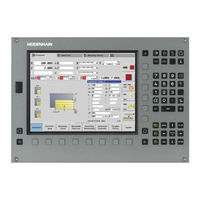
HEIDENHAIN MANUALPLUS 620 Manual (84 pages)
The Contouring Control for CNC and Cycle Lathes
Brand:
HEIDENHAIN
| Category:
Control Panel
| Size: 4.64 MB
Table of Contents
Contouring Control with Drive System from HEIDENHAIN
2
Table of Contents
3
Overview Tables
4
Specifications
6
HSCI Control Components
16
Accessories
28
Cable Overview
39
Technical Description
44
Data Transfer and Communication
61
Mounting Information
64
Overall Dimensions
66
General Information
79
Other HEIDENHAIN Controls
81
Subject Index
82
Advertisement
Related Products
HEIDENHAIN 620189-49
HEIDENHAIN 620189-46
HEIDENHAIN 620189-47
HEIDENHAIN 620189-44
HEIDENHAIN 620189-01
HEIDENHAIN 620189-51
HEIDENHAIN 620189-31
HEIDENHAIN 653217-57
HEIDENHAIN 653217-44
HEIDENHAIN 653217-23
HEIDENHAIN Categories
Media Converter
Measuring Instruments
Industrial Equipment
Control Systems
Controller
More HEIDENHAIN Manuals
Login
Sign In
OR
Sign in with Facebook
Sign in with Google
Upload manual
Upload from disk
Upload from URL