Omron 3G3MX2 User Manual
Mx2 series 200 v class three-phase input 0.1 to 15 kw 200 v class single-phase input 0.1 to 2.2 kw 400 v class three-phase input 0.4 to 15 kw
Hide thumbs
Also See for 3G3MX2:
- User manual (440 pages) ,
- Quick start manual (53 pages) ,
- Connection manual (34 pages)

Related Manuals for Omron 3G3MX2


Summary of Contents for Omron 3G3MX2
- Page 1 Cat. No. I570-E2-02A Born to drive machines Model: 3G3MX2 200 V Class Three-Phase Input 0.1 to 15 kW 200 V Class Single-Phase Input 0.1 to 2.2 kW 400 V Class Three-Phase Input 0.4 to 15 kW USER´S MANUAL...
- Page 3 OMRON. No patent liability is assumed with respect to the use of the information contained herein. Moreover, because OMRON is con- stantly striving to improve its high-quality products, the information contained in this manual is subject to change without notice.
- Page 4 WAY CONNECTED WITH THE PRODUCTS, WHETHER SUCH CLAIM IS BASED ON CONTRACT, WARRANTY, NEGLIGENCE, OR STRICT LIABILITY. In no event shall the responsibility of OMRON for any act exceed the individual price of the product on which liability is asserted.
- Page 5 PROGRAMMABLE PRODUCTS OMRON shall not be responsible for the user's programming of a programmable product, or any consequence thereof. Disclaimers CHANGE IN SPECIFICATIONS Product specifications and accessories may be changed at any time based on improvements and other reasons. It is our practice to change model numbers when published ratings or features are changed, or when significant construction changes are made.
-
Page 6: Table Of Contents
Table of contents Safety Messages ............. Hazardous High Voltage . -
Page 7: Table Of Contents
Omron EMC Recommendations ........ -
Page 8: Safety Messages
Safety Messages For the best results with the MX2 Series inverter, carefully read this manual and all of the warning labels attached to the inverter before installing and operating it, and follow the instructions exactly. Keep this manual handy for quick reference. - Page 9 !WARNING The user is responsible to ensure that all driven machinery, drive train mecha- nism not supplied by OMRON, and process line material are capable of safe operation at an applied frequency of 150% of the maximum selected fre- quency range to the AC motor. Failure to do so can result in destruction of equipment and injury to personnel should a single-point failure occur.
- Page 10 General Precautions - Read These First! !WARNING Rotating shafts and above-ground electrical potentials can be hazardous. Therefore, make sure that all electrical work conform to the National Electrical Codes and local regulations. Installation, alignment and maintenance must be performed only by qualified personnel. !Caution a) Class I motor must be connected to earth ground via low resistive path (<0.1)
-
Page 11: Index To Warnings And Cautions In This Manual
Index to Warnings and Cautions in This Manual Index to Warnings and Cautions in This Manual Cautions and Warnings for Orientation and Mounting Procedures !HIGH VOLTAGE Hazard of electrical shock. Disconnect incoming power before changing wir- ing, put on or take off optional devices or replace cooling fans. Wait ten (10) minutes before removing the front cover. - Page 12 “USE 60/75 C Cu wire only” or equivalent. For models 3G3MX2-AB004, -AB007, -AB022, -A2015, -A2022, -A2037, -A2055, -A2075...... 45 !WARNING “USE 75 C Cu wire only” or equivalent. For models 3G3MX2-AB002, -AB004, A2002, -A2004, -A2007, -A4022, -A4030, -A4040, -A4055, -A4075... 45 !WARNING “USE 60 C Cu wire only”...
- Page 13 Index to Warnings and Cautions in This Manual Wiring - Cautions for Electrical Practice !Caution Fasten the screws with the specified fastening torque in the table provided. Check for any loose screws. Otherwise, there is danger of fire....46 !Caution Be sure that the input voltage matches the inverter specifications;...
- Page 14 Index to Warnings and Cautions in This Manual !Caution Remarks for using ground fault interrupter breakers in the main power supply: Adjustable frequency inverter with integrated CE-filters and shielded (screened) motor cables have a higher leakage current toward earth GND. Especially at the moment of switching ON this can cause an inadvertent trip of ground fault interrupters.
- Page 15 Index to Warnings and Cautions in This Manual !WARNING Be sure not to operate electrical equipment with wet hands. Otherwise, there is the danger of electric shock..............… 192 !WARNING While the inverter is energized, be sure not to touch the inverter terminals even when the motor is stopped.
- Page 16 Index to Warnings and Cautions in This Manual !Caution The operation of the inverter can be easily changed from low speed to high speed. Be sure to check the capability and limitations of the motor and machine before operating the inverter. Otherwise, it may cause injury to per- sonnel.
-
Page 17: General Warnings And Cautions
General Warnings and Cautions !Caution Do not connect the megger to any control circuit terminals such as intelligent I/O, analog terminals, etc. Doing so could cause damage to the inverter. !Caution Never test the withstand voltage (HIPOT) on the inverter. The inverter has a surge protector between the main circuit terminals above and the chassis ground. - Page 18 General Warnings and Cautions !Caution Do not stop operation by switching OFF electromagnetic contactors on the primary or secondary side of the inverter. Ground fault interrupter Power Inverter Input L1, L2, L3 U, V, W Motor When there has been a sudden power failure while an operation instruction is active, then the unit may restart operation automatically after the power failure has ended.
- Page 19 General Warnings and Cautions !Caution EFFECTS OF POWER DISTRIBUTION SYSTEM ON INVERTER In the case below involving a general-purpose inverter, a large peak current can flow on the power supply side, sometimes destroying the converter mod- ule: 1. The unbalance factor of the power supply is 3% or higher. 2.
-
Page 20: Precautions For Safe Use
Precautions for Safe Use !Caution When using normally closed active state settings (C011 to C017) for exter- nally commanded Forward or Reverse terminals [FW] or [RV], the inverter may start automatically when the external system is powered OFF or discon- nected from the inverter! So do not use normally closed active state settings for Forward or Reverse terminals [FW] or [RV] unless your system design pro- tects against unintended motor operation. - Page 21 Underwriters Laborato- ries guidelines. !WARNING Use 60/75 C Cu wire only. (for models: 3G3MX2-A2001, -A2002, -A2004, -A2007, -AB015, -AB022, -A4004, -A4007, -A4015, -A4022, -A4030) !WARNING Use 75 C Cu wire only. (for models: 3G3MX2-AB001, -AB002, -AB004,...
- Page 22 ® Cautions, Warnings and Instructions !WARNING When protected by CC, G, J, or R class Fuses, or when Protected By A Circuit Breaker Having An Interrupting Rating Not Less Than 100,000 rms Symmetri- cal Amperes, 240 or 480 Volts Maximum. !WARNING Install device in pollution degree 2 environment.
- Page 23 ® Cautions, Warnings and Instructions Terminal symbols and Screw size Inverter Model Screw Size Required Wire range Torque (N-m) 3G3MX2-AB001, AWG16 (1.3mm 3G3MX2-AB002, 3G3MX2-AB004 3G3MX2-AB007 AWG12 (3.3mm 3G3MX2-AB015, AWG10 (5.3mm 3G3MX2-AB022 3G3MX2-A2001, AWG16 (1.3mm 3G3MX2-A2002, 3G3MX2-A2004, 3G3MX2-A2007 3G3MX2-A2015 AWG14 (2.1mm 3G3MX2-A2022 AWG12 (3.3mm...
- Page 24 Fuse Sizes The inverter shall be connected with a UL Listed Cartridge Nonrenewable fuse, rated 600Vac with the current ratings as shown in the table below. Inverter Model Type Rating 3G3MX2-AB001, Class J 10A, AIC 200kA 3G3MX2-AB002, 3G3MX2-AB004 3G3MX2-AB007 15A, AIC 200kA...
-
Page 25: Revision History
Revision History Revision History A manual revision history appears as a suffix to the catalogue number located at the lower left of the front and back covers. I570-E2-02 Cat. No. Revision code Revision code Revision date Description 2009 First version Second version January 2013 New functionality and IP54 models... - Page 26 Revision History xxiv...
-
Page 27: Getting Started
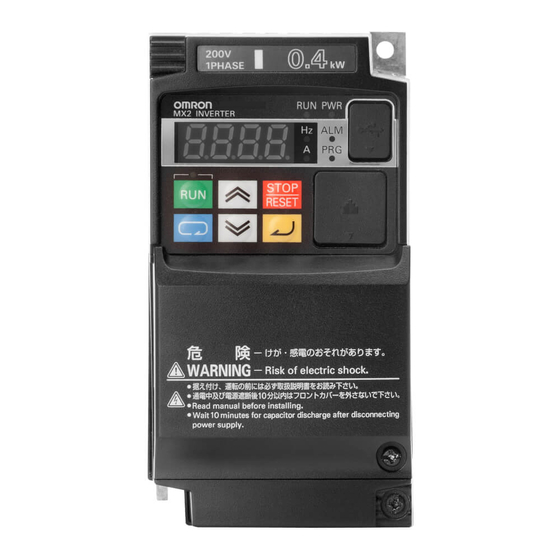
• Continuous operation at 100% torque within a 1:10 speed range (6/60 Hz/ 5/50 Hz) without motor derating. • Fan has ON/OFF selection to provide longer life for cooling fan. A full line of accessories from Omron is available to complete your motor application: • Integrated USB port for PC communication •... - Page 28 1-1-2 Inverter Specification Label The Omron MX2 inverters have product labels located on the right side of the housing, as pictured below. Be sure to verify that the specifications on the labels match your power source, and application safety requirements.
-
Page 29: Mx2 Inverter Specifications
Note that General Specifications on page 7 in this chap- ter apply to both voltage class groups. Footnotes for all specification tables fol- low the table below. Item Single-phase 200 V class Specifications 3G3MX2 inverters, 200 V models AB001 AB002 AB004F AB007 AB015... - Page 30 Note 11 Conforms to the test method specified in JIS C0040 (1999). For the model types excluded in the standard specifications, contact your Omron sales rep- resentative. Note 12 Watt losses are calculated values based on specification of main semi-con- ductors.
- Page 31 MX2 Inverter Specifications Section 1-2 Item Three-phase 200V class Specifications 3G3MX2 inverters, 200 V models A2001 A2002 A2004 A2007 A2015 A2022 Applica- 0.75 ble motor 0.75 size *2 Rated 200 V capacity (kVA) 240 V Loss at 100% load Efficiency at rated load % 89.5...
- Page 32 MX2 Inverter Specifications Section 1-2 Item Three-phase 400V class Specifications 3G3MX2 inverters, 400 V models A4004 A4007 A4015 A4022 A4030 A4040 Applica- 0.75 ble motor 0.75 size *2 Rated 380 V capacity (kVA) 480 V Loss at 100% load Efficiency at rated load % Rated input voltage Three-phase: 380 V-15% to 480 V+10%, 50/60 Hz±5%...
-
Page 33: General Specifications
MX2 Inverter Specifications Section 1-2 1-2-2 General Specifications The following table applies to all MX2 inverters. Item General Specifications Protective housing IP 20 Control method Sinusoidal Pulse Width Modulation (PWM) control Carrier frequency 2 kHz to 15 kHz (derating required depending on the model) Output frequency range 0.1 to 400 Hz Frequency accuracy... - Page 34 MX2 Inverter Specifications Section 1-2 Item General Specifications Output signal Intelligent output terminal RUN (run signal), FA1~FA5 (frequency arrival signal), OL,OL2 (overload advance notice signal), OD (PID deviation error signal), AL (alarm signal), 48 functions assignable OTQ (over/under torque threshold), UV (under-voltage), TRQ (torque limit signal), RNT (run time expired), ONT (power ON time expired), THM (ther- mal warning), BRK (brake release), BER (brake error), ZS (0Hz detection), DSE (speed deviation excessive), POK (positioning completion), ODc...
-
Page 35: Derating Curves
MX2 Inverter Specifications Section 1-2 1-2-3 Signal Ratings Detailed ratings are in . Signal / Contact Ratings Built-in power for inputs 24V DC, 100 mA maximum Discrete logic inputs 27 VDC maximum Discrete logic outputs 50 mA maximum ON state current, 27 VDC maximum OFF state voltage Analog output 10bit / 0 to 10 VDC, 1 mA... - Page 36 The following table shows which models need derating. 1-ph Derating 3-ph Derating 3-ph Derating 200V class 200V class 400V class 3G3MX2-AB001 – 3G3MX2-A2001 – 3G3MX2-A4004 – 3G3MX2-AB002 – 3G3MX2-A2002 O 3G3MX2-A4007 O 3G3MX2-AB004 O 3G3MX2-A2004 O 3G3MX2-A4015 – 3G3MX2-AB007 –...
- Page 37 MX2 Inverter Specifications Section 1-2 3G3MX2-AB004 CT (3.0 A) VT (3.5 A) output current 8 10 12 16 kH 8 10 12 14 kH Carrier frequency Carrier frequency 3G3MX2-A2004 CT (3.0 A) VT (3.5 A) 40°C individual 40°C side-by-side 40°C individual output current 40°C side-by-side...
- Page 38 MX2 Inverter Specifications Section 1-2 3G3MX2-A4040 CT (9.2 A) VT (11.1 A) 40°C individual 40°C individual 40°C side-by-side 40°C side-by-side output current 8 10 12 16 kH 8 10 12 14 kH Carrier frequency Carrier frequency 3G3MX2-A2075 CT (33.0 A) VT (40.0 A)
- Page 39 MX2 Inverter Specifications Section 1-2 3G3MX2-A4110 CT (24.0 A) VT (31.0 A) 50°C individual output current 40°C side-by-side 8 10 12 16 kH 8 10 12 14 kH Carrier frequency Carrier frequency 3G3MX2-A2150 CT (60.0 A) VT (69.0 A) output current 50°C individual...
-
Page 40: Introduction To Variable-Frequency Drives
1-3-1 The Purpose of Motor Speed Control for Industry Omron inverters provide speed control for 3-phase AC induction motors. You connect AC power to the inverter, and connect the inverter to the motor. Many applications benefit from a motor with variable speed, in several ways: •... - Page 41 1-3-4 Inverter Input and Three-phase Power The Omron MX2 Series of inverters includes two sub-groups: the 200 V class and the 400V class inverters. The drive described in this manual may be used in either the United States or Europe, although the exact voltage level for com- mercial power may be slightly different from country to country.
- Page 42 Introduction to Variable-Frequency Drives Section 1-3 The Omron inverter is a rugged and reliable device. The intention is for the inverter to assume the role of controlling power to the motor during all normal operations. Therefore, this manual instructs you not to switch off power to the inverter while the motor is running (unless it is an emergency stop).
- Page 43 Introduction to Variable-Frequency Drives Section 1-3 1-3-8 Velocity Profiles The MX2 inverter is capable of Speed Set speed sophisticated speed control. graphical representation that Accel Decel capability will help you understand and configure the associated param- eters. This manual makes use of the Velocity Profile velocity profile graph used in indus- try (shown at right).
-
Page 44: Frequently Asked Questions
Frequently Asked Questions Section 1-4 Frequently Asked Questions Q. What is the main advantage in using an inverter to drive a motor, com- pared to alternative solutions? A. An inverter can vary the motor speed with very little loss of efficiency, unlike mechanical or hydraulic speed control solutions. - Page 45 Q. How many poles should the motor have? A. Omron inverters can be configured to operate motors with 2, 4, 6, or 8 poles. The greater the number of the poles, the slower the top motor speed will be, but it will have higher torque at the base speed.
-
Page 46: International Standards
Low-voltage directive EN 61800-5-1 EMC directive EN 61800-3 UL508C CSA-C22.2 No. 14 Safety functions are supported. The 3G3MX2 series inverters meet requirements for IEC 60204-1 Stop Cate- gory 0 operation and ISO 13849-1 Performance Level PLd of the Machinery Directive. -
Page 47: Inverter Mounting And Installation
SECTION 2 Inverter Mounting and Installation Orientation to Inverter Features 2-1-1 Unpacking and Inspection Please take a few moments to unpack your new MX2 inverter and perform these steps: 1. Look for any damage that may have occurred during transportation. 2. - Page 48 Orientation to Inverter Features Section 2-1 Power Wiring Access - First, ensure no power source is connected to the inverter. If power has been connected, verify that the Power LED is OFF and then wait ten minutes after power down to proceed. After removing the termi- nal cover and front housing cover, the housing partitions that cover the power and motor wiring exits will be able to slide upward as shown below.
- Page 49 Orientation to Inverter Features Section 2-1 2-1-3 User removable parts by each inverter size. IP20 1-phase 200 V 0.1, 0.2, 0.4 kW 3-phase 200 V 0.1, 0.2, 0.4, 0.75 kW Even if the W × H dimension is the same, the D dimension for the cooling fin varies depending on the capacity.
- Page 50 Orientation to Inverter Features Section 2-1 3-phase 200 V 3.7 kW 3-phase 400V 4.0 kW 3-phase 200 V 5.5, 7.5 kW 3-phase 400 V 5.5, 7.5 kW (1) Cooling fan cover (5) Terminal block cover (2) Cooling fan (6) Optional board cover (3) Cooling fin (7) Backing plate (4) Main housing...
- Page 51 Orientation to Inverter Features Section 2-1 3-phase 200 V 11 kW 3-phase 400 V 11, 15 kW 3-phase 200 V 15 kW (1) Cooling fan cover (5) Terminal block cover (2) Cooling fan (6) Optional board cover (3) Cooling fin (7) Backing plate (4) Main housing...
- Page 52 Orientation to Inverter Features Section 2-1 IP54 Mounting plate Air outlet Front cover Window for MX2 inverter display Lock for front cover USB connector (mini-B) Panel hole for accessory...
- Page 53 Orientation to Inverter Features Section 2-1...
-
Page 54: Basic System Description
Basic System Description Section 2-2 Basic System Description A motor control system will obviously include a motor and inverter, as well as a circuit breaker or fuses for safety. If you are connecting a motor to the inverter on a test bench just to get started, that's all you may need for now. But a system can also have a variety of additional components. -
Page 55: Step-By-Step Basic Installation
Step-by-Step Basic Installation Section 2-3 !WARNING In the cases below involving a general-purpose inverter, a large peak current can flow on the power supply side, sometimes destroying the converter mod- ule: 1. The unbalance factor of the power supply is 3% or higher. 2. - Page 56 Step-by-Step Basic Installation Section 2-3 !Caution Be sure not to let the foreign matter enter vent openings in the inverter hous- ing, such as wire clippings, spatter from welding, metal shavings, dust, etc. Otherwise, there is the danger of fire. !Caution Be sure to install the inverter in a place that can bear the weight according to the specifications in the text (Chapter 1, Specifications Tables).
- Page 57 Step-by-Step Basic Installation Section 2-3 Mounting Orientation and Spacing Always install the housing in an upright position. Leave 10 cm space above and below the housing for proper cooling. Leave 10 cm space to the left and to the right for replacement of the dust filter. Removing the Front Cover !WARNING Turn off the power supply before removing the cover.
- Page 58 Step-by-Step Basic Installation Section 2-3 Ventilation fan Ventilation fan Inverter Inverter (Good example) (Bad example) Keep the Inverter away from heating elements (such as a Braking Resistor, reactor, etc.). Although side-by-side installation is possible. The ambient temperature of the installation site must not exceed 40C and the carrier frequency and output current must be derated if side-by-side installation is used.
-
Page 59: Installation Method
Step-by-Step Basic Installation Section 2-3 2-3-3 Installation/Removal Method of the Terminal Block Cover 2-3-3-1 Removal method Loosen the screw(s) (1 or 2 While pressing the bottom of the locations) securing the terminal block cover in the direction terminal block cover. of the arrow, pull the terminal block cover downward to remove. - Page 60 Locate the applicable drawing on the following pages for your inverter. Dimen- sions are given in millimeters (inches) format. Ø4.5 8.8.8.8. Power Type W (mm) H (mm) D (mm) D1 (mm) Single-phase 3G3MX2-AB001 13.5 200V 3G3MX2-AB002 3G3MX2-AB004 122.5 3-phase 200 V 3G3MX2-A2001 13.5 3G3MX2-A2002 3G3MX2-A2004 122.5...
- Page 61 Step-by-Step Basic Installation Section 2-3 2-Ø4.5 8.8.8.8. Power Type W (mm) H (mm) D (mm) D1 (mm) Single-phase 3G3MX2-AB007 170.5 200 V 3G3MX2-AB015 3G3MX2-AB022 3-phase 200 V 3G3MX2-A2015 170.5 3G3MX2-A2022 3-phase 400V 3G3MX2-A4004 143.5 3G3MX2-A4007 170.5 3G3MX2-A4015 3G3MX2-A4022 3G3MX2-A4030...
- Page 62 Step-by-Step Basic Installation Section 2-3 2-Ø4.5 8.8.8.8. Power Type W (mm) H (mm) D (mm) D1 (mm) 3-phase 200 V 3G3MX2-A2037 170,5 3-phase 400 V 3G3MX2-A4040...
- Page 63 Step-by-Step Basic Installation Section 2-3 Ø 8.8.8.8. Power Type W (mm) H (mm) D (mm) D1 (mm) 3-phase 200 V 3G3MX2-A2055 73.3 3G3MX2-A2075 3-phase 400 V 3G3MX2-A4055 3G3MX2-A4075...
- Page 64 Step-by-Step Basic Installation Section 2-3 2- Ø 7 8.8.8.8. Power Type W (mm) H (mm) D (mm) D1 (mm) 3-phase 200 V 3G3MX2-A2110 3-phase 400 V 3G3MX2-A4110 3G3MX2-A4150...
- Page 65 Step-by-Step Basic Installation Section 2-3 2-Ø7 8.8.8.8. Power Type W (mm) H (mm) D (mm) D1 (mm) 3-phase 200 V 3G3MX2-A2150...
- Page 66 Step-by-Step Basic Installation Section 2-3 IP54 179.5 Figure 1 169.5 292.7 292.7 Figure 1 Power Type Single-phase 200 V 3G3MX2-DB001-E 3G3MX2-DB002-E 3G3MX2-DB004-E 3-phase 200 V 3G3MX2-D2001-E 3G3MX2-D2002-E 3G3MX2-D2004-E 3G3MX2-D2007-E 309.5 Figure 2 299.5 279.5 298.9 317.7 Figure 2 Power Type...
- Page 67 Step-by-Step Basic Installation Section 2-3 Figure 2 Power Type 3-phase 400 V 3G3MX2-D4004-EC 3G3MX2-D4007-EC 3G3MX2-D4015-EC 3G3MX2-D4022-EC 3G3MX2-D4030-EC 3G3MX2-D4040-EC Figure 3 299.5 Figure 3 Power Type 3-phase 200 V 3G3MX2-D2055-EC 3G3MX2-D2075-EC 3-phase 400 V 3G3MX2-D4055-EC 3G3MX2-D4075-EC Figure 4 18.7 329.7 Figure 4...
- Page 68 “USE 60/75 C Cu wire only” or equivalent. For models 3G3MX2-A2001, -A2002, -A2004, -A2007, -AB015, -AB022, -A4004, -A4007, -A4015, -A4022, -A4030 !WARNING “USE 75 C Cu wire only” or equivalent. For models 3G3MX2-AB001, -AB002, -AB004, -AB007, -A2015, -A2022, -A2037, A2055, A2075, -A2110, -A2150, -A4040, -A4055, -A4075, -A4110 and -A4150 !WARNING “Suitable for use on a circuit capable of delivering not more than 100k rms...
- Page 69 Step-by-Step Basic Installation Section 2-3 IP54 Connect all wiring via wiring access holes (in the botttom of the MX2 IP54 mounting plate). Connect the AC power supply voltage to the EMC filter. Connect the three phase motor to the motor output terminals of the MX2 inverter.
- Page 70 Step-by-Step Basic Installation Section 2-3 Note: Use IP54 or better cable glands to prevent moisture from entering the unit. Not doing so might result in damaging the unit. Note: Use cable glands of right size to prevent moisture from entering the unit.
- Page 71 Inverter Model Wiring Applicable equipment Power Lines Signal Lines Fuse (UL-rated, class J, 600 V) ¼ 3G3MX2-AB001 AWG16 / 1.3 mm² (75°C only) 18 to 28 AWG / 10 A 0.14 to ½ ¼ 3G3MX2-AB002 0.75 mm² 0.55 0.4 ¾...
- Page 72 Otherwise, there is the danger of fire. Types Screw Width (mm) Tightening Diameter Torque (N·m) 3G3MX2 - AB001, AB002, AB004 M3.5 3G3MX2 - A2001, A2002, A2004, A2007 3G3MX2 - AB007, AB015, AB022 3G3MX2 - A2015, A2022, A2037 3G3MX2 - A4004, A4007, A4015,...
- Page 73 Step-by-Step Basic Installation Section 2-3 2-3-9 Inverter output terminal (U/T1, V/T2, W/T3) For connection of the output terminal, use the compatible cable or a cable with a larger section. Otherwise, the output voltage between the Inverter and the motor may drop. Do not mount a phase advance capacitor or surge absorber, because these devices may cause the Inverter to trip or cause damage to the capacitor or surge absorber.
- Page 74 Step-by-Step Basic Installation Section 2-3 Single-phase 200 V 0.75 to 2.2 kW Three-phase 200 V 1.5, 2.2 kW Three-phase 400 V 0.4 to 3.0 kW Single-phase Three-phase RB PD/+1 P/+ N/- RB PD/+1 P/+ N/- N U/T1 V/T2 W/T3 R/L1 S/L2 T/L3 U/T1 V/T2 W/T3 Power input Output to Motor...
- Page 75 • Single-phase 200 to 240 V 50/60 Hz(0.1 kW~2.2 kW) for 3G3MX2-AB models • Three-phase 200 to 240 V 50/60 Hz (0.1 kW~15 kW) for 3G3MX2-A2 models • Three-phase 380 to 480 V 50/60 Hz (0.4 kW~15 kW) for 3G3MX2-A4 models !Caution Be sure not to power a three-phase-only inverter with single phase power.
- Page 76 Step-by-Step Basic Installation Section 2-3 !Caution Be sure not to connect an AC power supply to the output terminals. Other- wise, there is the possibility of damage to the inverter and the danger of injury and/or fire. MX2 Inverter Output to Motor Power Input !Caution Remarks for using ground fault interrupter breakers in the main power supply: Adjustable frequency inverter with integrated CE-filters and shielded...
- Page 77 Step-by-Step Basic Installation Section 2-3 2-3-12 Wire the Inverter Output to Motor Step 4 The process of motor selection is beyond the scope of this manual. However, it must be an AC induction motor with three phases. It should also come with a chassis ground lug.
- Page 78 Step-by-Step Basic Installation Section 2-3 MX2 control wiring quick reference (IP20) Breaker, MCCB or GFI (T1) Power source, (L1 ) Motor 3-phase or (T2) 1-phase, per inverter model (L2 ) (T3) N (L3 ) PD/+1 DC reactor Intelligent inputs, (optional) 7 terminals Forward NOTE:...
- Page 79 Step-by-Step Basic Installation Section 2-3 MX2 control wiring quick reference (IP54) Breaker, MCCB or GFI (T1) Power source, (L1 ) Motor 3-phase or (T2) 1-phase, per Filter (L2 ) inverter model (T3) N(L3 ) PD/+1 DC reactor (optional) Intelligent inputs, 7 terminals Forward NOTE:...
- Page 80 Step-by-Step Basic Installation Section 2-3 2-3-15 Name of Parts Inside the Terminal Block Cover Modbus-RTU Termination resistor selector switch Safety function selector switch Disable Enable (Factory default) (Factory default) USB connector (mini-B) Connector for optional board Connector for Digital Operator (RJ45) EDM function selector switch P1 terminal Multi-function contact terminal block...
- Page 81 Step-by-Step Basic Installation Section 2-3 2-3-16 Uncover the Inverter Vents Step 5 After mounting and wiring the inverter, Ventilation holes (top) remove any covers from the inverter hous- ing. This includes material over the side ven- tilation ports. !WARNING Make sure the input power to the inverter is OFF.
-
Page 82: Powerup Test
3. Get an introduction to the use of the built-in operator keypad. The powerup test gives you an important starting to ensure a safe and suc- cessful application of the Omron inverter. We highly recommend performing this test before proceeding to the other chapters in this manual. - Page 83 Powerup Test Section 2-4 !Caution Check the following before and during the Powerup test. Otherwise, there is the danger of equipment damage. • Is the shorting bar between the [+1] and [+] terminals installed? DO NOT power or operate the inverter if the jumper is removed. •...
-
Page 84: Using The Front Panel Keypad
Using the Front Panel Keypad Section 2-5 Using the Front Panel Keypad Please take a moment to familiarize yourself with the keypad layout shown in the figure below. The display is used in programming the inverter's parame- ters, as well as monitoring specific parameter values during operation. (4) RUN LED (1) POWER LED (5) Monitor LED [Hz]... - Page 85 Using the Front Panel Keypad Section 2-5 2-5-1 Keys, Modes, and Parameters The purpose of the keypad is to provide a way to change modes and parameters. The term function applies to both monitoring modes and parameters. These are all acces- sible through function codes that are primary 4-character codes.
- Page 86 Using the Front Panel Keypad Section 2-5 2-5-2 Keypad Navigation Map The MX2 Series inverter drives have many programmable functions and parameters. Chapter 3 will cover these in detail, but you need to access just a few items to perform the powerup test. The menu structure makes use of function codes and parameter codes to allow programming and monitoring with only a 4-digit display and keys and LEDs.
- Page 87 Using the Front Panel Keypad Section 2-5 [Setting example] After power ON, changing from display to change the (carrier frequency) data. Data of d001 will be shown on the Press key to show display after the first power ON the function code 0.00 d001...
- Page 88 Using the Front Panel Keypad Section 2-5 2-5-3 Selecting Functions and Editing Parameters To prepare to run the motor in the powerup test, this section will show how to configure the necessary parameters: 1. Select the digital operator as the source of motor speed command ().
- Page 89 Using the Front Panel Keypad Section 2-5 If the Potentiometer Enable LED is OFF, follow these steps below (the table resumes action from the end of the previous table). Action Display Func./Parameter (Starting point) Speed command source setting A001 Run command source setting Press the A002 ...
- Page 90 Using the Front Panel Keypad Section 2-5 To set the motor voltage, follow the steps on the following table. Action Display Func./Parameter (Starting point) Base frequency setting A003 AVR voltage select Press the key and hold until –> A082 Default value for AVR voltage: Press the A230 200 V class= 230 VAC...
- Page 91 Using the Front Panel Keypad Section 2-5 5. Set the Number of Motor Poles – The motor's internal winding arrange- ment determines its number of magnetic poles. The specification label on the motor usually indicates the number of poles. For proper operation, verify the parameter setting matches the motor poles.
- Page 92 Using the Front Panel Keypad Section 2-5 2-5-4 Monitoring Parameters with the Display After using the keypad for parameter editing, it's a good idea to switch the inverter from Program Mode to Monitor Mode. The PRG LED will be OFF, and the Hertz or Ampere LED indicates the display units.
- Page 93 Using the Front Panel Keypad Section 2-5 2-5-6 Single-Digit Edit Mode If a target function code or data is far from current data, using the single-digit edit mode makes it quicker. Pressing the up key and down key at the same time leads you to go into the digit-to-digit changing mode.
- Page 94 Note Some factory automation devices such as PLCs have alternative Run/Pro- gram modes; the device is in either one mode or the other. In the Omron inverter, however, Run Mode alternates with Stop Mode, and Program Mode alternates with Monitor Mode.
-
Page 95: Configuring Drive Parameters
Choosing a Programming Device 3-1-1 Introduction Omron variable frequency drives (inverters) use the latest electronics technol- ogy for getting the right AC waveform to the motor at the right time. The bene- fits are many, including energy savings and higher machine output or productivity. -
Page 96: Using The Keypad Devices
Using the Keypad Devices Section 3-2 Using the Keypad Devices The MX2 Series inverter front keypad contains all the elements for both moni- toring and programming parameters. The keypad layout is pictured below. All other programming devices for the inverter have a similar key arrangement and function. - Page 97 Using the Keypad Devices Section 3-2 3-2-2 Operational Modes The RUN and PRG LEDs tell just part of the story; Run Mode and Program Stop Modes are independent modes, not opposite modes. In the state diagram to the right, Run alternates with Stop, and Program Mode alternates with Monitor Mode.
- Page 98 Using the Keypad Devices Section 3-2 3-2-5 Dual Rate Selection The MX2 series inverter has Dual Rate, so that it can work in two different types of load condition, Constant torque application and Variable torque appli- cation. Select parameter depending on your application.
- Page 99 Using the Keypad Devices Section 3-2 Func. code Name Func. code Name C054 Over-torque/under-torque selection P033 Torque reference input selection C055 Overtorque level (FW, PW) P034 Torque reference setting C056 Overtorque level (RV, RG) P036 Torque bias mode C057 Overtorque level (RV, PW) P037 Torque bias value C058...
-
Page 100: D" Group: Monitoring Functions
“D” Group: Monitoring Functions Section 3-3 “D” Group: Monitoring Functions You can access important parameter values with the “D” Group monitoring functions, whether the inverter is in Run Mode or Stop Mode. After selecting the function code number for the parameter you want to monitor, press the ... - Page 101 “D” Group: Monitoring Functions Section 3-3 “D” Function Units Mode Func. Name Description Edit Code Power ON time monitor Displays total time the inverter has been pow- – hours ered up in hours. Range is 0 to 9999 / 1000 to 9999 / 100 to 999 (10,000 to 99,900) ...
- Page 102 “D” Group: Monitoring Functions Section 3-3 “D” Function Units Mode Func. Name Description Edit Code Regenerative braking load rate Usage ratio of integrated brake chopper, – monitor range is 0.0~100.0 Electronic thermal monitor Accumulated value of electronic thermal –...
- Page 103 “D” Group: Monitoring Functions Section 3-3 3-3-2 Output Frequency Monitor [d001] Displays the output frequency of the inverter. During stop, “0.00” is displayed. The monitor LED indicator “Hz” is lit while the d001 setting is displayed. Parameter Default Function name Data Unit setting...
- Page 104 “D” Group: Monitoring Functions Section 3-3 3-3-5 PID Feedback Value Monitor [d004] When “01: Enabled” or “02: Reverse output enabled” is selected in PID Selection (A071), the PID feedback value can be monitored. Also, conversion is possible using PID Scale (A075). “d004 display”...
- Page 105 “D” Group: Monitoring Functions Section 3-3 3-3-7 Multi-function Output Monitor [d006] The LED lighting position indicates the output status of the multi-function output terminals. The output status of the built-in CPU is indicated. This is not the status of the control circuit terminal.
- Page 106 “D” Group: Monitoring Functions Section 3-3 3-3-9 Real Frequency Monitor [d008] The actual-frequency monitor d008 will reflect the real motor speed always that the encoder feedback is active by parameter P003=01, independently of parameter A044 and P012 settings. Parameter Default Function name Data Unit...
- Page 107 “D” Group: Monitoring Functions Section 3-3 3-3-13 Output Voltage Monitor [d013] Displays the output voltage of the inverter. Parameter Default Function name Data Unit setting d013 Output voltage monitor 0.0 to 600.0 • Set Motor Incoming Voltage Selection (A082/A282) correctly. The correct value may not be displayed.
- Page 108 “D” Group: Monitoring Functions Section 3-3 3-3-16 Total RUN Time [d016] Displays the total RUN time of the inverter. This parameter is saved in the EEPROM when the power is shut off. Parameter Default Function name Data Unit setting d016 Total RUN time 0.0 to 9,999.
- Page 109 “D” Group: Monitoring Functions Section 3-3 • The capacitor service life is calculated every 10 minutes. If the inverter is turned on/off frequently within this interval, the capacitor service life cannot be correctly diagnosed. • The cooling fan life assessment function is not available for 1-phase 200V class motors of 0.4 kW max.
- Page 110 “D” Group: Monitoring Functions Section 3-3 3-3-23 Inverter Mode [d060] Displays the current inverter mode. The inverter mode is changed using b171. Parameter Default Function name Data Unit setting d060 Inverter mode IM (induction motor) heavy load mode IM (induction motor) light load mode Permanent magnet motor control...
- Page 111 “D” Group: Monitoring Functions Section 3-3 3-3-26 Fault Frequency Monitor [d080] Displays the number of times the inverter has tripped. This number is saved in the EEPROM when the power is turned off. Parameter Default Function name Data Unit setting d080 Fault frequency monitor 0.
- Page 112 “D” Group: Monitoring Functions Section 3-3 3-3-30 Regenerative Braking Load Rate Monitor [d103] Displays a regenerative braking load rate. When the displayed value exceeds the value set in the Usage Rate of Regenerative Braking (b090), the inverter trips beacuse of “E06 (Braking resistor overload protection)”. Parameter Default Function name...
- Page 113 “D” Group: Monitoring Functions Section 3-3 3-3-34 PID Deviation Monitor [d153] It displays the PID deviation into d153 monitor. It only operates when PID function is effective (A071=01 or 02). Parameter Default Function name Data Unit setting d153 PID deviation monitor -9999.00 to 9999.00 A071 PID selection...
- Page 114 “D” Group: Monitoring Functions Section 3-3 3-3-36 Local Monitoring with Keypad Connected The MX2 inverter's serial port may be connected to an external digital opera- tor. During those times, the inverter keypad keys will not function (except for the Stop key). However, the inverter's 4-digit display still provides the Monitor ...
-
Page 115: F" Group: Main Profile Parameters
“F” Group: Main Profile Parameters Section 3-4 “F” Group: Main Profile Parameters The basic frequency (speed) Output profile is defined by parameters frequency F002 F003 contained in the “F” Group as shown to the right. The set run- A004 ning frequency is in Hz, but F001 acceleration and deceleration are specified in the time dura-... -
Page 116: A" Group: Standard Functions
“A” Group: Standard Functions Section 3-5 “A” Group: Standard Functions The inverter provides flexibility in how you control Run/Stop operation and set the output frequency (motor speed). It has other control sources that can override the settings. Parameter sets the source selection for ... - Page 117 “A” Group: Standard Functions Section 3-5 Run Command Source Setting - For parameter , the following table pro- vides a further description of each option, and a reference to other page(s) for more information. Code Run Command Source Refer to page(s)… ...
- Page 118 “A” Group: Standard Functions Section 3-5 Multi-speed inputs CF1-4,SF1-7 Multi-step speed Frequency A021 - A035 setting [O]+[OI] [AT] terminal is [AT] [AT] selection active A005 terminal Analog voltage input [O] Analog current input [OI] Remote operator POT [VR] Operator control Digital operator A020/A220=F001 Frequency...
- Page 119 “A” Group: Standard Functions Section 3-5 3-5-1 Basic Parameter Settings These settings affect the most fundamental behavior of the inverter - the out- puts to the motor. The frequency of the inverter's AC output determines the motor speed. You may select from three different sources for the reference speed.
- Page 120 “A” Group: Standard Functions Section 3-5 Adjusting [O-L] characteristics - In Max frequency the graph to the right, select the active portion of the input A012 voltage range. Parameters select the start and end frequency A015=00 of the converted output frequency range, respectively.
- Page 121 “A” Group: Standard Functions Section 3-5 “A” Function Defaults Mode Func. Name Description Units Edit Code O start selection Two options; select codes: – ... Start FQ ... 0 Hz O, O2, OI sampling Range n = 1 to 31, Spl.
- Page 122 “A” Group: Standard Functions Section 3-5 occurs, the filter naturally has a delayed response. Due to the deadband fea- ture ( ), the final output changes only when the 30-sample average moves past the deadband threshold. !Tip The deadband feature is useful in applications that requires a very stable out- put frequency but use an analog input for the speed reference.
- Page 123 “A” Group: Standard Functions Section 3-5 There are two ways for speed selection, that are “binary operation” and “bit operation”. For binary operation ( ), you can select 16 speeds by combination of 4 digital inputs. And for bit operation ( ), you can select 8 speeds by using 7 digital inputs.
- Page 124 “A” Group: Standard Functions Section 3-5 The example with eight speeds Speed in the figure below shows how input switches configured for SF1-SF7 functions can change the motor speed in real time. [SF1] NOTE: Speed 0 depends on [SF2] parameter value.
- Page 125 “A” Group: Standard Functions Section 3-5 c) Set the desired output frequency by pressing the keys. d) Press the key once to store the set frequency. When this occurs, indicates the output frequency of Multi-speed n. e) Press the key once to confirm that the indication is the same as the set frequency.
- Page 126 “A” Group: Standard Functions Section 3-5 instantaneous, but you can choose from six modes for the best method for stopping the jog operation. “A” Function Defaults Mode Func. Name Description Units Edit Code Jogging frequency Defines limited speed for jog, 6.00 range is from start frequency to 9.99 Hz...
- Page 127 “A” Group: Standard Functions Section 3-5 Option Terminal Function State Description Code Symbol Name ~ Valid for inputs: Example (requires input configura- tion – see page 153): =, >, Required settings: >, Notes: • No jogging operation is performed when the set value of jogging frequency ...
- Page 128 “A” Group: Standard Functions Section 3-5 quency setting ( ) automatically. (The inverter regard the value of free-setting V/F frequency 7 ( ) as the maximum frequency.) Output voltage (V) V7 ( b113) V6 ( b111) V5 ( b109) V4 ( b107) V1 ( b101) V2,3 ( b103,b105)
- Page 129 “A” Group: Standard Functions Section 3-5 Voltage gain - Using parameter A045=100 A045 you can modify the voltage gain of the inverter (see graph at 100% right). This is specified as a percent- age of the full scale output voltage. The gain can be set from 20% to 100%.
- Page 130 “A” Group: Standard Functions Section 3-5 “A” Function Defaults Mode Func. Name Description Units Edit Code V/f characteristics selection Four available V/f curves; – ... VC (Constant torque) 2nd V/f characteristics selec- – tion ... VP (Reduced torque) ...
- Page 131 “A” Group: Standard Functions Section 3-5 3-5-5 DC Braking (DB) Settings Normal DC braking performance Running Free run DC brake – The DC braking feature can pro- vide additional stopping torque when compared to a normal decel- eration to a stop. DC braking is particularly useful at low speeds A053 A055...
- Page 132 “A” Group: Standard Functions Section 3-5 DC braking performance at start can also be set separately ( And carrier frequency of DC braking performance can also be set separately “A” Function Defaults Mode Func. Name Description Units Edit Code ...
- Page 133 “A” Group: Standard Functions Section 3-5 3. Scenario 3 – The Run command is applied from the operator keypad. When the [DB] terminal is ON, DC braking is applied after the delay time set by expires. The motor is in a free-running (coasting) condition. When the [DB] terminal is OFF again, the inverter output remains OFF.
- Page 134 “A” Group: Standard Functions Section 3-5 Jump Frequencies - Some motors or machines exhibit resonances at partic- ular speed(s), which can be destructive for prolonged running at those speeds. The inverter has up to three jump frequencies as shown in the graph. The hysteresis around the jump frequencies causes the inverter output to skip around the sensitive frequency values.
-
Page 135: Pid Control
“A” Group: Standard Functions Section 3-5 “A” Function Defaults Mode Func. Name Description Units Edit Code Acceleration stop frequency Sets the frequency to hold accel- 0.00 eration, range is 0.00 to 400.00 Acceleration stop time Sets the duration of acceleration sec. - Page 136 “A” Group: Standard Functions Section 3-5 “A” Function Defaults Mode Func. Name Description Units Edit Code PID sleep function action Sets the threshold for the action, 0.00 threshold set range 0.00~400.00 Hz PID sleep function action delay Sets the delay time for the action, time set range 0.0~25.5 sec...
- Page 137 “A” Group: Standard Functions Section 3-5 Setpoint Scale factor (Target) Standard setting Frequency A075 F001 Scale factor F001 source select Reciprocal Multi-speed P gain A001 setting A072 A075 A020 A035 Frequency I gain setting POT meter on A073 ext. panel D gain Process variable (Feedback) A074...
- Page 138 “A” Group: Standard Functions Section 3-5 The diagram below shows PID setpoint changes and the related output fre- quency behavior when a limit value in exists. Limit imposed on output Output limit A078 PID Setpoint Output freq. A078 Limit imposed Output limit on output Deviation (error) Inversion - In typical heating loops or ventilation loops, an...
- Page 139 “A” Group: Standard Functions Section 3-5 3-5-9 PID Sleep Function The inverter shuts off the output when the PID output becomes less than the specified value ( ) in case of PID is set enabled, or shuts off when the fre- quency command becomes less than the specified value in case of PID is set disabled.
- Page 140 “A” Group: Standard Functions Section 3-5 3-5-11 Energy Savings Mode / Optional Accel/Decel Energy Saving Mode - This function allows the inverter to deliver the mini- mum power necessary to maintain speed at any given frequency. This works best when driving variable torque characteristic loads such as fans and ...
- Page 141 “A” Group: Standard Functions Section 3-5 3-5-12 Second Acceleration and Deceleration Functions The MX2 inverter features two-stage acceleration and deceleration ramps. This gives flexibility in the profile shape. You can specify the frequency transi- tion point, the point at which the standard acceleration ( ) or deceleration ...
- Page 142 “A” Group: Standard Functions Section 3-5 Switch between accelerations and decelerations could be done also Target frequency using terminal [2CH], when this input second is turned ON the inverter changes the Output rate of acceleration and deceleration initial frequency from the initial settings ( ...
- Page 143 “A” Group: Standard Functions Section 3-5 “A” Function Defaults Mode Func. Name Description Units Edit Code Acceleration curve parameter Range is 01 to 10 – Deceleration curve parameter Range is 01 to 10 – EL-S-curve ratio 1 during Range is 0 to 50% acceleration...
- Page 144 “A” Group: Standard Functions Section 3-5 ~ Curvature of EL-S-curve When using EL-S-curve pattern, you can set the curvatures individually for acceleration and deceleration. If all the curvatures are set to 50%, the EL-S- curve pattern will be equivalent to the S-curve pattern. Curvature for A151 A152...
- Page 145 “A” Group: Standard Functions Section 3-5 Analog Input Calculate Function - The inverter can mathematically combine two input sources into one value. The Calculate function can either add, sub- tract, or multiply the two selected sources. This provides the flexibility needed by various applications.
- Page 146 “A” Group: Standard Functions Section 3-5 Frequency source setting A001 Remote operator POT Control terminal Output frequency setting Function setting F001 ModBus network input Calculate function output Option board A146 ADD frequency A145 ADD direction select [ADD] Intelligent input “A” Function Defaults Mode Func.
-
Page 147: B" Group: Fine Tuning Functions
“B” Group: Fine Tuning Functions Section 3-6 “B” Group: Fine Tuning Functions The “B” Group of functions and parameters adjust some of the more subtle but useful aspects of motor control and system configuration. 3-6-1 Automatic Restart Mode The restart mode determines how the inverter will resume operation after a fault causes a trip event. - Page 148 “B” Group: Fine Tuning Functions Section 3-6 Automatic restart (retry) related parameters. “B” Function Defaults Mode Func. Name Description Units Edit Code Retry selection Select inverter restart method, – Five option codes: ... Trip (Alarm) ... 0 Hz start ...
- Page 149 “B” Group: Fine Tuning Functions Section 3-6 3-6-2 Active Frequency Matching Restart Goal of the active frequency matching is the same as normal frequency matching. Difference is the method. Please select the suitable one for your application. “B” Function Defaults Mode Func.
- Page 150 “B” Group: Fine Tuning Functions Section 3-6 “B” Function Defaults Mode Func. Name Description Units Edit Code Free setting, electronic thermal Range is 0.00 to rated current 0.00 Amps current 2 Free setting, electronic thermal Range is 0.00 to 400.00 Hz 0.00 frequency 3 ...
- Page 151 “B” Group: Fine Tuning Functions Section 3-6 • Reduced Torque (=) 3G3MX2-A2015**, Base FQ=60Hz, ND setting (Rated current 9.6A= b012) Example: Reduction rate 60Hz (Reduction rate: x1.0) 20Hz (Reduction rate: x0.8) Trip time Trip time x1.0 x0.8 x0.6 11.1 11.5 14.4[A]...
- Page 152 “B” Group: Fine Tuning Functions Section 3-6 Thermal decrement mode Off (b910 = 00) With this method the thermal level increases when the output current is bigger than internal level value (defined in b012). The increase rate is proportional to the overload value.
- Page 153 “B” Group: Fine Tuning Functions Section 3-6 Thermal decrement mode by time constant (b910 = 03) For this option the decrement is performed by a time constant value defined on parameter b912. The curve from 100% to 0 is approximately 5 times the b912 value. Output current Thermal level Overload counter d104...
- Page 154 “B” Group: Fine Tuning Functions Section 3-6 3-6-4 Current limitation Related Functions Overload Restriction: If Motor inverter's output current Restriction area current exceeds a preset current level you specify during acceleration or constant speed, the overload restriction feature automatically reduces the output frequency during powering drive (and can Regenerating...
- Page 155 “B” Group: Fine Tuning Functions Section 3-6 • The Over-current Trip Suppression feature does not operate by maintain- ing a constant motor current. So it is still possible to have an over-current trip event during extreme acceleration. “B” Function Defaults Mode Func.
- Page 156 “B” Group: Fine Tuning Functions Section 3-6 Option Terminal Function State Description Code Symbol Name Parameter sets , , Overload restriction are enabled. source Parameter sets , , changeover are enabled. ~ Valid for inputs: ~ Required settings: 3-6-5 Software Lock Mode The software lock function keeps personnel from accidentally changing...
- Page 157 “B” Group: Fine Tuning Functions Section 3-6 “B” Function Defaults Mode Func. Name Description Units Edit Code Soft lock selection Prevents parameter changes, in – five options, option codes: Lock (SFT) (Data other than b031 cannot be changed when terminal SFT is ON.) ...
- Page 158 “B” Group: Fine Tuning Functions Section 3-6 For 11 and 15 kW inverter, it is not needed to set . “B” Function Defaults Mode Func. Name Description Units Edit Code Motor cable length parameter Set range is 5 to 20 –...
- Page 159 “B” Group: Fine Tuning Functions Section 3-6 3-6-9 Reduced voltage start The reduced voltage start function enables you to make the inverter increase the output voltage gradually when starting the motor. Set a small value for the reduced voltage start selection () if you intend to increase the start torque.
- Page 160 “B” Group: Fine Tuning Functions Section 3-6 If a specific function has not been selected, the monitor does not show the parameters concerning the specific function. Following table lists the details of display conditions. Displayed conditions Displayed func. codes when condition fulfilled.
- Page 161 “B” Group: Fine Tuning Functions Section 3-6 Code displayed Item Keypad Run key routing Frequency source Run command source Base frequency Maximum frequency [AT] selection Multi-speed frequency 0 Multi-speed frequency 1 Multi-speed frequency 2 ...
- Page 162 “B” Group: Fine Tuning Functions Section 3-6 “B” Function Defaults Mode Func. Name Description Units Edit Code Frequency conversion coef- Specify a constant to scale the – displayed frequency for mon- ficient itor, range is 0.01 to 99.99 ...
-
Page 163: Torque Limit Function
“B” Group: Fine Tuning Functions Section 3-6 3-6-12 Automatic User Parameter Registration The automatic user parameter setting function allows you to make the inverter automatically record changed function codes in to . You can use the stored function codes as a history of data change. To enable this function, select “”... - Page 164 “B” Group: Fine Tuning Functions Section 3-6 It the torque limited signal function (TRQ) is assigned to an intelligent output terminal, the TRQ signal will turn ON when the torque limit function operates. 100% torque is referred to inverter rated current. Absolute torque value is up the motor to be combined.
- Page 165 “B” Group: Fine Tuning Functions Section 3-6 3-6-14 Controlled Stop Operation at Power Loss Controlled stop operation at power loss helps avoid tripping or free-running (coasting) of the motor when power is lost while in run mode. The inverter controls the internal DC bus voltage while decelerating the motor, and brings the motor to a controlled stop.
- Page 166 “B” Group: Fine Tuning Functions Section 3-6 Note This function cannot be interrupted until it is completed. So if the power is restored during this operation, wait until the operation is done (motor stops) and then give the run command. “B”...
- Page 167 “B” Group: Fine Tuning Functions Section 3-6 3-6-15 Window Comparator, Analog disconnection The window comparator function outputs signals when the values of analog inputs O and OI are within the maximum and minimum limits specified for the window comparator. You can monitor analog inputs with reference to arbitrary levels (to find input terminal disconnection and other errors).
- Page 168 “B” Group: Fine Tuning Functions Section 3-6 3-6-16 Ambient Temperature Setting Sets the ambient temperature where the inverter is installed, so to calculate internally the lifetime of cooling fan. Incorrect data will result in an incorrect calculation result. “B” Function Defaults Mode Func.
- Page 169 “B” Group: Fine Tuning Functions Section 3-6 3-6-18 Carrier frequency (PWM) related Carrier frequency adjustment: – The internal switching frequency of the inverter circuitry (also called the chopper frequency). It is called the carrier frequency because the lower AC power frequency of the inverter “rides” the carrier.
- Page 170 “B” Group: Fine Tuning Functions Section 3-6 3-6-19 Miscellaneous Settings The miscellaneous settings include scaling factors, initialization modes, and others. This section covers some of the most important settings you may need to configure. Start frequency adjustment: – When the inverter starts to run, the output frequency does not ramp from 0Hz.
- Page 171 MX2 doesn't have a method to trigger the initialization by key action as others Omron inverter models have. Stop Mode/Restart Mode Configuration: / – You can configure how the inverter performs a standard stop (each time Run FWD and REV sig- nals turn OFF).
- Page 172 “B” Group: Fine Tuning Functions Section 3-6 In most applications a controlled deceleration is desirable, corresponding to =. However, applications such as HVAC fan control will often use a free-run stop (=). This practice decreases dynamic stress on system components, prolonging system life. In this case, you will typically set = in order to resume from the current speed after a free-run stop (see diagram down below: active frequency matching resume).
- Page 173 “B” Group: Fine Tuning Functions Section 3-6 “B” Function Defaults Mode Func. Name Description Units Edit Code Free-run stop selection Selects how the inverter resumes – operation when free-run stop (FRS) is cancelled, three options: 0 Hz start ...
- Page 174 “B” Group: Fine Tuning Functions Section 3-6 output. When the braking confirmation signal (BOK) has not been as- signed to any intelligent input terminal, the Brake Wait Time for Confirma- tion () is invalid. In such cases, the inverter proceeds to the operation described in item (4) after the output of the brake release signal.
- Page 175 “B” Group: Fine Tuning Functions Section 3-6 When using the brake control function, assign the following signal functions to intelligent input and output terminals as needed. 1. To input a signal indicating that the brake is released from the external brake to the inverter, assign the braking confirmation signal (: BOK) to one of the terminal 1~7 (~) 2.
- Page 176 “B” Group: Fine Tuning Functions Section 3-6 3-6-22 DC Bus AVR (Automatic Voltage Regulation) for Deceleration Settings This function is to achieve DC bus voltage stable DC bus voltage in case of deceleration. DC bus volt- Threshold voltage to start DC bus AVR () age rises due to regeneration during deceleration.
- Page 177 “B” Group: Fine Tuning Functions Section 3-6 3-6-24 Inverter Mode Setting Besides Dual rating selection (), MX2 supports two different operation modes, standard mode and permanent magnet mode. The inverter mode cannot be changed just setting . After setting , be sure to execute initialization to activate new mode.
-
Page 178: Password Function
“B” Group: Fine Tuning Functions Section 3-6 3-6-25 Password Function The MX2 inverter has password function to prevent from changing parameters or to hide a part of parameters. There are two passwords for (Function Code Display Restriction) and (Software Lock) corresponding to pass- word A and password B. -
Page 179: C" Group: Intelligent Terminal Functions
“C” Group: Intelligent Terminal Functions Section 3-7 • How to change Password 1. Make password authentication as above. 2. Set new password in b190 and/or b192. • How to delete Password 1. Make password authentication. 2. Set ““ in b190 and/or b192. 3. - Page 180 “C” Group: Intelligent Terminal Functions Section 3-7 The input logic conversion is programmable for each of the seven inputs default to normally open (active high), but you can select normally closed (active low) in order to invert the sense of the logic. “C”...
- Page 181 “C” Group: Intelligent Terminal Functions Section 3-7 Input Function Summary Table - This table shows all intelligent input func- tions at a glance. Detailed description of these functions, related parameters and settings, and example wiring diagrams are in 4-5 Using Intelligent Input Terminals on page 201.
- Page 182 “C” Group: Intelligent Terminal Functions Section 3-7 Input Function Summary Table Option Terminal Function Name Description Code Symbol PTC thermistor Thermal ANLG When a thermistor is connected to terminal [5] and Protection [L], the inverter checks for over-temperature and will (C005 only) cause trip event and turn OFF output to motor OPEN A disconnect of the thermistor causes a trip event,...
- Page 183 “C” Group: Intelligent Terminal Functions Section 3-7 Input Function Summary Table Option Terminal Function Name Description Code Symbol Setting of is enabled Torque limit enabled Max. torque is limited with 200% TRQ1 Torque limit switching 1 Torque limit related parameters of Powering/regen, and FW/RV modes are selected by the combinations of these inputs.
- Page 184 “C” Group: Intelligent Terminal Functions Section 3-7 Input Function Summary Table Option Terminal Function Name Description Code Symbol Analog command held Analog command is held Analog command is not held Position command Multistage position commands are set according to selection 1 the combination of these switches.
- Page 185 “C” Group: Intelligent Terminal Functions Section 3-7 “C” Function Defaults Mode Func. Name Description Units Edit Code [EO] terminal selection 13 programmable functions: 07 (LAD-FQ) – ... Output FQ (Output frequency) ... Output I (Output current) ... Output TRQ (Output torque) ...
- Page 186 “C” Group: Intelligent Terminal Functions Section 3-7 The output logic conversion is programmable for terminal [11], [12] and the alarm relay terminal. The open-collector output terminal [11] and [12] defaults to normally open (active low), but you can select normally closed (active high) for the terminal in order to invert the sense of the logic.
- Page 187 “C” Group: Intelligent Terminal Functions Section 3-7 Output Function Summary Table - This table shows all functions for the log- ical outputs (terminals [11], [12] and [AL]) at a glance. Detailed descriptions of these functions, related parameters and settings, and example wiring dia- grams are in 4-6 Using Intelligent Output Terminals on page 225.
- Page 188 “C” Group: Intelligent Terminal Functions Section 3-7 Output Function Summary Table Option Terminal Function Name Description Code Symbol 0 Hz signal Output frequency falls below the threshold specified in Output frequency is higher than the threshold speci- fied in ...
- Page 189 “C” Group: Intelligent Terminal Functions Section 3-7 Output Function Summary Table Option Terminal Function Name Description Code Symbol Starting contact signal Either FW or RV command is given to the inverter No FW or RV command is given to the inverter, or both are given to the inverter ...
- Page 190 “C” Group: Intelligent Terminal Functions Section 3-7 3-7-4 Low Load Detection Parameters The following parameters work in con- Ou tp u t junction with the intelligent output func- current tion, when configured. The output C039 mode parameter () sets the mode of the detection at which the low load detection signal [LOC] turns ON.
- Page 191 “C” Group: Intelligent Terminal Functions Section 3-7 PID FBV Output - The Error for the PID PID Error (PV-SP) deviation threshold loop is the magnitude (absolute value) Output of the difference between the Set point (desired value) and Process Variable C044 (actual value).
- Page 192 “C” Group: Intelligent Terminal Functions Section 3-7 “C” Function Defaults Mode Func. Name Description Units Edit Code PID deviation excessive level Sets the allowable PID loop error magnitude (absolute value), SP- PV, range is 0.0 to 100.0% ...
- Page 193 “C” Group: Intelligent Terminal Functions Section 3-7 3-7-6 Network Communications Settings The following table lists parameters that configure the inverter's serial commu- nications port. The settings affect how the inverter communication with a digi- tal operator (such as 3G3AX-OP05), as well as a ModBus network (for networked inverter applications).
- Page 194 “C” Group: Intelligent Terminal Functions Section 3-7 3-7-7 Analog Input Signal Calibration Settings The functions in the following Freq setpoint table configure the signals for Max. freq the analog input terminals. Note 200% that these settings change the current/voltage or 100% Max.
- Page 195 “C” Group: Intelligent Terminal Functions Section 3-7 “C” Function Defaults Mode Func. Name Description Units Edit Code Reset frequency matching Determines the restart mode after – selection reset is given, three option codes: ... 0 Hz start ... f-match (Frequency matching start) ...
- Page 196 “C” Group: Intelligent Terminal Functions Section 3-7 3-7-10 Output Logic and Timing Logic Output Function - The inverter has a built-in logic output feature. Select any two operands out of all intelligent output options and their operator out of AND, OR, or XOR (exclusive OR). The terminal symbol for the new out- put is [LOG].
-
Page 197: Other Functions
“C” Group: Intelligent Terminal Functions Section 3-7 “C” Function Defaults Mode Func. Name Description Units Edit Code Logic output signal 3 selection All the programmable functions – available for logic (discrete) out- puts except LOG1 to LOG3, OPO, ... -
Page 198: H" Group: Motor Constants Functions
“H” Group: Motor Constants Functions Section 3-8 “H” Group: Motor Constants Functions The “H” Group parameters configure the inverter for the motor characteristics. You must manually set and values to match the motor. Parameter is factory-set. If you want to reset the parameters to the factory default settings, use the procedure in 6-3 Restoring Factory Default Settings on page 279. -
Page 199: Motor Constants Selection
“H” Group: Motor Constants Functions Section 3-8 “H” Function Defaults Mode Func. Name Description Units Edit Code H033 Motor parameter Io 0.01~655.35A Depends on (auto-tuning data) the motor H233 2nd motor parameter Io capacity (auto-tuning data) H034 Motor parameter J 0.001~9999.000 kgm kgm²... -
Page 200: Sensorless Vector Control
“H” Group: Motor Constants Functions Section 3-8 3-8-2 Sensorless Vector Control This sensorless vector control enables the inverter to accurately operate the motor with a high starting torque, even at low speed. It estimates and controls the motor speed and output torque based on the inverter output voltage, out- put current, and the set motor constants on the inverter. - Page 201 “H” Group: Motor Constants Functions Section 3-8 3-8-3 Auto-tuning Function The MX2 inverter has auto-tuning function to get suitable motor control perfor- mance by measuring the motor constants automatically. Auto-tuning is effec- tive only for sensorless vector control. Auto-tuning with motor stop (=) Motor does not rotate while auto-tuning.
- Page 202 “H” Group: Motor Constants Functions Section 3-8 10. When performing the auto-tuning with one lower size of motor, enable the overload restriction function, and set the overload restriction level to 150% of the rated current of the motor. 11. When deceleration over-voltage suppress integral time () is small, auto-tuning may result in over-voltage trip.
- Page 203 “H” Group: Motor Constants Functions Section 3-8 Note 5 If the inverter trips during the auto-tuning, the auto-tuning is interrupted. After removing the cause of trip, retry auto-tuning from the beginning. Note 6 If inverter is stopped during auto-tuning by stop command (by STOP key or deactivate RUN input), measured constants could remain.
- Page 204 “H” Group: Motor Constants Functions Section 3-8 Permanent Magnet motor When using a Permanent Magnet motor some limitations should be consid- limitations. ered regarding application and functionallity point of view. From application point of view take this limitations in consideration: 1.
-
Page 205: P" Group: Other Parameters
“P” Group: Other Parameters Section 3-9 “P” Group: Other Parameters P group parameters are for other functionality such as option error, encoder (pulse train input) settings, torque command, positioning command, Drive Programming and communication (CompoNet, DeviceNet, EtherCAT, Profi- Bus, CAN Open) related. 3-9-1 Option Card Error You can select how the inverter reacts when an error results from a built-in... - Page 206 “P” Group: Other Parameters Section 3-9 3-9-3 Speed control Related Settings Set “” in and “” in , then output frequency is controlled by single phase pulse train input to EA terminal. “P” Function Defaults Mode Func. Name Description Units Edit Code...
-
Page 207: Simple Positioning
“P” Group: Other Parameters Section 3-9 3-9-5 Simple Positioning You can achieve simple positioning by simple encoder feedback control. Fol- lowing pages shows the related parameters to be set for the positioning. Encoder wiring - The hardware overview about pulse train input is shown below. - Page 208 “P” Group: Other Parameters Section 3-9 Single phase pulse input Wire phase-A to EA terminal and direction signal to EB terminal. Both sink or source logic are available for EB terminal by changing position of the short bar. Assign EB in input terminal 7. ON input is forward and OFF input is reverse direction.
- Page 209 “P” Group: Other Parameters Section 3-9 • More than four digits are required for positioning data, but only four higher digits are displayed. Code Item Data or data range Description EA terminal selection Encoder feedback Pulse train input mode for Single phase pulse train feedback ...
- Page 210 “P” Group: Other Parameters Section 3-9 For rotating coordinate system, if “” is set in , the rotation direction of Note 3 shorter routing is selected. In this case, set the number of pulse for one rota- tion in position-0 (). This value must be positive number. 4000 Command = 6000 P075=00...
- Page 211 “P” Group: Other Parameters Section 3-9 • Specify “ (only to reset a trip)” for reset mode selection (). If a value other than “” is specified to , the current position counter will be cleared when the inverter reset terminal (or reset key) is turned on. Be sure to specify “”...
- Page 212 “P” Group: Other Parameters Section 3-9 3-9-6 Multistage position switching function (CP1/CP2/CP3) When functions “ (CP1)” to “ (CP3)” are assigned to input terminal [1] to [7] ( to ), you can select multistage positions 0 to 7. Preset position data 0 to 7 in ...
- Page 213 “P” Group: Other Parameters Section 3-9 3-9-7 Speed/positioning switching function (SPD) • Set SPD terminal ON, then speed control is enabled in simple positioning mode. • While SPD terminal is ON, current position counter is 0. When SPD is turned OFF, the inverter starts positioning operation. •...
- Page 214 “P” Group: Other Parameters Section 3-9 (1) Low speed homing (P068 = 00) [1] Acceleration up to the speed P070. ORG input [2] Running at low speed P070 ORL input [3] DC braking when ORL signal ON Outut Freq. Low speed (P070) Position Home position (2) High speed homing (P068 = 01)
-
Page 215: Section 4
“P” Group: Other Parameters Section 3-9 In the case of the above, the DB does not operate at the time of the position management end. f1 [Hz] F001 [Hz] P015 instead of b127 Not DB b125 b121 Current position P017 Position ref. - Page 216 “P” Group: Other Parameters Section 3-9...
-
Page 217: Operations And Monitoring
SECTION 4 Operations and Monitoring Introduction The previous material in Chapter 3 gave a reference listing of all the program- mable functions of the inverter. We suggest that you first scan through the list- ing of inverter functions to fain a general familiarity. This chapter will build on that knowledge in the following ways: 1. - Page 218 Introduction Section 4-1 4-1-2 Warning Messages for Operating Procedures !WARNING Be sure to turn ON the input power supply only after closing the front case. While the inverter is energized, be sure not to open the front case. Otherwise, there is the danger of electric shock. !WARNING Be sure not to operate electrical equipment with wet hands.
-
Page 219: Connecting To Plcs And Other Devices
Section 4-2 Connecting to PLCs and Other Devices Omron inverters (drives) are useful in many types of applications. During installation, the inverter keypad (or other programming device) will facilitate the initial configuration. After installation, the inverter will generally receive its control commands through the control logic connector or serial interface from another controlling device. - Page 220 Connecting to PLCs and Other Devices Section 4-2 4-2-1 Example Wiring Diagram The schematic diagram below provides a general example of logic connector wiring, in addition to basic power and motor wiring converted in Chapter 2. The goal of this chapter is to help you determine the proper connections for the various terminals shown below for your application needs.
-
Page 221: Control Logic Signal Specifications
Control Logic Signal Specifications Section 4-3 Control Logic Signal Specifications The control logic connectors are located just behind the front housing cover. The relay contacts are just to the left of the logic connectors. Connector label- ing is shown below. RS485 Logic inputs comm. - Page 222 Control Logic Signal Specifications Section 4-3 Terminal Name Description Ratings Pulse train output Output pulse: 32 kHz max. Output voltage: 10 VDC Allowable max. current: 2 mA L (bottom row) GND for analog signals Sum of [OI], [O], and [H] currents (return) Analog current input 0 to 20 mA range, 20 mA nominal,...
- Page 223 Control Logic Signal Specifications Section 4-3 4-3-2 Sink/source logic of intelligent input terminals Sink or source logic is switched by a short bar as below. Sink logic Source logic PLC P24 PLC P24 Short bar Short bar 4-3-3 Wire size for control and relay terminals Use wires within the specifications listed below.
-
Page 224: Intelligent Terminal Listing
Intelligent Terminal Listing Section 4-4 4-3-5 How to connect? 1. Push down the cable in the input. Cable is connected. 2. To remove the wire push down the orange actuating lever by a slotted screwdriver (width 2.5 mm max.) Then pull out the cable while pressing the screwdriver. -
Page 225: Table Of Contents
Intelligent Terminal Listing Section 4-4 Input Function Summary Table Symbol Code Function Name Page Overload limit switching Torque limit enabled 137, 215 TRQ1 Torque limit switching 1 137, 215 TRQ2 Torque limit switching 2 137, 215 Brake confirmation 147, 215 LAD cancel PCLR Position deviation clear... - Page 226 Intelligent Terminal Listing Section 4-4 Input Function Summary Table Symbol Code Function Name Page Set frequency exceeded 2 Set frequency only 2 Overload warning 2 Analog O disconnection detection OIDc Analog OI disconnection detection PID FB status output Network error LOG1~3 33~35 Logic operation output 1 to 3...
-
Page 227: Using Intelligent Input Terminals
Using Intelligent Input Terminals Section 4-5 Using Intelligent Input Terminals Terminals [1], [2], [3], [4], [5], [6] and [7] are identical, programmable inputs for general use. The input circuits can use the inverter's internal (isolated) +24 V field supply or an external power supply. This section describes input circuits operation and how to connect them properly to switches or transistor outputs on field devices. - Page 228 Using Intelligent Input Terminals Section 4-5 The two diagrams below input wiring circuits using the inverter's internal +24 V supply. Each diagram shows the connection for simple switches, or for a field device with transistor outputs. Note that in the lower diagram, it is nec- essary to connect terminal [L] only when using the field device with transis- tors.
- Page 229 Using Intelligent Input Terminals Section 4-5 The two diagrams below show input wiring circuits using an external supply. If using the “Sinking Inputs, External Supply” in below wiring diagram, be sure to remove the short bar, and use a diode (*) with the external supply. This will prevent a power supply contention in case the short bar is accidentally placed in the incorrect position.
- Page 230 Using Intelligent Input Terminals Section 4-5 The power to the inverter control part can be supplied externally as shown below. Except driving motor, it is possible read and write the parameters by keypad and via communication even the drive itself is not powered. By having ability inverter doesn't block the current flowing into itself when it is not powered.
- Page 231 Using Intelligent Input Terminals Section 4-5 4-5-1 Forward Run/Stop and Reverse Run/Stop Commands: When you input the Run command via the terminal [FW], the inverter exe- cutes the Forward Run command (high) or Stop command (low). When you input the Run command via the terminal [RV], the inverter executes the Reverse Run command (high) or Stop command (low).
- Page 232 Using Intelligent Input Terminals Section 4-5 4-5-2 Set Second Motor, Special Set If you assign the [SET] function to an intelligent input terminal, you can select between two sets of motor parameters. The second parameters store an alter- nate set of motor characteristics. When the terminal [SET] is turned ON, the inverter will use the second set of parameters to generate the frequency out- put to the motor.
- Page 233 Using Intelligent Input Terminals Section 4-5 4-5-3 Free-run Stop When the terminal [FRS] is turned ON, the inverter stops the output and the motor enters the free-run state (coasting). If terminal [FRS] is turned OFF, the output resumes sending power to the motor if the Run command is still active. The free-run stop feature works with other parameters to provide flexibility in stopping and starting motor rotation.
-
Page 234: External Trip
Using Intelligent Input Terminals Section 4-5 4-5-4 External Trip When the terminal [EXT] is turned ON, the inverter enters the trip state, indi- cates error code , and stops the output. This is a general purpose interrupt type feature, and the meaning of the error depends on what you connect to the [EXT] terminal. - Page 235 Using Intelligent Input Terminals Section 4-5 mand per this example (or applying a reset). Then the Run command can turn ON again and start the inverter output. Run command [FW,RV] [USP] terminal Alarm output terminal Inverter output frequency Inverter power supply Alarm Events: cleared...
- Page 236 Using Intelligent Input Terminals Section 4-5 Use weak-current type relays for FWY, RVY, and CSY. The figures below show the sequence and timing of operations for reference. Switching from inverter to commercial power Switching from commercial power to inverter Duration of the interlock of MC2 and MC3 (0.5 to 1 s) Inverter Inverter...
- Page 237 Using Intelligent Input Terminals Section 4-5 Option Terminal Function State Description Code Symbol Name Notes: • While the control terminal [RS] input is ON, the keypad displays alternating seg- ments. After RS turns OFF, the display recovers automatically. • Pressing the Stop/Reset key of the digital operator can generate a reset operation only when an alarm occurs.
- Page 238 Using Intelligent Input Terminals Section 4-5 4-5-9 Three-wire Interface Operation The 3-wire interface is an industry standard motor control interface. This func- tion uses two inputs for momentary contact start/stop control, and a third for selecting forward or reverse direction. To implement the 3-wire interface, ...
- Page 239 Using Intelligent Input Terminals Section 4-5 4-5-10 Remote Control Up and Down Functions The [UP] [DWN] terminal functions can adjust the output frequency for remote control while the motor is running. The acceleration time and deceleration time of this function is same as normal operation ACC1 and DEC1 (2ACC1, 2DEC1).
- Page 240 Using Intelligent Input Terminals Section 4-5 4-5-11 Forced Operator This function permits a digital operator interface to override the following two settings in the inverter: • - Frequency reference selection • - RUN command selection When using the [OPE] terminal input, typically are configured for sources other than the digital operator interface for the output frequency and Run command sources, respectively.
-
Page 241: Torque Limit Switching
Using Intelligent Input Terminals Section 4-5 • Increase the acceleration time. • Increase the overload limit level (b022/b025). Overload warning level b022/b025 b222 Deceleration set by the overload limit parameter Output current Maximum frequency A004/A204 Target frequency F001 Inverter output frequency b023/b026/b223 Option... -
Page 242: Lad Cancel
Using Intelligent Input Terminals Section 4-5 4-5-16 LAD Cancel This function is for canceling the set ramp time and changes the output speed immediately according to the set speed. (Please refer to chapter 3 for the detailed description of the function.) Option Terminal Function... -
Page 243: Frequency Addition
Using Intelligent Input Terminals Section 4-5 4-5-18 Frequency Addition The inverter can add or subtract an offset value to the output frequency set- ting which is specified by (will work with any of the five possible sources). The ADD Frequency is a value you can store in parameter . -
Page 244: Forced Terminal Block
Using Intelligent Input Terminals Section 4-5 4-5-19 Forced Terminal Block The purpose of this intelligent input is to allow a device to force the inverter to allow control of the following two parameters via the control terminals: • –... -
Page 245: Integrated Power Clear
Using Intelligent Input Terminals Section 4-5 4-5-21 Integrated Power Clear This function is to clear the cumulative input power data. Option Terminal Function State Description Code Symbol Name Integrated Clear the cumulative power data power clear Does not clear the data ~... -
Page 246: Analog Command Held
Using Intelligent Input Terminals Section 4-5 4-5-23 Analog Command Held This function allows you to make the inverter held the analog command input via the external analog input terminal when the AHD terminal is made ON. While the AHD is turned ON, the up/down function can be used based on the analog signal held by this function as reference data. -
Page 247: Position Command Selection 1 To
Using Intelligent Input Terminals Section 4-5 4-5-24 Position Command Selection 1 to 3 When “ (CP1)” to “68 (CP3)” are assigned to input terminals, you can select position settings from multistage positions 0 to 7. Use multistage position settings 0 to 7 ( ) for the position settings. - Page 248 Using Intelligent Input Terminals Section 4-5 4-5-25 Limit signal of homing, Trigger signal of zero-return These functions are used for homing performance. One of three types of homing operations can be selected by homing mode selection ( ). When a homing operation ends, the current position counter ...
-
Page 249: Speed/Position Switching
Using Intelligent Input Terminals Section 4-5 4-5-26 Speed/position switching To perform speed control operation in absolute position control mode, turn on the SPD terminal. While the SPD terminal is off, the current position count remains at 0. Therefore if the SPD terminal is turned off during operation, the control operation is switched to position control operation based on the posi- tion where the terminal is turned off. -
Page 250: Permission Of Run Command
Using Intelligent Input Terminals Section 4-5 4-5-29 Retain output frequency This function allows you to retain output frequency. Option Terminal Function State Description Code Symbol Name Retain output frequency ~ Valid for inputs: Required settings: 4-5-30 Permission of Run command This function allows you to accept run command. -
Page 251: Using Intelligent Output Terminals
Using Intelligent Output Terminals Section 4-6 Using Intelligent Output Terminals The intelligent output terminals are programmable in a similar way to the intel- ligent input terminals. The inverter has several output functions that you can assign individually to two physical logic outputs. One of the outputs is an open-collector transistor, and the other output is the alarm relay (form C –... - Page 252 Using Intelligent Output Terminals Section 4-6 4-6-3 Internal Relay Output The inverter has an internal relay output Inverter logic with normally open and normally closed circuit board contacts (Type 1 form C). The output sig- nal that controls the relay is configurable; the Alarm Signal is the default setting.
- Page 253 Using Intelligent Output Terminals Section 4-6 4-6-4 Output Signal ON/OFF Delay Function Intelligent outputs including terminals [11], and the output relay, have configu- rable signal transition delays. Each output can delay either the OFF-to-ON or ON-to-OFF transitions, or both. Signal transition delays are variable from 0.1 to 100.0 seconds.
-
Page 254: Run Signal
Using Intelligent Output Terminals Section 4-6 4-6-5 Run Signal When the [RUN] signal is selected as an [FW,RV] intelligent output terminal, the inverter outputs a signal on that terminal when it b082 is in Run Mode. The output logic is active Output start freq. - Page 255 Using Intelligent Output Terminals Section 4-6 4-6-6 Frequency Arrival Signals The Frequency Arrival group of outputs helps coordinate external systems with the current velocity profile of the inverter. As the name implies, output [FA1] turns ON when the output frequency arrives at the standard set fre- quency (parameter F001).
- Page 256 Using Intelligent Output Terminals Section 4-6 Frequency arrival output [FA1] uses Foff Output F001 freq. standard output frequency F001 Foff (parameter F001) as the threshold for switching. In the figure to the right, Frequency Arrival [FA1] turns ON when the output frequency gets within Fon Hz below or Fon Hz above the target constant frequency, where Fon signal...
-
Page 257: Overload Advance Notice Signal
Using Intelligent Output Terminals Section 4-6 4-6-7 Overload Advance Notice Signal When the output current exceeds Output current a preset value, the [OL] terminal Threshold signal turns ON. The parameter C041 C111 Power running sets the overload Regeneration C041 C111 threshold. -
Page 258: Excessive Pid Deviation
Using Intelligent Output Terminals Section 4-6 4-6-8 Excessive PID deviation The PID loop error is defined as the SP, PV Process variable magnitude (absolute value) of the dif- Setpoint C044 ference between the Setpoint (target value) and the Process Variable C044 (actual value). -
Page 259: Alarm Output
Using Intelligent Output Terminals Section 4-6 4-6-9 Alarm Output The inverter alarm signal is active when a fault has occurred and it is in the Trip Mode STOP RESET Stop (refer to the diagram at right). When the fault is cleared the alarm signal becomes inactive. STOP RESET We must make a distinction between the... - Page 260 Using Intelligent Output Terminals Section 4-6 The alarm relay output can be configured in two main ways: • Trip/Power Loss Alarm - The alarm relay is configured as normally closed ) by default, shown below (left). An external alarm circuit that detects broken wiring also as an alarm connects to [AL0] and [AL1].
-
Page 261: Signal During Undervoltage
Using Intelligent Output Terminals Section 4-6 4-6-10 Overtorque The inverter outputs the over torque signal when it detects that the estimated motor output torque exceeds the specified level. To enable this function, assign “ (OTQ)” to an intelligent output terminal. Option Terminal Function... -
Page 262: Torque Limit
Using Intelligent Output Terminals Section 4-6 4-6-12 Torque Limit The inverter outputs the torque limited signal when it is in torque limit opera- tion. To enable this function, assign “ (TRQ)” to an intelligent output terminal. Refer to SECTION 3 Configuring Drive Parameters on page 69 for detailed explanation. -
Page 263: Thermal Warning
Using Intelligent Output Terminals Section 4-6 4-6-14 Thermal Warning You can configure this function so that the inverter outputs a warning signal before the electronic thermal protection operates against motor overheat. You can also set the threshold level to output a warning signal with the electronic ... -
Page 264: Hz Signal
Using Intelligent Output Terminals Section 4-6 4-6-16 0 Hz Signal The inverter outputs the 0Hz speed detection signal when the inverter output frequency falls below the threshold level ( To use this function, assign “21 (ZS)” to one of the intelligent output terminals. Option Terminal Function... -
Page 265: Excessive Speed Deviation
Using Intelligent Output Terminals Section 4-6 4-6-17 Excessive Speed Deviation The inverter outputs the detection signal when the deviation between the set speed and actual motor speed becomes less the threshold level ( ). This function is valid when connecting the encoder feedback to the inverter. ... - Page 266 Using Intelligent Output Terminals Section 4-6 4-6-19 Analog Input Disconnection Detection This feature is useful when the inverter receives a speed reference from an external device. Upon input signal loss at either the [O] or [OI] terminal, the inverter normally just decelerates the motor to a stop. However, the inverter can use the intelligent output terminal [Dc] to signal other devices that a signal loss has occurred.
- Page 267 Using Intelligent Output Terminals Section 4-6 4-6-20 PID FB Status Output The inverter has a built-in PID loop feature for two-stage control, useful for certain applications such as building ventilation or heating and cooling (HVAC). In an ideal control environment, a single PID loop controller (stage) would be adequate.
- Page 268 Using Intelligent Output Terminals Section 4-6 To use the PID Second Stage Output feature, you will need to choose upper and lower limits for the PV, via respectively. As the timing dia- gram below shows, these are the thresholds Stage #1 inverter uses to turn ON or OFF Stage #2 inverter via the [FBV] output.
- Page 269 Using Intelligent Output Terminals Section 4-6 Option Terminal Function State Description Code Symbol Name PID FB • Transitions to ON when the status inverter is in RUN Mode and the output PID Process Variable (PV) is less than the Feedback Low Limit () •...
- Page 270 Using Intelligent Output Terminals Section 4-6 4-6-22 Logic Operation Outputs The inverter has a built-in logic output feature. Select any two operands out of all intelligent output options except LOG1~LOG3 and their operator out of AND, OR, or XOR (exclusive OR). The terminal symbol for the new output is ...
- Page 271 Using Intelligent Output Terminals Section 4-6 4-6-23 Life time Warning Output Function Capacitor life warning signal – The inverter checks the operating life of the capacitors on the internal circuit board on the basis of the internal tempera- ture and cumulative power on time. You can also monitor the state of the ...
- Page 272 Using Intelligent Output Terminals Section 4-6 4-6-25 Fin Overheat Warning The inverter monitors the temperature of its internal heatsink, and gives out the heat sink overheat warning signal (OHF) when the temperature exceeds the overheat warning level ( Option Terminal Function State...
- Page 273 Using Intelligent Output Terminals Section 4-6 4-6-28 Operation Ready Signal The inverter outputs the inverter ready signal (IRDY) when it is ready for oper- ation (i.e. when it can receive an operational command). Option Terminal Function State Description Code Symbol Name ...
- Page 274 Using Intelligent Output Terminals Section 4-6 4-6-30 Fatal Fault Signal The inverter gives out the major failure signal in addition to an alarm signal when it trips because of one of the errors listed in note down below. Option Terminal Function State Description...
- Page 275 Using Intelligent Output Terminals Section 4-6 4-6-33 2nd Motor Selection This function allows you to switch the inverter setting to control two different types of motors. To use this function, assign function “ ” to one of the input terminal and make it on or off.
-
Page 276: Analog Input Operation
Analog Input Operation Section 4-7 Option Terminal Function State Description Code Symbol Name Valid for inputs: Dedicated to terminal [11]: Required settings: Inverter output terminal circuit Analog Input Operation The MX2 inverters provide for analog input AM H to command the inverter frequency output +V Ref. -
Page 277: Pulse Train Input Operation
Analog Input Operation Section 4-7 Current Input – The current input circuit AM H uses terminals [OI] and [L]. The current comes from a sourcing type transmitter; a sinking type will not work! This means the 4 to 19.6 mA DC, current must flow into terminal [OI], and ter- 4 to 20 mA nominal minal [L] is the return back to the transmitter. -
Page 278: Analog Output Operation
Analog Output Operation Section 4-8 When using this mode, you should set . In this case the frequency is detected by input-capture, and calculated based on the ratio of designated max. frequency (under 32 kHz). Only an input terminal “EA” will be used in this case. 2. - Page 279 Analog Output Operation Section 4-8 The graph below shows the effect of the gain and offset setting. To calibrate the [AM] output for your application (analog meter), follow the steps below: 1. Run the motor at the full scale speed, or most common operating speed. ...
- Page 280 Analog Output Operation Section 4-8...
-
Page 281: Inverter System Accessories
SECTION 5 Inverter System Accessories Introduction 5-1-1 Introduction A motor control system will obviously include a motor and inverter, as well as fuses for safety. If you are connecting a motor to the inverter on a test bench just to get started, that's all you may need for now. But a fully developed sys- tem can also have a variety of additional components. -
Page 282: Component Descriptions
Component Descriptions Section 5-2 Component Descriptions 5-2-1 AC Reactors, Input Side This is useful in suppressing harmonics induced on the power supply lines, or when the main power voltage imbalance exceeds 3% (and power source capacity is more than 500 kVA), or to smooth out line fluctuations. It also improves the power factor. - Page 283 AX-RAI01300170-DE 2.50 17.0 AX-RAI00740335-DE 33.5 0.74 AC reactor Power supply MCCB R/L1 S/L2 T/L3 Voltage Inverter model DC reactor model 3G3MX2-AB002/-AB004 AX-RAI02000070-DE 3G3MX2-AB007 AX-RAI01700140-DE 1-phase 200 VAC 3G3MX2-AB015 AX-RAI01200200-DE 3G3MX2-AB022 AX-RAI00630240-DE 3G3MX2-A2002/-A2004/-A2007 AX-RAI02800080-DE 3G3MX2-A2015/-A2022/-A2037 AX-RAI00880200-DE 3-phase 200 VAC 3G3MX2-A2055/-A2075 AX-RAI00350335-DE...
- Page 284 400 V AX-RAO04600110-DE 11.0 4.60 AX-RAO03600160-DE 16.0 3.60 AX-RAO02500220-DE 22.0 2.50 AX-RAO02000320-DE 11.7 32.0 2.00 Voltage Inverter model DC reactor model 3G3MX2-AB001/-AB002/-AB004 AX-RAO11500026-DE 3G3MX2-AB007 AX-RAO07600042-DE 1-phase 200 VAC 3G3MX2-AB015 AX-RAO04100075-DE 3G3MX2-AB022 AX-RAO03000105-DE 3G3MX2-A2001/-A2002/-A2004 AX-RAO11500026-DE 3G3MX2-A2007 AX-RAO07600042-DE 3G3MX2-A2015 AX-RAO04100075-DE 3G3MX2-A2022 AX-RAO03000105-DE...
-
Page 285: Emc Filter
Component Descriptions Section 5-2 Voltage Inverter model DC reactor model 3G3MX2-A4004/-A4007/-A4015 AX-RAO16300038-DE 3G3MX2-A4022 AX-RAO11800053-DE 3G3MX2-A4030/-A4040 AX-RAO07300080-DE 3-phase 400 VAC 3G3MX2-A4055 AX-RAO04600110-DE 3G3MX2-A4075 AX-RAO03600160-DE 3G3MX2-A4110 AX-RAO02500220-DE 3G3MX2-A4150 AX-RAO02000320-DE 5-2-3 Zero-phase Reactor (RF Noise Filter) The zero-phase reactor helps reduce radi- ated noise from the inverter wiring. It can be used on the input or output side of the inverter. - Page 286 Component Descriptions Section 5-2 Dimensions (mm) Model Current Voltage Reference 3G3MX2-@ AX-FIM1010-RE AB001 / AB002 / AB004 1 x 200 V AX-FIM1014-RE AB007 AX-FIM1024-RE AB015 / AB022 AX-FIM2010-RE A2001 / A2002 / A2004 / A2007 AX-FIM2020-RE A2015 / A2022 AX-FIM2030-RE...
- Page 287 Component Descriptions Section 5-2 5-2-5 DC Reactor The DC Reactor suppresses harmonics generated by the inverter. It attenu- ates the high-frequency components on the inverter's internal DC bus (link). However, note that it does not protect the diode rectifiers in the inverter input circuit.
-
Page 288: Dynamic Braking
Dynamic Braking Section 5-3 Voltage Inverter model DC reactor model 3G3MX2-AB001 AX-RC10700032-DE 3G3MX2-AB002 3G3MX2-AB004 AX-RC06750061-DE 1-phase 200 VAC 3G3MX2-AB007 AX-RC03510093-DE 3G3MX2-AB015 AX-RC02510138-DE 3G3MX2-AB022 AX-RC01600223-DE 3G3MX2-A2001 AX-RC21400016-DE 3G3MX2-A2002 3G3MX2-A2004 AX-RC10700032-DE 3G3MX2-A2007 AX-RC06750061-DE 3G3MX2-A2015 AX-RC03510093-DE 3-phase 200 VAC 3G3MX2-A2022 AX-RC02510138-DE 3G3MX2-A2037 AX-RC01600223-DE... - Page 289 Dynamic Braking Section 5-3 5-3-2 Dynamic Braking Usage The inverter controls braking via a Dynamic braking duty cycle method (percent of the time braking is ON versus total time). Parameter b090 sets the dynamic braking usage ratio. In the graph to the right, the example shows three uses of dynamic brak- ing in a 100-second period.
- Page 290 Dynamic Braking Section 5-3 5-3-3 Braking Resistor Selection Tables The MX2 series inverters have integrated braking units (chopper). Stopping torque is available by adding external resistors. The required braking torque depends on your particular application. Next table helps you to choose the right resistor for 3% and 10% braking duty applications (ocasional braking).
- Page 291 4055 – REM00K4075-IE 4075 – 4110 REM00K6100-IE 4150 REM00K9070-IE Inverter Braking resistor unit Inverter mounted type (10%ED, 10 Max. Inverter 3G3MX2-@ Connectable min. Braking sec max) Voltage motor resistance torque % Resist 3-phase 1-phase Type AX- 0.12 2001...
- Page 292 Dynamic Braking Section 5-3...
-
Page 293: Troubleshooting And Maintenance
SECTION 6 Troubleshooting and Maintenance Troubleshooting 6-1-1 Safety Messages Please read the following safety messages before troubleshooting or perform- ing maintenance on the inverter and motor system. !WARNING Wait at least ten (10) minutes after turning OFF the input power supply before performing maintenance or an inspection. -
Page 294: Troubleshooting Tips
Troubleshooting Section 6-1 6-1-4 Troubleshooting Tips The table below lists typical symptoms and the corresponding solution(s). 1. Inverter does not power up. Possible Cause(s) Corrective Action Power cable is incorrectly wired. Check input wiring Short bar or DCL between [P] and Install short bar or DCL between [P] and [PD] [PD] is disconnected. - Page 295 Troubleshooting Section 6-1 Possible Cause(s) Corrective Action Safety function is enabled If safety function is used, activate both GS1 and and either GS1 or GS2 input is GS2. If not, disable safety function by dip switch. inactive. “:RS”, “:CS” or “:FRS” is Deactivate the input.
- Page 296 Troubleshooting Section 6-1 7. Parameter data does not change. Possible Cause(s) Corrective Action Inverter is in RUN status. Stop the inverter, make sure the motor stops and try again. If “RUN mode edit” is enabled, a part of function codes can be changed in RUN status. Soft lock selection () is Disable software lock function.
- Page 297 Troubleshooting Section 6-1 13. Motor overload trip (E05). Possible Cause(s) Corrective Action Improper electronic thermal level Check electronic thermal level (/ ) The application needs frequent Check if the application can accept softer accel- eration time to minimize peak currents / strong accelerations with high //).
- Page 298 Troubleshooting Section 6-1 19. Output torque is not sufficient. Possible Cause(s) Corrective Action Improper parameters Increase manual torque boost (/-/ ) [Acceleration] Reduce AVR filter time constant (). Change V/f characteristics selection (/) to SLV. Change torque boost selection (/) to automatic.
-
Page 299: Monitoring Trip Events, History, & Conditions
Monitoring Trip Events, History, & Conditions Section 6-2 Operation status Symptom Adjustment method Adjustment item Runing over minimum Motor generate a hunting. Adjust the speed response. H116 frequency (H121) Reduce the stabilization constant. H119 (When value is too small, you may not be able to obtain motor torque and motor will generate inpact or overcurrent trip near H121) Increase the no-load current. - Page 300 Monitoring Trip Events, History, & Conditions Section 6-2 Erro Name Cause(s) Code Under-voltage error A decrease of internal DC bus voltage below a threshold results in a control circuit fault. This condition can also generate excessive motor heat or cause low torque. The inverter trips and turns OFF its output.
- Page 301 Monitoring Trip Events, History, & Conditions Section 6-2 Erro Name Cause(s) Code Modbus communication When “trip” is selected (=) as a error behavior in case of communication error, inverter trips when timeout happens. Drive Programming invalid The program stored in inverter memory has instruction been destroyed, or the PRG terminal was turned on without a program downloaded to the...
- Page 302 Monitoring Trip Events, History, & Conditions Section 6-2 Error Code Name Descriptions Rotat- Reset RS input is ON or STOP/RESET key is pressed. Undervoltage If input voltage is under the allowed level, inverter shuts off output and wait with this indi- cation.
- Page 303 Monitoring Trip Events, History, & Conditions Section 6-2 Warning Warning conditions code Output frequency setting () = Jump frequency Multi-step speed reference 0 (//±/ /) () Multi-step speed reference 1 to 15 (-) Free setting V/f frequency 7 >...
- Page 304 Monitoring Trip Events, History, & Conditions Section 6-2 6-2-4 Trip History and Inverter Status We recommend that you first find the cause of the fault before clearing it. When a fault occurs, the inverter stores important performance data at the ...
-
Page 305: Restoring Factory Default Settings
Restoring Factory Default Settings Section 6-3 Restoring Factory Default Settings You can restore all inverter parameters to the original factory (default) settings according to area of use. After initializing the inverter, use the powerup test in Chapter 2 to get the motor running again. If operation mode is changed, inverter must be initialized to activate new mode. -
Page 306: Maintenance And Inspection
Maintenance and Inspection Section 6-4 Maintenance and Inspection 6-4-1 Daily and Yearly Inspection Chart Item Inspected Check for... Inspection Inspection Method Criteria Cycle Daily Year Overall Ambient Extreme tempera- Thermometer, Ambient temperature between environment tures & humidity hygrometer -10 to 50°C, Humidity 90% or less non-condensing ... -
Page 307: Megger Test
Maintenance and Inspection Section 6-4 6-4-2 Megger test The megger is a piece of test equipment that uses a high voltage to determine if an insulation degradation has occurred. For inverters, it is important that the power terminals be isolated from the Earth GND terminal via the proper amount of insulation. - Page 308 Maintenance and Inspection Section 6-4 6-4-3 IGBT Test Method The following procedure will check the inverter transistors (IGBTs) and diodes: 1. Disconnect input power to terminals [R, S, and T] and motor terminals [U, V, and W]. 2. Disconnect any wires from terminals [+] and [-] for regenerative braking. 3.
-
Page 309: General Inverter Electrical Measurements
Maintenance and Inspection Section 6-4 6-4-4 General Inverter Electrical Measurements The following table specifies how to measure key system electrical parame- ters. The diagrams on the next page show inverter-motor systems and the location of measurement points for these parameters. Parameter Circuit location of Measuring... - Page 310 Maintenance and Inspection Section 6-4 The figures below show measurement locations for voltage, current, and power measurements listed in the table on the previous page. The voltage to be measured is the fundamental wave effective voltage. The power to be measured is the total effective power.
- Page 311 Maintenance and Inspection Section 6-4 6-4-5 Inverter Output Voltage Measurement Techniques Taking voltage measurements around drives equipment requires the right equipment and a safe approach. You are working with high voltages and high- frequency switching waveforms that are not pure sinusoids. Digital voltmeters will not usually produce reliable readings for these waveforms.
- Page 312 Maintenance and Inspection Section 6-4 6-4-6 Capacitor Life Curves The DC bus inside the inverter uses a large capacitor as shown in the dia- gram below. The capacitor handles high voltage and current as it smoothes the power for use by the inverter. So, any degradation of the capacitor will affect the performance of the inverter.
-
Page 313: Warranty
(2) years from the date of manufacture, or one (1) year from the date of instal- lation, whichever occurs first. The warranty shall cover the repair or replace- ment, at Omron's sole discretion, of ONLY the inverter that was installed. 1. Service in the following cases, even within the warranty period, shall be... - Page 314 Warranty Section 6-5...
-
Page 315: Glossary And Bibliography
The ability of a controller to execute a procedure that interacts with a load to determine the proper coefficients to use in the control algorithm. Auto-tuning is a common feature of process controllers with PID loops. Omron inverters feature auto tuning to determine motor parameters for optimal commutation. - Page 316 Section A-1 Digital Operator Panel For Omron inverters, “digital operator panel” (DOP) refers first to the operator keypad on the front panel of the inverter. It also includes hand-held remote keypads, which connect to the inverter via a cable. Finally, the DOP Profes- sional is a PC-based software simulation of the keypad devices.
- Page 317 The natural resistance a stationary object to being moved by an external force. See also Momentum. Intelligent Terminal A configurable input or output logic function on the Omron inverters. Each ter- minal may be assigned one of several functions. Inverter A device that electronically changes DC to AC current through an alternating process of switching the input to the output, inverted and non-inverted.
- Page 318 Sensorless Vector Control A technique used in some variable-frequency drives (featured in some other Omron inverter model families) to rotate the force vector in the motor without the use of a shaft position sensor (angular). Benefits include an increase in torque at the lowest speed and the cost savings from the lack of a shaft posi- tion sensor.
- Page 319 The saturation voltage has been decreasing, resulting in less heat dissipation. Omron invert- ers use state-of-the-art semiconductors to provide high performance and reli- ability in a compact package.
-
Page 320: Bibliography
Bibliography Section A-2 Bibliography Title Author and Publisher Variable Speed Drive Fundamentals, 2nd Ed. Phipps, Clarence A. The Fairmont Press, Inc./Prentice-Hall, Inc. 1997 Electronic Variable Speed Drives Brumbach, Michael E. Delmar Publishers 1997 ISBN 0-8273-6937-9... -
Page 321: Modbus Network Communications
Appendix B ModBus Network Communications Introduction MX2 Series inverters have built-in RS-485 serial communications, featuring the ModBus RTU protocol. The inverters can connect directly to existing fac- tory networks or work with new networked applications, without any extra interface equipment. The specifications are in the following table. Item Specifications User-selectable... -
Page 322: Connecting The Inverter To Modbus
Connecting the Inverter to ModBus Section B-2 Connecting the Inverter to ModBus Modbus connector is in control terminal block as below. Note that RJ45 con- nector (RS-422) is used for external operator only. Dip switch for termination resistor RS-422 (Operator) AM CM2 RS-485 (Modbus) - Page 323 Connecting the Inverter to ModBus Section B-2 Inverter Parameter Setup – The inverter has several settings related to ModBus communications. The table below lists them together. The Required column indicates which parameters must be set properly to allow communica- tions. You may need to refer to the host computer documentation in order to match some of its settings.
-
Page 324: Network Protocol Reference
Network Protocol Reference Section B-3 Network Protocol Reference B-3-1 Transmission procedure The transmission between the external control equipment and the inverter takes the procedure below. • Query - A frame sent from the external control equipment to the inverter • Response - A frame returned from inverter to the external control equip- ment The inverter returns the response only after the inverter receives a query from the external control equipment and does not output the response positively. - Page 325 Network Protocol Reference Section B-3 Data: • A function command is set here. • The data format used in the MX2 series is corresponding to the Modbus data format below. Name of Data Description Coil Binary data that can be referenced and changed (1 bit long) Holding Register 16-bit data that can be referenced and changed Function code:...
- Page 326 Network Protocol Reference Section B-3 B-3-3 Message Configuration: Response Transmission time required: • A time period between reception of a query from the master and transmis- sion of a response from the inverter is the sum of the silent interval (3.5 characters long) + C078 (transmission latency time).
- Page 327 Network Protocol Reference Section B-3 No response occurs: In the cases below, the inverter ignores a query and returns no response. • When receiving a broadcasting query • When detecting a transmission error in reception of a query • When the slave address set in the query is not equal to the slave address of the inverter •...
- Page 328 Network Protocol Reference Section B-3 B-3-4 Explanation of function codes Read Coil Status [01h]: This function reads the status (ON/OFF) of selected coils. An example follows below. • Read intelligent input terminals [1] to [5] of an inverter having a slave address “8.”...
- Page 329 Network Protocol Reference Section B-3 Read Holding Register [03h]: This function reads the contents of the specified number of consecutive hold- ing registers (of specified register addresses). An example follows below. • Reading Trip monitor 1 factor and trip frequency, current, and voltage from an inverter having a slave address “1”...
- Page 330 Network Protocol Reference Section B-3 The data set in the response is as follows: Response Buffer Register Number 12+0 12+0 12+1 12+1 12+2 12+2 (high order) (low order) (high order) (low order) (high order) (low order) Register Data 0003h 0063h Trip data Trip factor (E03) Not used...
- Page 331 Network Protocol Reference Section B-3 Write in Holding Register [06h]: This function writes data in a specified holding register. An example follows: • Write “50 Hz” as the first Multi-speed 0 (A020) in an inverter having slave address “5.” • This example uses change data “500 (1F4h)” to set “50 Hz” as the data resolution of the register “1029h”...
- Page 332 Network Protocol Reference Section B-3 Loopback Test [08h]: This function checks a master-slave transmission using any test data. An example follows: • Send test data to an inverter having slave address “1” and receiving the test data from the inverter (as a loopback test). Query: Response: Field Name...
- Page 333 Network Protocol Reference Section B-3 Write in Coils [0Fh]: This function writes data in consecutive coils. An example follows: • Change the state of intelligent input terminal [1] to [5] of an inverter having a slave address “8.” • This example assumes the intelligent input terminals have terminal states listed below.
- Page 334 Network Protocol Reference Section B-3 Write in Holding Registers [10h]: This function writes data in consecutive holding registers. An example follows: • Write “3000 seconds” as the first acceleration time 1 (F002) in an inverter having a slave address “8.” •...
- Page 335 Network Protocol Reference Section B-3 Write in Holding Registers [17h]: This function is to read and write data in consecutive holding registers. An example follows: • Write “50.0 Hz” as the set frequency (F001) in an inverter having a slave address “1”...
- Page 336 Network Protocol Reference Section B-3 Exception Response: When sending a query (excluding a broadcasting query) to an inverter, the master always requests a response from the inverter. Usually, the inverter returns a response according to the query. However, when finding an error in the query, the inverter returns an exception response.
- Page 337 • If the holding register write command (06h), etc. is used to write “1” into the holding register for EEPROM write mode (0902h), the EEPROM write mode is cancelled. Difference between ENTER Command and EEPROM Write Mode Enter command EEPROM write mode 3G3MX2 Master Master 3G3MX2 Parameter change EEPROM write mode...
- Page 338 Network Protocol Reference Section B-3 B-3-6 EzCOM (Peer-to-Peer communication) • Besides standard Modbus-RTU communication (slave), MX2 supports Peer-to-Peer communication between multiple inverters. • The max. number of inverter in the network is up to 247 (32 without repeater). • One administrator inverter is necessary in the network, and the other inverters behave as master or slave.
- Page 339 Network Protocol Reference Section B-3 Note 4 Please set the communication error timeout as it is valid (C077=0.01~99.99). If it is disabled (C077=0.0), EzCOM function is interrupted in case the data from master inverter was not received. In case it is interrupted, please turn on/ off the power or reset (reset terminal on/off).
- Page 340 Network Protocol Reference Section B-3 munication timeout on administrative inverter. In this case, please power off/ on or reset (on/off RES terminal) to recover. Note 7 If EzCOM starting trigger is set as input terminal (C100=00), be sure to con- figure 81 in one of input terminals.
- Page 341 Network Protocol Reference Section B-3 Example of Inverter-Inverter Communications Sequence Shown below is a communication sequence involving a total of four inverters from station numbers 01 to 04, where the Master Inverter is one of 01 to 03. Station register data 02 xxxx xxxx M Sent data from the master 02 xxxx xxxx...
-
Page 342: Modbus Data Listing
ModBus Data Listing Section B-4 ModBus Data Listing B-4-1 ModBus Coil List The following tables list the primary coils for the inverter interface to the net- work. The table legend is given below. • Coil Number – The network register address offset for the coil. The coil data is a single bit (binary) value. - Page 343 ModBus Data Listing Section B-4 Coil No. Item Setting 002Dh OL2 (overload notice advance (2)) 1: ON, 0: OFF 002Eh Odc: Analog O disconnection detec- – 1: ON, 0: OFF tion 002Fh OIDc: Analog OI disconnection detec- – 1: ON, 0: OFF tion 0030h (Reserved)
- Page 344 ModBus Data Listing Section B-4 B-4-2 ModBus Holding Registers The following tables list the holding registers for the inverter interface to the network. The table legend is given below. • Function Code – The inverter's reference code for the parameter or func- tion (same as inverter keypad display) •...
- Page 345 ModBus Data Listing Section B-4 Register Function name Function Monitoring and setting items Data code resolution 0011h Fault frequency monitor d080 0 to 65535 1 [time] 0012h Fault monitor 1 (factor) d081 See the list of inverter trip factors below – 0013h Fault monitor 1 (inverter status) See the list of inverter trip factors below –...
- Page 346 ModBus Data Listing Section B-4 Register Function name Function Monitoring and setting items Data code resolution 0044h Fault monitor 6 (factor) d086 See the list of inverter trip factors below – 0045h Fault monitor 6 (inverter status) See the list of inverter trip factors below – 0046h Fault monitor 6 (frequency) (high) 0 to 40000...
- Page 347 ModBus Data Listing Section B-4 List of inverter trip factors Upper part of trip factor code Lower part of trip factor code (indicating the factor) (indicating the inverter status) Name Code Name Code No trip factor Resetting Over-current event while at constant speed Stopping Over-current event during deceleration Decelerating...
- Page 348 ModBus Data Listing Section B-4 (iii) List of registers (monitoring) Register Function name Function Monitoring and setting items Data code resolution 1001h Output frequency monitor d001 (high) 0 to 40000 0.01 [Hz] 1002h d001 (low) 1003h Output current monitor d002 0 to 999900 0.01 [A] 1004h...
- Page 349 ModBus Data Listing Section B-4 Register Function name Function Monitoring and setting items Data code resolution 1059h Frequency source monitor d062 0: Operator – 1 to 15: Multi-speed freq. 1 to 15 16: Jog frequency 18: Modbus network 19: Option 21: Potentiometer 22: Pulse train 23: Calculated function output...
- Page 350 ModBus Data Listing Section B-4 (iv) List of registers Register Function name Function Monitoring and setting items Data code resolution 1103h Acceleration time 1 F002 (high) 0 to 360000 0.01 [sec.] 1104h F002 (low) 1105h Deceleration time 1 F003 (high) 0 to 360000 0.01 [sec.] 1106h...
- Page 351 ModBus Data Listing Section B-4 Register Function name Function Monitoring and setting items Data code resolution 1226h Multi-step speed reference 8 A028 (high) 0 or “start frequency” to “maximum 0.01 [Hz] frequency” 1227h A028 (low) 1228h Multi-step speed reference 9 A029 (high) 0 or “start frequency”...
- Page 352 ModBus Data Listing Section B-4 Register Function name Function Monitoring and setting items Data code resolution 1251h Frequency lower limit A062 (high) 0 or “maximum frequency limit” to “max- 0.01 [Hz] imum frequency” 1252h A062 (low) 1253h Jump frequency 1 A063 (high) 0 to 40000 0.01 [Hz]...
- Page 353 ModBus Data Listing Section B-4 Register Function name Function Monitoring and setting items Data code resolution 1283h OI input active range end fre- A102 (high) 0 to 40000 1 [%] quency 1284h A102 (low) 1285h OI input active range start ratio A103 0 to “OI input active range end ratio”...
- Page 354 ModBus Data Listing Section B-4 Parameter group B Register Function name Function Monitoring and setting items Data code resolution 1301h Retry selection b001 00 (trip), 01 (0 Hz start), 02 (frequency – matching start), 03 (trip after frequency matching deceleration stop), 04 (active frequency matching restart) 1302h Allowable momentary power...
- Page 355 ModBus Data Listing Section B-4 Register Function name Function Monitoring and setting items Data code resolution 131Fh Starting frequency at active b030 00 (frequency at the last shutoff), 01 – frequency matching restart (maximum frequency),02 (set fre- quency) 1320h Soft lock selection b031 00 (disabling change of data other than –...
- Page 356 ModBus Data Listing Section B-4 Register Function name Function Monitoring and setting items Data code resolution 1342h Window comparator OI upper b063 0. to 100. (lower limit : b064 + b066 *2) 1 [%] limit level 1343h Window comparator OI lower b064 0.
- Page 357 ModBus Data Listing Section B-4 Register Function name Function Monitoring and setting items Data code resolution 1370h Free V/f voltage 5 b109 0. to 8000 0.1 [V] 1371h Free V/f frequency 6 b110 0. to “Free V/f frequency 7” 1 [Hz] 1372h Free V/f voltage 6 b111...
- Page 358 ModBus Data Listing Section B-4 Parameter group C Register Function name Function Monitoring and setting items Data code resolution 1401h Multi-function input 1 selection C001 00 (FW: Forward RUN), 01 (RV: Reverse – RUN), 02 (CF1: Multispeed 1 setting), 03 (CF2: Multispeed 2 setting), 04 (CF3: Multispeed 3 setting), 05 (CF4: Multi- speed 4 setting), 06 (JG: Jogging), 07...
- Page 359 ModBus Data Listing Section B-4 Register Function name Function Monitoring and setting items Data code resolution 140Eh Multi-function input 4 operation C014 00 (NO), 01 (NC) – selection 140Fh Multi-function input 5 operation C015 00 (NO), 01 (NC) – selection 1410h Multi-function input 6 operation C016...
- Page 360 ModBus Data Listing Section B-4 Register Function name Function Monitoring and setting items Data code resolution 1420h Multi-function output terminal 12 C032 00 (NO), 01 (NC) – contact selection 1421h to (Reserved) – – – – 1423h 1424h Relay output (AL2, AL1) contact C036 00 (NO contact at AL2, NC contact at –...
- Page 361 ModBus Data Listing Section B-4 Register Function name Function Monitoring and setting items Data code resolution 1450h Communication error selection C076 00 (trip), 01 (tripping after deceleration – stop), 02 (ignore), 03 (free-run stop), 04 (deceleration stop) 1451h Communication error timeout C077 0 to 9999 0.01 [sec.]...
- Page 362 ModBus Data Listing Section B-4 Register Function name Function Monitoring and setting items Data code resolution 149Ah Logical output signal 3 operator C150 00 (AND), 01 (OR), 02 (XOR) – selection 149Bh to (Reserved) – – – – 14A3h 14A4h Input terminal response time 1 C160 0 to 200...
- Page 363 ModBus Data Listing Section B-4 Parameter group H Register Function name Function Monitoring and setting items Data code resolution 1501h Auto-tuning selection H001 00 (disabled), 01 (stop), 02 (rotation) – 1502h Motor parameter selecion H002 00 (Standard motor parameter), 02 –...
- Page 364 ModBus Data Listing Section B-4 Register Function name Function Monitoring and setting items Data code resolution 1579h to PM parameter J H110 0.001 - 9999.000 kg/m² 0.001 157Ah [kg/m²] 0.001 to 65.535 157Bh PM parameter R (auto-tuning H111 0.001 [] data) 157Ch PM parameter Ld (auto-tuning...
- Page 365 ModBus Data Listing Section B-4 Parameter group P Register Function name Function Monitoring and setting items Data code resolution 1601h Operation selection at option 1 P001 00 (trip), 01 (continues operation) – error 1602h (Reserved) – – – – 1603h EA terminal selection P003 00 (FQ set), 01 (Encoder FB), 02...
- Page 366 ModBus Data Listing Section B-4 Register Function name Function Monitoring and setting items Data code resolution 163Bh Pulse train frequency bias P057 -100 to +100 1 [%] amount 163Ch Pulse train frequency limit P058 0 to 100 1 [%] 163Dh Pulse input lower cut P059 0.01 to 20.00...
- Page 367 ModBus Data Listing Section B-4 Register Function name Function Monitoring and setting items Data code resolution 1678h Drive Program parameter U(18) P118 0 to 65535 1679h Drive Program parameter U(19) P119 0 to 65535 167Ah Drive Program parameter U(20) P120 0 to 65535 167Bh Drive Program parameter U(21)
- Page 368 ModBus Data Listing Section B-4 Register Function name Function Monitoring and setting items Data code resolution 16BCh CAN open communication speed P186 00 (auto) 05 (250kbps) – 01 (10kbps) 06 (500kbps) 02 (20kbps) 07 (800kbps) 03 (50kbps) 08 (1Mbps) 04 (125kbps) 16BDh to Unused –...
- Page 369 ModBus Data Listing Section B-4 Register Function name Function Monitoring and setting items Data code resolution 16F1h Big/Little endian selection P400 00…Big endian – 01…Little endian 02…Special endian 16F2 to Unused – – – – 1E00h 1E01h Coil data 1 –...
- Page 370 ModBus Data Listing Section B-4 (vi) List of registers (2nd control settings) Register Function name Function Monitoring and setting items Data code resolution 2103h 2nd acceleration time 1 F202 (high) 1 to 360000 0.01 [sec.] 2104h F202 (low) 2105h 2nd deceleration time 1 F203 (high) 1 to 360000 0.01 [sec.]...
- Page 371 ModBus Data Listing Section B-4 Register Function name Function Monitoring and setting items Data code resolution 2271h 2nd deceleration time 2 A293 (high) 1 to 360000 0.01 [sec.] 2272h A293 (low) 2273h Select method to switch to Acc2/ A294 00 (switching by 2CH terminal), 01 –...
- Page 372 ModBus Data Listing Section B-4 Register Function name Function Monitoring and setting items Data code resolution 2527h 2nd motor parameter R2 (auto- H231 (high) 1 to 65530 0.001 [O] tuning data) 2528h (Reserved) – – – – 2529h 2nd motor parameter L (auto- H232 (high) 1 to 65530 0.01 [mH]...
-
Page 373: Modbus Mapping
ModBus mapping Section B-5 ModBus mapping B-5-1 Modbus mapping function B-5-1-1 Functional outline An existing register number is allocated in an arbitrary register number. The list of the communication that can use this function is shown below. Communication Option board Modbus (RS485) B-5-1-2 Setting parameter... - Page 374 ModBus mapping Section B-5 Only single word registers could be addressed but some double word registers could be accessed by a single word with limited range. Check next table for details. Register No. Function name Data range 1E21h (d001) Output frequency monitor 0.00 to 400.00 [Hz] 1E22h (d004) PID feedback value monitor...
- Page 375 ModBus mapping Section B-5 B-5-1-2-5 P221-P230 (Modbus register scaling 1 to 10): Scaling data Func. Code Name Settings Modbus register scaling 0.001 to 65.535 1.000 1 to 10 Scale the data when reading or writing an external register to an internal one. A calculation result is restricted to the following range: Signed: -32768 to 32767 Unsigned: 0 to 65535...
- Page 376 ModBus mapping Section B-5 B-5-1-4 Examples B-5-1-4-1 When an external register doesn’t overlap with an existing register P201 = External register: 4001h P301 = Internal register: 120Fh (A013) P221 = Scaling: 1.000 P211 = Format: Unsigned A013 value: 33 (21h) (1) Read (0x03) / Object register: External register (4001h) Modbus command use register number -1 Transmission: 01 03 40 00 00 01 91 CA...
- Page 377 ModBus mapping Section B-5 (3) Write (0x06) / Object register: External register 1 (1201h) Transmission: 01 06 12 00 00 50 8C 8E Reception: 01 06 12 00 00 50 8C 8E (4) Read (0x03) / Object register: Internal register 1 (1210h) Transmission: 01 03 12 0F 00 01 B1 71 Reception: 01 03 02 00 50 B8 78 (5) Read (0x03) / Object register: External register 2 (5001h)
- Page 378 ModBus mapping Section B-5 B-5-1-4-4 When an external register overlaps with the existing register (2-word low rank) P201 = External register: 1217h (A020 (LOW)) P301 = Internal register: 120Fh (A013) P221 = Scaling: 1.000 P211 = Format: Unsigned A013 value: 33 (21h) (1) Read (0x03) / Object register: External register (1217h) Transmission: 01 03 12 16 00 01 60 B6 Reception: 01 03 02 00 21 78 5C...
- Page 379 ModBus mapping Section B-5 (1) Read (0x03) / Object register: External register 1 (6001h) Transmission: 01 03 60 00 00 01 9A 0A Reception: 01 83 31 80 E4 (Error 31h: modbus mapping missmatch) (2) Read (0x03) / Object register: External register 2 (6002h) Transmission: 01 03 60 01 00 01 CB CA Reception: 01 83 31 80 E4 (Error 31h: modbus mapping missmatch) (3) Read (0x03) / Object register: External register 3 (6003h)
- Page 380 ModBus mapping Section B-5 B-5-2 Big/Little endian setup B-5-2-1 Functional outline It allows to change the message structure of the Modbus, USB and Option communication. B-5-2-2 Setting parameter P400 (Big endian / Little endian selection) Func. Code Name Settings Big/Little endian 00: Big endian selection...
- Page 381 ModBus mapping Section B-5 B-5-2-6 Examples B-5-2-6-1 Big endian A013 = Register number: 120Fh Value: 33 (21h) F002 = Register number: 1103h Value: 360000 (57E40h) (1) Read (0x03) / Object register: 120Fh (A013) Transmission: 01 03 12 0E 00 01 E0 B1 Reception: 01 03 02 00 21 78 5C (2) Read (0x03) / Object register: 1103h (F002) Transmission: 01 03 11 02 00 02 60 F7...
- Page 382 ModBus mapping Section B-5 B-5-2-6-3 Special endian A013 = Register number: 120Fh Value: 33 (21h) F002 = Register number: 1103h Value: 360000 (57E40h) (1) Read (0x03) / Object register: 120Fh (A013) Transmission: 01 03 12 0E 00 01 E0 B1 Reception: 01 03 02 00 21 78 5C (2) Read (0x03) / Object register: 1103h (F002) Transmission: 01 03 11 02 00 02 60 F7...
-
Page 383: Drive Parameter Setting Tables
Appendix C Drive Parameter Setting Tables Introduction This appendix lists the user-programmable parameters for the MX2 series inverters and the default values for European and U.S. product types. The right-most column of the tables is blank, so you can record values you have changed from the default. - Page 384 Parameter Settings for Keypad Entry Section C-2 C-2-2 Standard Functions Note Mark “ ” in b031=10 shows the accessible parameters when b031 is set “10”, high level access. “A” Group Parameters Default Setting b031=10 User Setting Func. Name (EU) Code ...
- Page 385 Parameter Settings for Keypad Entry Section C-2 “A” Group Parameters Default Setting b031=10 User Setting Func. Name (EU) Code A045 Output voltage gain A245 Output voltage gain, 2nd motor A046 Automatic torque boost voltage com- pensation gain 2nd automatic torque boost voltage ...
- Page 386 Parameter Settings for Keypad Entry Section C-2 “A” Group Parameters Default Setting b031=10 User Setting Func. Name (EU) Code A092 Acceleration time 2 10.00 A292 2nd acceleration time 2 10.00 A093 Deceleration time 2 10.00 A293 2nd deceleration time 2 10.00 ...
- Page 387 Parameter Settings for Keypad Entry Section C-2 C-2-3 Fine Tuning Functions “B” Group Parameters Default Setting b031=10 User Setting Func. Name (EU) Code b001 Retry selection b002 Allowable momentary power inter- ruption time b003 Retry wait time ...
- Page 388 Parameter Settings for Keypad Entry Section C-2 “B” Group Parameters Default Setting b031=10 User Setting Func. Name (EU) Code b031 Soft lock selection b033 Motor cable length parameter b034 RUN time/Power ON time setting b035 Rotation direction limit selection ...
- Page 389 Parameter Settings for Keypad Entry Section C-2 “B” Group Parameters Default Setting b031=10 User Setting Func. Name (EU) Code b083 Carrier frequency 10.0 b084 Initialization selection b085 Initialization parameter selection b086 Frequency conversion coefficient 1.00 b087 STOP key selection ...
- Page 390 Parameter Settings for Keypad Entry Section C-2 “B” Group Parameters Default Setting b031=10 User Setting Func. Name (EU) Code b160 1st parameter of Dual Monitor 2nd parameter of Dual b161 Monitor b163 Freq. set in monitoring b164 Auto return initial display ...
- Page 391 Parameter Settings for Keypad Entry Section C-2 C-2-4 Intelligent Terminal Functions “C” Group Parameters Default Setting b031=10 User Setting Func. Name (EU) Code C001 Multi-function input 1 selection C002 Multi-function input 2 selection C003 Multi-function input 3 selection ...
- Page 392 Parameter Settings for Keypad Entry Section C-2 “C” Group Parameters Default Setting b031=10 User Setting Func. Name (EU) Code C047 Pulse train input scale conversion for 1.00 EO output C052 PID FB upper limit C053 PID FB lower limit ...
- Page 393 Parameter Settings for Keypad Entry Section C-2 “C” Group Parameters Default Setting b031=10 User Setting Func. Name (EU) Code C144 Logic output signal 1 operator selection C145 Logic output signal 2 selection 1 C146 Logic output signal 2 selection 2 ...
-
Page 394: Parameter Settings For Keypad Entry
Parameter Settings for Keypad Entry Section C-2 “H” Group Parameters Default Setting b031=10 User Setting Func. Name (EU) Code H031 Motor parameter R2 (auto-tuning Depends on the data) motor capacity 2nd motor parameter R2 (auto- H231 tuning data) ... - Page 395 Parameter Settings for Keypad Entry Section C-2 C-2-6 Expansion Card Functions “P” parameters will be appeared when the expansion option is connected. “P” Group Parameters Default Setting b031=10 User Setting Func. Name (EU) Code P001 Operation selection at option 1 error 00 ...
- Page 396 Parameter Settings for Keypad Entry Section C-2 “P” Group Parameters Default Setting b031=10 User Setting Func. Name (EU) Code P072 Position range specification (for- 268435455 ward) P073 Position range specification -268435455 (reverse) P075 Positioning mode P077 Encoder disconnection timeout ...
- Page 397 Parameter Settings for Keypad Entry Section C-2 “P” Group Parameters Default Setting b031=10 User Setting Func. Name (EU) Code P147 EzCOM destination 3 address P148 EzCOM destination 3 register 0000 P149 EzCOM source 3 register 0000 P150 EzCOM destination 4 address ...
- Page 398 Parameter Settings for Keypad Entry Section C-2 “P” Group Parameters Default Setting b031=10 User Setting Func. Name (EU) Code P213 Modbus register format 3 P214 Modbus register format 4 P215 Modbus register format 5 P216 Modbus register format 6 ...
-
Page 399: Ce-Emc Installation Guidelines
Appendix D CE-EMC Installation Guidelines CE-EMC Installation Guidelines You are required to satisfy the EMC directive (2004/108/EC) when using an MX2 inverter in an EU country. To satisfy the EMC directive and to comply with standard, you need to use a dedicated EMC filter suitable for each model, and follow the guidelines in this section. - Page 400 CE-EMC Installation Guidelines Section D-1 5. Use shielded wiring for the motor cable and all analog and digital control lines. • Allow the effective shield area of these lines to remain as large as possi- ble; i.e., do not strip away the shield (screen) further away from the cable end than absolutely necessary.
- Page 401 CE-EMC Installation Guidelines Section D-1 7. Minimize the distance between an interference source and an interference sink (interference- threatened device), thereby decreasing the effect of the emitted interference on the interference sink. • You should use only interference-free devices and maintain a minimum distance of 0.25 m from the adjustable frequency inverter.
- Page 402 CE-EMC Installation Guidelines Section D-1 D-1-2 Installation for MX2 series Model 3-ph. 200 V class and 3-ph. 400 V class are the same concept for the installation. Power supply 1-ph. 200 V Metal plate (earth) The filter is a footprint type, so it is located between the inverter and the metal plate.
-
Page 403: Omron Emc Recommendations
Omron EMC Recommendations Section D-2 Omron EMC Recommendations !WARNING This equipment should be installed, adjusted, and serviced by qualified personal familiar with construction and operation of the equipment and the hazards involved. Failure to observe this precaution could result in bodily injury. - Page 404 Omron EMC Recommendations Section D-2...
-
Page 405: Safety (Iso 13849-1)
Appendix E Safety (ISO 13849-1) Introduction The Gate Suppress function can be utilized to perform a safe stop according to the EN60204-1, stop category 0 (Uncontrolled stop by power removal). It is designed to meet the requirements of the ISO13849-1, PL=d and IEC61508 SIL 2 only in a system in which EDM signal is monitored by an “external device monitor”. -
Page 406: Activation
Activation Section E-4 Activation Turning on the safety switch automatically assign the GS1 input and GS2 input automatically. To assign EDM (external device monitor) output, please turn the EDM function switch on. EDM output is automatically assigned on intelligent output terminal 11. -
Page 407: Wiring Example
··· http://www.littelfuse.co.jp 216 series 250 VAC, 100 mA (CCC, UL, CSA, SEMKO, CE, VDE) Any external signal voltage connected to the 3G3MX2 must be from a SELV Power. By pressing the emergency stop button, the current to GS1 and GS2 is shut off, and the inverter output is shut off. -
Page 408: Wiring Example
Wiring example Section E-6 !Caution Inverter doesn’t block the current flowing into itself when it is not powered. This may cause the closed circuit when two or more inverters are connected to common I/O wiring as shown below to result in unexpected turning on the input. -
Page 409: Components To Be Combined
27.09.2006 The configuration of and components used in any circuit other than an appropiately pre approved safety module that interfaces with the 3G3MX2 GS1/GS2 and EDM ports must be at least equivalent to CAT 3 PLd under ISO 13849-1:2006 in order to be able to claim an overall CAT 3 PLd for the 3G3MX2 and external circuit combination. -
Page 410: Precautions
Precautions Section E-9 Precautions !Caution To assure, that the Safe Disable function appropiately fulfills the safety requirements of the application, a throughout risk assessment for the whole safety system has to be carried out. !Caution The Safe Disable function does not cut the power supply to the drive and does not provide electrical isolation. -
Page 411: Ec Declaration Of Conformity
EC DECLARATION OF CONFORMITY Section E-10 E-10 EC DECLARATION OF CONFORMITY... - Page 412 EC DECLARATION OF CONFORMITY Section E-10...
- Page 413 EC DECLARATION OF CONFORMITY Section E-10...
-
Page 414: Safety Certification
Safety Certification Section E-11 E-11 Safety Certification... -
Page 415: Unprotected Inverter Operation Mode
Appendix F Unprotected Inverter Operation Mode Unprotected Inverter Operation Mode 1. With this function, when unprotected signal is input, the inverter can continue driving. 2. It means that some trips are reflected or (it not possible to avoid), they are automatically reset with no limits. - Page 416 10. The “Unprotected Inverter Operation mode” is out of warranty. 11. All of responsability of PS/PL accident by this function is on the user side. OMRON does not accept any liability in case the use of this function leads to the personal or material damage.
- Page 418 OmRON EUROPE B.V. Wegalaan 67-69, NL-2132 JD, Hoofddorp, The Netherlands. Tel: +31 (0) 23 568 13 00 Fax: +31 (0) 23 568 13 88 industrial.omron.eu Austria France Netherlands Spain Tel: +43 (0) 2236 377 800 Tel: +33 (0) 1 56 63 70 00...