Extron electronics Quantum Ultra Series User Manual
Videowall processing systems
Hide thumbs
Also See for Quantum Ultra Series:
- User manual (111 pages) ,
- Setup manual (14 pages) ,
- Replacing (6 pages)

Related Manuals for Extron electronics Quantum Ultra Series


Summary of Contents for Extron electronics Quantum Ultra Series
- Page 1 User Guide Videowall Processors Quantum Ultra Series Videowall Processing Systems 68-2760-01 Rev. H 01 22...
- Page 3 Copyright © 2017-2022 Extron. All rights reserved. www.extron.com Trademarks All trademarks mentioned in this guide are the properties of their respective owners. The following registered trademarks ( ® ), registered service marks ( ), and trademarks ( ) are the property of RGB Systems, Inc. or Extron (see the current list of trademarks on the Terms of Use page at www.extron.com):...
- Page 4 FCC Class A Notice This equipment has been tested and found to comply with the limits for a Class A digital device, pursuant to part 15 of the FCC rules. The Class A limits provide reasonable protection against harmful interference when the equipment is operated in a commercial environment.
- Page 5 Conventions Used in this Guide Notifications The following notifications are used in this guide: Potential risk of severe injury or death. WARNING: AVERTISSEMENT : Risque potentiel de blessure grave ou de mort. CAUTION: Risk of minor personal injury. ATTENTION : Risque de blessure mineure.
-
Page 7: Table Of Contents
RS-232 Insertion — DTP Outputs Only ....43 Cards ............86 Ethernet to RS-232 Insertion ......43 Captive Screw Signal Insertion ....... 44 Selecting the Insertion Method and RS-232 Protocol ............45 Quantum Ultra Series Videowall Processing Systems • Contents... - Page 8 Cleaning Fiber Optic Connectors and Cables ............113 Mounting the Quantum Ultra Series ....114 UL Guidelines for Rack Mounting ....114 Rack Mounting Requirements ...... 115 Rack Mounting Procedure ......115 Quantum Ultra Series Videowall Processing Systems • Contents viii...
-
Page 9: Introduction
Introduction This section gives an overview of the Extron Quantum Ultra Series Videowall Processing Systems, describes their significant features, and provides sample application diagrams. The following topics are covered: • About this Guide About the Quantum Ultra Series Videowall Processors •... -
Page 10: Quantum Ultra 610 And 305
4K imagery, with best-in-class image upscaling and downscaling. • Supports 4K on one, two, or four connections — The Quantum Ultra Series provides management of 4K video as a single, dual, or quad-path signal, for flexibility when working with 4K sources, peripherals, and displays. - Page 11 Integrates into a diverse array of 4K environments such as lobbies, • auditoriums, and simulations — The Quantum Ultra Series is optimized for use with 4K displays, windowing large numbers of high-resolution sources across multiple displays with resolutions up to 3840x2160 or greater.
- Page 12 • Power save mode — Places the Quantum Ultra Series processor in a low-power state and turns off input and output cards to conserve energy when not in use. •...
-
Page 13: Quantum Ultra And Ultra Ii 610 And 305
Series can display streamed content sourced from PCs running a Virtual Network Computing – VNC server application. Multiple VNC streams can be presented simultaneously on the videowall for collaborative desktop sharing from local or remote PCs. Quantum Ultra Series Videowall Processing Systems • Introduction... - Page 14 Quantum Ultra Series processor. Quantum Expansion IN and Quantum Expansion OUT cards link multiple • Quantum Ultra Series processors together to create a single large system. • Selectable DTP, XTP matrix, and HDBaseT output modes (OUT4DTP card) —...
-
Page 15: Quantum Ultra Ii 610 And 305 Only
Up to 64 video and graphic windows per output card — Quantum Ultra Connect offers extensive windowing capabilities, with the ability to display up to 64 video windows from each output card. Quantum Ultra Series Videowall Processing Systems • Introduction... -
Page 16: Hyperlane Bus For Source Transfer
The size of the VNC window on the Quantum Ultra Series output and the number of VNC sources simultaneously displayed also influence the refresh rate of the content. -
Page 17: Application Examples
HDMI HDMI Camera FLAT PANEL 4K Desktop PC MODEL 80 WiFi 1 2 3 4 HDMI HDMI 4K Media Player FLAT PANEL 4K Desktop PC Figure 1. Quantum Ultra Connect 128 Application Quantum Ultra Series Videowall Processing Systems • Introduction... - Page 18 WiFi 1 2 3 4 IPCP Pro 250 IP Link Control Processor 4K PC WiFi 1 2 3 4 4K PC Figure 2. Connection Diagram for a Quantum Ultra 610, HDMI Only Quantum Ultra Series Videowall Processing Systems • Introduction...
- Page 19 Extron WiFi 1 2 3 4 IPCP Pro 250 IP Link Control Processor 4K PC WiFi 1 2 3 4 4K PC Figure 3. Quantum Ultra 610 Application Diagram with DTP Outputs Quantum Ultra Series Videowall Processing Systems • Introduction...
- Page 20 D I R E C T V D I R E C T V Satellite Receiver Satellite Receiver Figure 4. Quantum Ultra II 610 Application Diagram with HD 4K PLUS Inputs and Outputs Quantum Ultra Series Videowall Processing Systems • Introduction...
-
Page 21: Installation And Configuration
Installation and Configuration This section provides the steps to install the Quantum Ultra Series processor. It also describes the rear panel components and provides instructions for cabling. • Installation Steps • Front Panel Features • Rear Panel Features • Input and Output Cards Adjusting for Edge Blending and Mullion Compensation •... - Page 22 Connect AC power to the IEC connectors of the Quantum Ultra Series primary and redundant (optional, 610 models only) power supplies. NOTE: Temperature controlled fans run at 100% as a failsafe if only one power supply is operational. Power on the processor and all connected devices.
-
Page 23: Front Panel Features
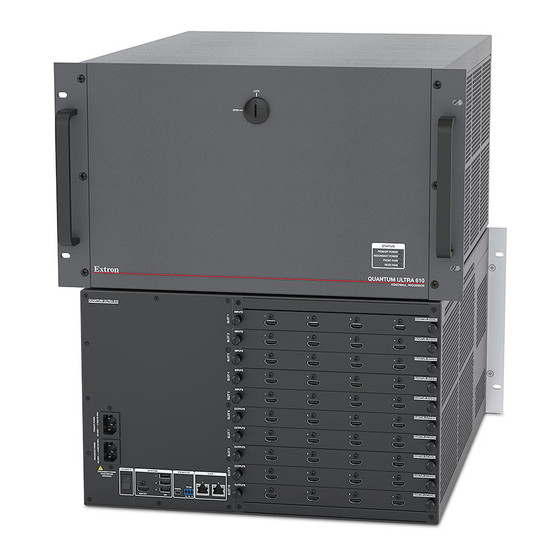
PRIMARY POWER REDUNDANT POWER FRONT FANS REAR FANS QUANTUM ULTRA 610 VIDEO WALL PROCESSOR Front panel lock Status LEDs Figure 6. Quantum Ultra and Ultra II 610 Front Panel Door Quantum Ultra Series Videowall Processing Systems • Installation and Configuration... -
Page 24: Rear Panel Features
POWER switch LAN connectors A and B HDMI OUT system output connector Input and output card slots USB system connectors Figure 7. Quantum Ultra and Ultra II 610 Rear Panel Quantum Ultra Series Videowall Processing Systems • Installation and Configuration... - Page 25 If the unit is on, pressing and holding this switch for approximately 5 seconds powers it down. NOTE: If you are logged into the Quantum Ultra Series device operating system, a momentary press of this switch powers off the device.
- Page 26 USB CONFIG control connector — Connect a computer to this USB connector to enable control of the Quantum Ultra Series device via SIS commands and VCS. RS-232 control connector — Connect a control system or computer to this 3-pole 3.5 mm captive screw connector to enable control of the Quantum Ultra Series...
-
Page 27: Hdmi Lockit Cable Lacing Brackets
Quantum Ultra Connect 84 — Two HDMI input cards and one HDMI output card. On the Quantum Ultra and Ultra II 610 and 305, multiple Quantum Ultra Series chassis can be added to the same project to create very large display arrays. You can remove,... -
Page 28: Card Locations - Quantum Ultra And Ultra Ii 610 And 305
Card Locations — Quantum Ultra and Ultra II 610 and 305 When the Quantum Ultra Series processor is assembled at the factory, the cards are installed according to the following rules: All the input cards are installed in slots above all the output cards in the chassis. -
Page 29: Inputs
Inputs The input cards available for the Quantum Ultra Series include: HDMI (IN4HDMI) — Each card contains four HDMI connectors. • • HDMI 4K PLUS (IN4HDMI 4K PLUS) — (Quantum Ultra II models only) Each card contains four HDMI connectors that support resolutions up to 4096x2160 @ 60 Hz. - Page 30 1.1.1 at 30 Hz 1.1.1 mini cation sizes 1.1.1 for one source 1.1.1 1.1.1 1.1.1 1.1.1 Figure 11. Example of One Input at 1080p, 60 Hz, on One Input Card Quantum Ultra Series Videowall Processing Systems • Installation and Configuration...
- Page 31 1.1.2 1.1.4 mini cation 1.1.2 1.1.4 1.1.2 1.1.4 sizes for one 4K grouped source Figure 14. Example of One 4K Input, 60 Hz, Column or Quad Format, on One Input Card Quantum Ultra Series Videowall Processing Systems • Installation and Configuration...
- Page 32 300 MHz signals, connector 3 is disabled. • HDMI 4K PLUS inputs 1 through 4 — All four inputs accept resolutions with pixel clocks of up to 600 MHz, providing support for 4096x2160 at 60 Hz. Quantum Ultra Series Videowall Processing Systems • Installation and Configuration...
- Page 33 Figure 16. Input Rotation The Quantum Ultra Series HDMI input card can support rotation of two 1920x1080 sources at 60 Hz or one 3840x2160 source at 30 Hz. Additional sources can be rotated, but the processing frame rate is reduced in half to remain within the available bandwidth of the card (see the following examples).
- Page 34 Processed at 30 Hz Four unique mini cation sizes for one source 1.1.1 1.1.1 1.1.1 1.1.1 Figure 18. Example of One Rotated 1080p Input, 60 Hz, on One Input Card Quantum Ultra Series Videowall Processing Systems • Installation and Configuration...
- Page 35 Example 2: One rotated 4K input at 60 Hz applied to one input card Processed at 60 Hz 4 unique minification sizes for one source Processed at 30 Hz 8 unique minification sizes for one source Quantum Ultra Series Videowall Processing Systems • Installation and Configuration...
- Page 36 Installing more IN SMD 100 cards in the chassis increases the total number of streams that can simultaneously be decoded. Hundreds of IP stream definitions can be viewed simultaneously on an output, depending on the number of IN SMD 100 cards installed. Quantum Ultra Series Videowall Processing Systems • Installation and Configuration...
- Page 37 MPEG4 part 2 SP (<10 Mbps) • • MPEG4 part 2 ASP (<10 Mbps) • MPEG4 part 10 (AVC) H.264 BP, MP, HiP up to level 4.2 (<62.5 Mbps, 1 sec) • JPEG over RTP Quantum Ultra Series Videowall Processing Systems • Installation and Configuration...
- Page 38 Unicast RTP over RTSP over HTTP (RTP and RTSP interleaved over TCP on • port 80) — Used where RTP is interleaved with RTSP over HTTP and is used to navigate fire walls that allow HTTP (ports 80 or 8080 are open). Quantum Ultra Series Videowall Processing Systems • Installation and Configuration...
-
Page 39: Outputs
Outputs The Quantum Ultra Series HDMI, HDMI 4K PLUS, and DTP output cards integrate all inputs to be displayed in a layout that you define using the control software (see the VCS Help File for information on using the program to set up displays). They also provide up-scaling of sources. - Page 40 Extron PS 124) to this 2-pole captive screw connector to provide power to receivers connected to any or all of the DTP output connectors on the card. The connected receivers must be classified as Powerable Endpoints (PEP). Quantum Ultra Series Videowall Processing Systems • Installation and Configuration...
- Page 41 Output Channel Configuration Example • HDMI 4K PLUS outputs 1 through 4 — These four outputs generate resolutions with pixel clocks up to 600 MHz, which provides support for 4K at 60 Hz. Quantum Ultra Series Videowall Processing Systems • Installation and Configuration...
- Page 42 Output resolution table The following table shows all the output resolutions and refresh rates supported on Quantum Ultra Series, and which connectors on the output cards support each resolution. Resolution 23.98 Hz 24 Hz 25 Hz 29.97 Hz 30 Hz 50 Hz 59.94 Hz...
- Page 43 • Display number (displays are numbered horizontally on the canvas, • Name of the Quantum Ultra Series device to which the display is connected ( Displays on a videowall can be connected to different processors. • Number of the output card slot on the chassis, followed by the output connector number to which the display is connected ( •...
- Page 44 In the HDMI example in figure 28, the layout utilizes three HDMI output cards (see the diagram in figure 29). OUTPUTS QUANTUM OUT4HDMI OUTPUTS QUANTUM OUT4HDMI OUTPUTS QUANTUM OUT4HDMI Figure 29. Two Output Cards Used in one Canvas Quantum Ultra Series Videowall Processing Systems • Installation and Configuration...
- Page 45 A maximum of 10 canvases can be defined for each Quantum Ultra Series chassis, with each canvas able to support up to 128 window presets associated with it. All canvases (output groups) must be operating at refresh rates that are factors of each other to be properly supported by the HyperLane bus (for example, 60 Hz and 30 Hz or 50 Hz and 25 Hz).
- Page 46 Windows 1 through 16 Windows 17 through 32 Windows 33 through 48 Windows 49 through 64 Figure 32. Example of All Available Windows Distributed Evenly Among the Four Output Channels. Quantum Ultra Series Videowall Processing Systems • Installation and Configuration...
- Page 47 1.10.4 Example 5: One 4K quad output at 60 Hz 1.10.1 1.10.2 1.10.3 1.10.4 Figure 33. Maximum Number of Output Signals Per Output Card at Different Resolutions and Refresh Rates Quantum Ultra Series Videowall Processing Systems • Installation and Configuration...
- Page 48 Figure 35. Output Rotation The Quantum Ultra Series standard HDMI output cards can support rotation of two 1920x1080 outputs at 60 Hz or one 3840x2160 output at 30 Hz. When rotation is enabled, only outputs 2 and 4 are addressable if the resolution pixel clock is less than 165 MHz and only output 4 is addressable if the output resolution is greater than 165 MHz (see the following examples).
-
Page 49: Adjusting For Edge Blending And Mullion Compensation
The VCS enables you to adjust the space around each display to compensate for the mullion (see figure 37 on the next page for an example). See the VCS Help File for instructions on adjusting to compensate for mullion and edge blending. Quantum Ultra Series Videowall Processing Systems • Installation and Configuration... -
Page 50: Connecting To A Network
B port to let you control the Quantum Ultra and to set up videowall applications via the computer. You must use VCS to set up the Quantum Ultra Series chassis. However, you can use SIS to reset the IP address of LAN port A from the default (192.168.254.254) without interacting directly with the embedded operating system interface. -
Page 51: Rs-232 Insertion - Dtp Outputs Only
NOTE: To enable communications between the computer and the processor, the Quantum Ultra Series processor IP address and subnet mask must be compatible as follows: • The subnet mask must be the same for all devices. • The IP addresses must be different, but on the same subnet. -
Page 52: Captive Screw Signal Insertion
Connect a serial cable from the RS-232 and ground pins of the OVER TP connector on the endpoint to the display to be controlled, or connect an IR emitter to the IR and ground pins for IR control of the display. Quantum Ultra Series Videowall Processing Systems • Installation and Configuration... -
Page 53: Selecting The Insertion Method And Rs-232 Protocol
(see the VCS Help File for detailed configuration instructions). NOTE: The insert connections, whether inserted via Ethernet or captive screw connectors, can support up to a 115,200 baud rate. Quantum Ultra Series Videowall Processing Systems • Installation and Configuration... -
Page 54: Expansion Cards
MPO M-M cables are available: 1 meter (3.3 feet) and 10 meters (32.8 feet). Three cables of either length are needed for each pair of output-input expansion cards to be connected together. Quantum Ultra Series Videowall Processing Systems • Installation and Configuration... -
Page 55: Expansion Card Locations
In the example in figure 43, non-expansion input cards ( ) are installed below the Expansion IN card. Non-expansion output cards ( ) follow the input cards. The Expansion OUT card ( ) is in the last slot. Quantum Ultra Series Videowall Processing Systems • Installation and Configuration... -
Page 56: Connecting The Expansion Cards
If desired, connect the LAN B port of all of the chassis to a different network for VNC or RSS sources. Use VCS to configure the videowall for the multi-chassis system (see the VCS Help File for more information). Quantum Ultra Series Videowall Processing Systems • Installation and Configuration... -
Page 57: Operation
The Quantum Ultra Series processor is a host device with an embedded operating system. The Control Panel is a program that resides on the Quantum Ultra Series operating system and enables you to perform various setup and maintenance tasks, such as setting the processor IP address, resetting the device, or updating the firmware. - Page 58 The Control Panel window also contains the following status panels that enable you to observe status and activity of each major component (figure 46): Hardware Status Network Interface Status System Status Firmware Status CPU Usage progress bar Quantum Ultra Series Videowall Processing Systems • Operation...
-
Page 59: Buttons On The Control Panel
Loading Image Files You can upload image files from an external USB drive to the Quantum Ultra Series processor to be displayed as sources in windows and incorporated into presets. You can also upload image files using VCS (see the VCS Help File for instructions). - Page 60 Figure 48. USB Flash Drive Containing Picture Files On the USB drive, locate the image files to be loaded to the Quantum Ultra Series device and drag or copy them to the Pictures folder on the unit D: Data drive.
-
Page 61: Updating The Password
Click the Enter button at the bottom of the Change Password window. The following prompt opens, informing you that the unit will reboot and enable write protection for the new password to take effect. Figure 51. Password Reboot Prompt Click OK to reboot. Quantum Ultra Series Videowall Processing Systems • Operation... -
Page 62: Updating Firmware
Updating Firmware If it becomes necessary to update the firmware on your Quantum Ultra Series processor, www.extron.com you can obtain new firmware at and upload it to the unit. Downloading a Firmware File On the Extron website, hover the mouse pointer over the... -
Page 63: Uploading A Firmware File
On the Control Panel window, click the Service Mode button (see figure 47, on page 51). Copy the firmware file from the USB drive to the root directory of the D: drive. On the Control Panel window, click the Update Firmware button ( Quantum Ultra Series Videowall Processing Systems • Operation... - Page 64 On the next screen, click the Browse button and locate the new firmware file. Double-click on the firmware file or select it and click Open. The Quantum Ultra firmware file must have a .gpg extension. Figure 56. Selecting the Firmware File on the D: Drive Quantum Ultra Series Videowall Processing Systems • Operation...
- Page 65 (see figure 58, ), while a progress bar ( ) at the bottom of the screen lets you know approximately how much time remains for the installation. Figure 58. Installation Progress Screen Quantum Ultra Series Videowall Processing Systems • Operation...
-
Page 66: Modifying Network Settings From The Control Panel
To change the IP addresses of the LAN A and LAN B ports: On the Control Panel window, click the Network Settings button (see figure 47, on page 51. The Network Settings window opens. Figure 60. Network Settings for LAN A Port Quantum Ultra Series Videowall Processing Systems • Operation... -
Page 67: Resetting The Device From The Control Panel
If desired, enter a name of 1 to 15 characters for your Quantum Ultra Series processor in the Device Name field (see figure 60, on the previous page). Only letters, numbers, and the hyphen (-) can be used in this name. -
Page 68: Service Mode
Click OK. The unit reboots and resets. Service Mode In service mode, you can access the Quantum Ultra Series C: and D: drives as well as the operating system Control Panel. To enter service mode: On the Quantum Ultra Control Panel main window, click Service Mode (see figure 47,... -
Page 69: Disabling And Enabling Write Protection
Restart Prompt for Enabling Write Protection Click OK. The unit reboots and Write Protection is enabled. Shutting Down the Device If required, use one of the following methods to shut down the Quantum Ultra Series device: • When a keyboard, mouse, and monitor are attached, the processor can be shut down via the Control Panel. -
Page 70: Remote Configuration And Control
Configuration and Control This section describes the methods by which the Quantum Ultra Series can be configured and controlled remotely: the Extron Simple Instruction Set (SIS) commands and the Videowall Configuration Software (VCS). It describes the available SIS commands and how to enter them, as well as providing instructions for obtaining and accessing VCS. -
Page 71: Processor-Initiated Messages
Processor-initiated Messages When a local event such as a software selection or adjustment takes place, the Quantum Ultra Series processor responds by sending a message to the host. No response is required from the host. Examples of messages initiated by the processor are:... -
Page 72: Symbol Definitions
= Image file (.bmp, .jpg, .tif, or .png) = Window selection — 1 through 999 = All windows (for window mute only) Response is three digits with leading zeros. Quantum Ultra Series Videowall Processing Systems • Remote Configuration and Control... - Page 73 Response is three digits padded with zeros. = Input preset number — through Response is three digits padded with zeros. = Window mute = Off (unmute) (default) = On (mute window) Quantum Ultra Series Videowall Processing Systems • Remote Configuration and Control...
- Page 74 Leading zeros in the octets are optional in setting values, suppressed in returned values. 00-05-A6-xx-xx-xx X11* = Hardware (MAC) address ( X11( = Subnet mask ( Leading zeros in the octets are optional in setting values, suppressed in returned values. Quantum Ultra Series Videowall Processing Systems • Remote Configuration and Control...
- Page 75 = Verbose mode and tagged response for queries NOTES: • In verbose response mode, the Quantum Ultra Series device returns unsolicited responses for value and setting changes that may result from a signal change, or a setting adjustment made via another interface.
-
Page 76: Command And Response Table For Sis Commands
Name or text label (for inputs) — Up to 32 characters. Invalid characters: \ / : * ? , > |. X8$ = Input resolution support: 0 = Up to 165 MHz, 1 = Up to 300 MHz Quantum Ultra Series Videowall Processing Systems • Remote Configuration and Control... - Page 77 * green * blue} RGB color value for source text string or text background — 0-255, in the format { First value = red, second value = green, third value = blue. Quantum Ultra Series Videowall Processing Systems • Remote Configuration and Control...
- Page 78 Window mute: 0 = Unmute (default), 1 = Mute window. Window priority position — 001 through 999. Response is three digits padded with zeros. 001 = Front. Text size in points — 8 through 251 Quantum Ultra Series Videowall Processing Systems • Remote Configuration and Control...
- Page 79 Response is six digits with leading + or -, padded with zeros. X1& Horizontal and vertical size (Limits depend on input or output resolutions.) Response is six digits, padded with zeros. Quantum Ultra Series Videowall Processing Systems • Remote Configuration and Control...
- Page 80 Response is six digits with leading + or -, padded with zeros. X1& Horizontal and vertical size. (Limits depend on input or output resolutions.) Response is six digits, padded with zeros. Quantum Ultra Series Videowall Processing Systems • Remote Configuration and Control...
- Page 81 Name or text label for window presets — Up to 32 characters. Invalid characters: Window preset number — 1 through 128. Response is three digits padded with zeros. Input preset number: 1 through 128. Response is three digits padded with zeros. Quantum Ultra Series Videowall Processing Systems • Remote Configuration and Control...
- Page 82 Video signal status: 0 = Video signal not detected, 1 = Video signal detected. Power save status: 0 = off (full power mode, default), 1 = power save on. Window border style number: 000 through 127. 000 = No border. Quantum Ultra Series Videowall Processing Systems • Remote Configuration and Control...
- Page 83 This command also removes the initial factory-configured serial number password, and resets it to extron. Quantum Ultra Series Videowall Processing Systems • Remote Configuration and Control...
- Page 84 Vertical frequency: Response format is three digits with leading zeros and one decimal place. Window mute: 0 = Off (unmute) (default), 1 = On (mute window) Input resolution: Horizontal and vertical dimensions. Quantum Ultra Series Videowall Processing Systems • Remote Configuration and Control...
- Page 85 2 = Sink detected, output encrypted with HDCP (plugged and encrypted) Chassis order number in an expansion system: 1 = Chassis 1, 2 = Chassis 2, 3 = Chassis 3, 4 = Chassis 4, 5 = Chassis 5 Quantum Ultra Series Videowall Processing Systems • Remote Configuration and Control...
- Page 86 X12& Set date and time format: MM/DD/YY-HH:MM:SS Example: 08/17/21-13:51:30 YYYY HH:MM:SS View date and time format: {day of the week}, • • • Example: Tue, 17 Aug 2021 13:53:58 Quantum Ultra Series Videowall Processing Systems • Remote Configuration and Control...
- Page 87 Network interface: 1 = LAN A port, 2 = LAN B port X17& Prefix representing subnet mask bits (subnet mask value in CISG commands). Default = /24, which represents the default subnet mask, 255.255.255.0. Quantum Ultra Series Videowall Processing Systems • Remote Configuration and Control...
- Page 88 **** password, is omitted from the response. KEY: X13# Administrator or user password, 128 characters maximum. / \ | * and space characters are not allowed. Passwords are case-sensitive. Quantum Ultra Series Videowall Processing Systems • Remote Configuration and Control...
-
Page 89: Videowall Configuration Software (Vcs) Program
Videowall Configuration Software (VCS) Program The Extron VCS program is a PC-based program for the Quantum Ultra Series that provides a convenient way to configure the videowall. System configuration is broken down into logical tasks, including output and wall configuration, source setup, preset design, and EDID Minder. - Page 90 By default, the installation places the program files at: C:\Program Files (x86)\Extron\Extron VCS. If there is not already an Extron folder in your Program Files x86 folder, the installation program creates it as well. Quantum Ultra Series Videowall Processing Systems • Remote Configuration and Control...
-
Page 91: Starting The Configuration Program
) to open the Create New Project screen. Figure 70. VCS New Project Screen Select the radio button for your Quantum Ultra Series device (Quantum Ultra or Quantum Ultra Connect, NOTE: You cannot proceed without selecting a device type. Quantum Ultra Series Videowall Processing Systems • Remote Configuration and Control... - Page 92 VCS searches for devices that are connected to the network and are the type of device selected in step 3. The Connection screen displays a list of detected Quantum Ultra Series devices (see figure 71 Figure 71.
- Page 93 Figure 74. Manually Add Device Window In the IP Address field, enter the address of the Quantum Ultra Series device to be connected (see figure 74, If necessary, select the Quantum Ultra Series device type from the Device Type drop-down menu ( Click Add.
- Page 94 ) to display the Communication button (see figure 77, Settings dialog box. Figure 77. Device Details Screen For detailed instructions on using VCS to configure the videowall, see the VCS Help File. Quantum Ultra Series Videowall Processing Systems • Remote Configuration and Control...
-
Page 95: Starting The Vcs Program With Expansion Cards
A prompt window appears, indicating that the initial configuration is complete and that the system will reboot. Click OK on the prompt to close it. The reboot starts automatically and takes a few minutes to complete. Quantum Ultra Series Videowall Processing Systems • Remote Configuration and Control... - Page 96 Click this button to display a drop-down list of the IP addresses of all the chassis in the chain (see figure 81, Figure 81. Expansion Details List in the System Devices Panel Configure the videowall (see the VCS Help File). Quantum Ultra Series Videowall Processing Systems • Remote Configuration and Control...
- Page 97 NOTE: If the Quantum Ultra Expansion line does not appear on the connection screen, add the primary device manually (see If you do not see your device in the Select Device(s) to Add panel on page 85). Quantum Ultra Series Videowall Processing Systems • Remote Configuration and Control...
- Page 98 Files (Retains TCP/IP Settings) (the second radio button). Click Reset. The system reboots. After approximately 2 minutes, the expansion devices appear listed separately in the device discovery panel, as shown in figure 78 on page 87. Quantum Ultra Series Videowall Processing Systems • Remote Configuration and Control...
-
Page 99: Maintenance
Insert a coin, such as a penny, in the slot on the front panel lock and rotate it one quarter turn counterclockwise, until the dot above the slot faces Open. LOCK LOCK OPEN OPEN Figure 84. Front Panel Door Lock Quantum Ultra Series Videowall Processing Systems • Maintenance — Quantum Ultra 610 Only... - Page 100 • Les vis doivent être serrées avec un tournevis après la première installation et l’accès postérieur au panneau. NOTE: The thumbscrews cannot be removed completely. Quantum Ultra Series Videowall Processing Systems • Maintenance — Quantum Ultra 610 Only...
-
Page 101: Front Panel Contents
Primary power supply C: drive Redundant power supply D: drive Protective cover panel System Board Computer (SBC) (Quantum Ultra 610 only) Figure 86. Front Panels (Behind the Door) Quantum Ultra Series Videowall Processing Systems • Maintenance — Quantum Ultra 610 Only... -
Page 102: Replacing Input And Output Cards
D:) and the SBC, which runs the Quantum Ultra Series firmware. Replacing Input and Output Cards When you place an order for a Quantum Ultra Series processor, you specify how many input and output cards are loaded when the product is shipped. However, if your application changes, you may want to purchase additional cards from Extron and replace one or more of the original cards. - Page 103 NOTE: The card is not completely in place until you hear or feel it snap into the connector at the end of the card. If you do not feel it snap into position, press on it more firmly until you do. Quantum Ultra Series Videowall Processing Systems • Maintenance — Quantum Ultra 610 Only...
-
Page 104: And Ultra Ii 610
This section describes the procedure for replacing the primary power supply. If the redundant power supply needs to be replaced, some additional steps are required (see Replacing the Redundant Power Supply on page 101). Quantum Ultra Series Videowall Processing Systems • Maintenance — Quantum Ultra 610 Only... - Page 105 Rotate the lever to the right ( ) until it is in a horizontal position, parallel to the top and bottom of the unit. Quantum Ultra Series Videowall Processing Systems • Maintenance — Quantum Ultra 610 Only...
- Page 106 Slide the power supply unit to the right. Slide the unit out. Figure 90. Rotating the Latch and Sliding the Power Supply to the Right and Out (Quantum Ultra 610) Quantum Ultra Series Videowall Processing Systems • Maintenance — Quantum Ultra 610 Only...
- Page 107 Slide the new power supply into the empty slot vacated by the old power supply, until its back panel is flat against the back wall of the power supply compartment. Quantum Ultra Series Videowall Processing Systems • Maintenance — Quantum Ultra 610 Only...
- Page 108 Slide the round end of the lever ( 2 ) between the two pegs ( 1 ) when installing a power supply. Figure 93. Positioning the Lever between the Two Pegs on the Chassis Quantum Ultra Series Videowall Processing Systems • HTML Operation...
-
Page 109: Replacing The Redundant Power Supply
(see figure 95). Retain the back plate and screws to reattach the strip in step 6. Remove three screws. Figure 95. Removing the Metal Strip from the Failed Power Supply Back Panel Quantum Ultra Series Videowall Processing Systems • Maintenance — Quantum Ultra 610 Only... -
Page 110: Replacing The Power Supply Front Fan - Quantum Ultra 610 Only
Use a screwdriver to loosen the two thumbscrews on the cover panel and remove the panel (see figure 96). Loosen the thumbscrews. Take off the panel. Figure 96. Removing the Cover Panel Quantum Ultra Series Videowall Processing Systems • Maintenance — Quantum Ultra 610 Only... - Page 111 Les vis doivent être serrées avec un tournevis après la première installation et l’accès postérieur au panneau. Disconnect the small fan cables ( Cables Loosen the thumbscrew. Disconnect the cables. Figure 97. Detaching the Front Fan Quantum Ultra Series Videowall Processing Systems • Maintenance — Quantum Ultra 610 Only...
- Page 112 The replacement fan has two tabs on the back (see figure 99). These tabs fit into two slots in the back of the fan compartment of the chassis (see figure 100). Tabs Figure 99. Tabs on the Front Fan Quantum Ultra Series Videowall Processing Systems • Maintenance — Quantum Ultra 610 Only...
- Page 113 1 1 1 Figure 101. Inserting the Replacement Fan When the fan unit is in place, use a screwdriver to tighten the thumbscrew. Connect the two fan cables. Quantum Ultra Series Videowall Processing Systems • Maintenance — Quantum Ultra 610 Only...
-
Page 114: Replacing A Disk Drive - Quantum Ultra And Ultra Ii 610
Picture files can be downloaded from the D drive of the unit using the System HDMI and USB connections. Shut down the unit and disconnect the power. Quantum Ultra Series Videowall Processing Systems • Maintenance — Quantum Ultra 610 Only... - Page 115 Les vis doivent être serrées avec un tournevis après la première installation et l’accès postérieur au panneau. Grasp the thumbscrew firmly and pull the drive straight toward you until it is free (see figure 103, Quantum Ultra Series Videowall Processing Systems • Maintenance — Quantum Ultra 610 Only...
- Page 116 Quantum Ultra VCS Help File), or SIS (see Set IP address on page 79). Use the latest project file to connect to the device via VCS and confirm the system is operational. Quantum Ultra Series Videowall Processing Systems • Maintenance — Quantum Ultra 610 Only...
-
Page 117: Replacing The System Board Computer
Unplug the lower fan cable from the 3-pin connector at the right front corner of the SBC assembly (see figure 105). Fan Cable Figure 105. Unplugging the Fan Cable Quantum Ultra Series Videowall Processing Systems • Maintenance — Quantum Ultra 610 Only... - Page 118 Pull the handle on the SBC ( ) toward you until the assembly is free of the chassis. Loosen the thumbscrews (2). Figure 106. Removing the SBC Assembly Quantum Ultra Series Videowall Processing Systems • Maintenance — Quantum Ultra 610 Only...
-
Page 119: Installing A New Sbc Assembly
Reinstall the hard drives on the SBC assembly (see Replacing a Disk Drive — Quantum Ultra and Ultra II 610 on page 106). Power the system back on. Quantum Ultra Series Videowall Processing Systems • Maintenance — Quantum Ultra 610 Only... -
Page 120: Reference
Please contact Extron if you have any questions about the guidelines outlined in this section or if you have a question about cleaning a specific Extron product. Quantum Ultra Series Videowall Processing Systems • Reference 112... -
Page 121: Cleaning Fiber Optic Connectors And Cables
Ne jamais inspecter ni regarder le bout des fibres raccordées lorsque les câbles • sont connectés aux équipements car le rayonnement laser invisible peut entraîner des lésions oculaires. Quantum Ultra Series Videowall Processing Systems • Reference... -
Page 122: Mounting The Quantum Ultra Series
Mounting the Quantum Ultra Series The Quantum Ultra Series processor can be placed on a tabletop or mounted in a rack (recommended). CAUTION: The Quantum Ultra 610 and Ultra II 610 chassis is very heavy. When it is fully populated with input and output cards, its weight can be up to 87 lbs (39.5 kg). -
Page 123: Rack Mounting Requirements
Do not stand other units directly on top of the processor when it is rack mounted because this can overload the mountings. • N’installez pas d’autres produits directement au-dessus du processeur lorsque celui-ci est monté en rack : cela risquerait de surcharger les éléments de montage. Quantum Ultra Series Videowall Processing Systems • Reference... - Page 124 Rack Mounting the Quantum Ultra or Ultra II 610 ATTENTION: • Because of the weight of the Quantum Ultra Series processor, you must provide additional support for the unit from the back. • Compte tenu du poids du processeur Quantum Ultra Series, vous devez fournir plus de capacités de support à...
- Page 125 Extron Warranty Extron warrants this product against defects in materials and workmanship for a period of three years from the date of purchase. In the event of malfunction during the warranty period attributable directly to faulty workmanship and/ or materials, Extron will, at its option, repair or replace said products or components, to whatever extent it shall deem necessary to restore said product to proper operating condition, provided that it is returned within the warranty period, with proof of purchase and description of malfunction to: USA, Canada, South America,...