
Related Manuals for Juniper MX10


Summary of Contents for Juniper MX10
- Page 1 MX5, MX10, MX40, and MX80 3D Universal Edge Router Hardware Guide Modified: 2017-08-04 Copyright © 2017, Juniper Networks, Inc.
- Page 2 END USER LICENSE AGREEMENT The Juniper Networks product that is the subject of this technical documentation consists of (or is intended for use with) Juniper Networks software. Use of such software is subject to the terms and conditions of the End User License Agreement (“EULA”) posted at http://www.juniper.net/support/eula/.
-
Page 3: Table Of Contents
MX5, MX10, MX40, and MX80 Router Overview ......3 MX5, MX10, MX40, and MX80 Router Models ......5 MX5, MX10, MX40, and MX80 Hardware Components and CLI Terminology . - Page 4 DC Power Supply Description ........37 MX5, MX10, MX40, and MX80 Power Supply LED ......38...
- Page 5 Tools and Parts Required to Unpack MX5, MX10, MX40, and MX80 Routers ..75 Unpacking MX5, MX10, MX40, and MX80 Routers ......75 Verifying the MX5, MX10, MX40, and MX80 Routers Parts Received .
- Page 6 Replacing Line Card Components ........113 Installing an MX5, MX10, MX40, and MX80 MIC ......113 Installing an MX10, MX40, MX80, and MX104 Dual-Wide MIC .
- Page 7 Maintaining the MX5, MX10, MX40, and MX80 Fan Tray ....158 Maintaining the MX5, MX10, MX40, and MX80 MICs ..... . 159 Maintaining Cables That Connect to MX5, MX10, MX40, and MX80 MICs .
- Page 8 MX5, MX10, MX40, and MX80 Fan Tray Serial Number Label ....179 MX5, MX10, MX40, and MX80 MIC Serial Number Label ....180 MX5, MX10, MX40, and MX80 Power Supply Serial Number Label .
- Page 9 Compliance Statements for NEBS ........232 Compliance Statements for Acoustic Noise for MX5, MX10, MX40, and MX80 Routers .
- Page 10 MX5, MX10, MX40, and MX80 3D Universal Edge Router Hardware Guide Copyright © 2017, Juniper Networks, Inc.
-
Page 11: List Of Figures
Figure 6: Front View of the MX10 Router ....... . . - Page 12 Chapter 14 Installing the MX5, MX10, MX40, and MX80 Routers ....83 Figure 33: Installing the Front-Mounted Router in the Rack ....86 Figure 34: Installing the Center-Mounted Router in the Rack .
- Page 13 General Safety Guidelines and Warnings ......189 Figure 77: ESD Points on the MX5, MX10, MX40, and MX80 Chassis ..195 Figure 78: Placing a Component into an Electrostatic Bag .
- Page 14 MX5, MX10, MX40, and MX80 3D Universal Edge Router Hardware Guide Copyright © 2017, Juniper Networks, Inc.
- Page 15 Table 4: MX10 Router Models ........
- Page 16 Chapter 12 Unpacking the MX5, MX10, MX40, and MX80 Routers ....75 Table 38: Parts List for a Fully Configured Router ......76 Table 39: Accessory Box Parts List .
-
Page 17: About The Documentation
® To obtain the most current version of all Juniper Networks technical documentation, see the product documentation page on the Juniper Networks website at http://www.juniper.net/techpubs/ If the information in the latest release notes differs from the information in the documentation, follow the product Release Notes. -
Page 18: Table 1: Notice Icons
MX5, MX10, MX40, and MX80 3D Universal Edge Router Hardware Guide Table 1: Notice Icons Icon Meaning Description Informational note Indicates important features or instructions. Caution Indicates a situation that might result in loss of data or hardware damage. Warning Alerts you to the risk of personal injury or death. -
Page 19: Documentation Feedback
We encourage you to provide feedback, comments, and suggestions so that we can improve the documentation. You can provide feedback by using either of the following methods: Online feedback rating system—On any page of the Juniper Networks TechLibrary site , simply click the stars to rate the content, http://www.juniper.net/techpubs/index.html and use the pop-up form to provide us with information about your experience. -
Page 20: Requesting Technical Support
MX5, MX10, MX40, and MX80 3D Universal Edge Router Hardware Guide E-mail—Send your comments to . Include the document techpubs-comments@juniper.net or topic name, URL or page number, and software version (if applicable). Requesting Technical Support Technical product support is available through the Juniper Networks Technical Assistance Center (JTAC). - Page 21 About the Documentation For international or direct-dial options in countries without toll-free numbers, see http://www.juniper.net/support/requesting-support.html Copyright © 2017, Juniper Networks, Inc.
- Page 22 MX5, MX10, MX40, and MX80 3D Universal Edge Router Hardware Guide xxii Copyright © 2017, Juniper Networks, Inc.
-
Page 23: Overview
Chassis Components and Descriptions on page 9 Cooling System Components and Descriptions on page 19 Host Subsystem Components and Descriptions on page 21 Line Card Components and Descriptions on page 23 Power System Components and Descriptions on page 35 Copyright © 2017, Juniper Networks, Inc. - Page 24 MX5, MX10, MX40, and MX80 3D Universal Edge Router Hardware Guide Copyright © 2017, Juniper Networks, Inc.
-
Page 25: System Overview
MX5, MX10, MX40, and MX80 Router Overview on page 3 MX5, MX10, MX40, and MX80 Router Models on page 5 MX5, MX10, MX40, and MX80 Hardware Components and CLI Terminology on page 7 MX5, MX10, MX40, and MX80 Router Overview... -
Page 26: Figure 1: Mx5 Router
MX5, MX10, MX40, and MX80 3D Universal Edge Router Hardware Guide MX5 router: Allows usage of the MIC slot labeled , which comes prepopulated 1/MIC 0 with the Gigabit Ethernet MIC with SFP. Figure 1: MX5 Router 20-port Gigabit Ethernet MIC... -
Page 27: Mx5, Mx10, Mx40, And Mx80 Router Models
A fixed version of the MX80 router (model number: MX80-48T) has 48 fixed 10/100/1000Base-T RJ45 ports in place of the MIC slots. For a list of MICs supported on the MX5, MX10, MX40, and modular MX80 routers, see “MICs Supported by MX Series Routers” on page 26... -
Page 28: Table 4: Mx10 Router Models
MX5, MX10, MX40, and MX80 3D Universal Edge Router Hardware Guide Table 4: MX10 Router Models Model Number Description MX10-T-DC DC chassis MX10-T-AC AC chassis Table 5 on page 6 lists the different MX40 router models available. Table 5: MX40 Router Models... -
Page 29: Mx5, Mx10, Mx40, And Mx80 Hardware Components And Cli Terminology
MX5, MX10, MX40, and MX80 Hardware Components and CLI Terminology The MX5, MX10, MX40, and MX80 routers support the components in Table 7 on page listed in alphabetic order. Table 7: MX5, MX10, MX40, and MX80 Routers Hardware Components and CLI Terminology Component Hardware Model Number CLI Name... - Page 30 MX5, MX10, MX40, and MX80 3D Universal Edge Router Hardware Guide Copyright © 2017, Juniper Networks, Inc.
-
Page 31: Chassis Components And Descriptions
MX5, MX10, MX40, and MX80 Cable Management Bracket Description on page 12 MX5, MX10, MX40, and MX80 Front Panel Description on page 13 Alarm LEDs on the MX5, MX10, MX40, and MX80 Front Panel on page 15 Component LEDs on the MX5, MX10, MX40, and MX80 Front Panel on page 15... -
Page 32: Figure 6: Front View Of The Mx10 Router
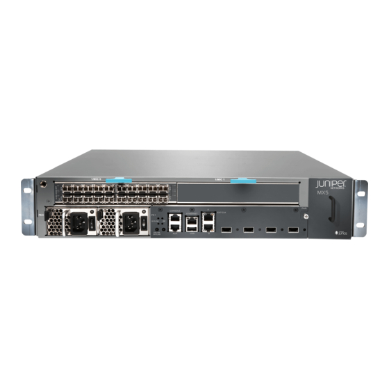
MX5, MX10, MX40, and MX80 3D Universal Edge Router Hardware Guide Figure 6: Front View of the MX10 Router MIC slots point CONS OLE PS 1 ETHE RNET M X1 0- T EXT CLK SYS OK ONLIN E LINK OFFLI NE... -
Page 33: Mx5, Mx10, Mx40, And Mx80 Baseboard Description
Chapter 2: Chassis Components and Descriptions Figure 9: Front View of the MX80 Router (Modular Chassis) MIC slots point AC power supplies Front panel Figure 10: Rear View of the MX5, MX10, MX40, and MX80 Routers Protective slot earthing terminal point Clock... -
Page 34: Baseboard Components
MX5, MX10, MX40, and MX80 3D Universal Edge Router Hardware Guide The baseboard provides the following functions: Powers on and powers off MICs Controls clocking, system resets, and booting Monitors and controls system functions, including fan speed, board power status, PDM... -
Page 35: Mx5, Mx10, Mx40, And Mx80 Front Panel Description
Connecting MX5, MX10, MX40, and MX80 Routers to Management Devices on page 97 Connecting Interface Cables to MX5, MX10, MX40, and MX80 Routers on page 99 Maintaining Cables That Connect to MX5, MX10, MX40, and MX80 MICs on page 160 MX5, MX10, MX40, and MX80 Front Panel Description The front panel is located on the front of the router and allows you to view status and troubleshooting information at a glance. -
Page 36: Front Panel Components
MX5, MX10, MX40, and MX80 3D Universal Edge Router Hardware Guide Figure 13: Front Panel on the Modular MX5, MX10, MX40, and MX80 Routers Alarm Routing Console Ethernet LEDs Engine port port System status ONLINE/ OFFLINE ONLINE/ Auxiliary Clock Reset... -
Page 37: Alarm Leds On The Mx5, Mx10, Mx40, And Mx80 Front Panel
Figure 14: USB Memory Device in an MX5, MX10, MX40, and MX80 Router USB Memory card Related Alarm LEDs on the MX5, MX10, MX40, and MX80 Front Panel on page 15 Documentation Component LEDs on the MX5, MX10, MX40, and MX80 Front Panel on page 15 Alarm LEDs on the MX5, MX10, MX40, and MX80 Front Panel Two alarm LEDs are located at the left of the front panel. -
Page 38: Link Leds On The Front Panel
— Routing Engine is transitioning online. Related Alarm LEDs on the MX5, MX10, MX40, and MX80 Front Panel on page 15 Documentation Troubleshooting Resources for MX5, MX10, MX40, and MX80 Routers on page 167 Troubleshooting the MX5, MX10, MX40, and MX80 Fan Tray on page 169 Troubleshooting the MX5, MX10, MX40, and MX80 MICs on page 170 Copyright ©... - Page 39 Chapter 2: Chassis Components and Descriptions Troubleshooting the MX5, MX10, MX40, and MX80 Power Supplies on page 170 Copyright © 2017, Juniper Networks, Inc.
- Page 40 MX5, MX10, MX40, and MX80 3D Universal Edge Router Hardware Guide Copyright © 2017, Juniper Networks, Inc.
-
Page 41: Cooling System Components And Descriptions
CHAPTER 3 Cooling System Components and Descriptions MX5, MX10, MX40, and MX80 Cooling System Description on page 19 MX5, MX10, MX40, and MX80 Cooling System Description The cooling system consists of the following components: Fan tray Air filter The cooling system components work together to keep all router components within the... -
Page 42: Figure 16: Fan Tray And Air Filter
Thumbscrew Handle Related Maintaining the MX5, MX10, MX40, and MX80 Air Filter on page 158 Documentation Maintaining the MX5, MX10, MX40, and MX80 Fan Tray on page 158 Troubleshooting the MX5, MX10, MX40, and MX80 Fan Tray on page 169 Replacing an MX5, MX10, MX40, and MX80 Fan Tray on page 111 Copyright ©... -
Page 43: Host Subsystem Components And Descriptions
MX5, MX10, MX40, and MX80 Routing Engine LED on page 21 MX5, MX10, MX40, and MX80 Routing Engine Description The Routing Engine is built-in on the MX5, MX10, MX40, and MX80 baseboard and cannot be replaced. The Routing Engine consists of the following components: Processor—Runs Junos OS to maintain the router's routing tables and routing protocols. - Page 44 MX5, MX10, MX40, and MX80 3D Universal Edge Router Hardware Guide Copyright © 2017, Juniper Networks, Inc.
-
Page 45: Line Card Components And Descriptions
On the fixed MX80 chassis, the MICs come preinstalled and cannot be replaced. On the modular MX5, MX10, MX40, and MX80 chassis, you can install a variety of MICs in the two front slots of the router, and the optional Multiservices MIC can be installed in the rear slot. -
Page 46: Front-Pluggable Mics
MX5, MX10, MX40, and MX80 3D Universal Edge Router Hardware Guide Front-Pluggable MICs You can install and remove MICs in the MX5, MX10, MX40, and modular MX80 chassis. The MIC slots are labeled 1/MIC 0 1/MIC 1 . Each MIC slot has an ejector handle located above the MIC slot. -
Page 47: Built-In Tri-Rate Mic
Link LED, one green per port. For more information, see Table 16 on page Related MX5, MX10, MX40, and MX80 Modular Interface Card LEDs on page 33 Documentation Maintaining the MX5, MX10, MX40, and MX80 MICs on page 159 Troubleshooting the MX5, MX10, MX40, and MX80 MICs on page 170 Replacing an MX5, MX10, MX40, and MX80 MIC on page 118 Copyright ©... -
Page 48: Mics Supported By Mx Series Routers
MX480, MX960, MX2008, MX2010, and MX2020 routers. Table 13 on page 28 lists the first supported Junos OS release for MICs on MX5, MX10, MX40, MX80, and MX104 routers. Table 12: MICs Supported by MX240, MX480, MX960, MX2008, MX2010, and MX2020 Routers... - Page 49 11.4 15.1F7 12.3 12.3 OC3/STM1 (Multi-Rate) MICs with SFP Channelized SONET/SDH MIC-3D-8CHOC3-4CHOC12 11.4 15.1F7 12.3 12.3 OC3/STM1 (Multi-Rate) MICs with SFP Channelized OC3/STM1 MIC-3D-4COC3-1COC12-CE 12.2 15.1F7 12.3 12.3 (Multi-Rate) Circuit Emulation MIC with SFP Copyright © 2017, Juniper Networks, Inc.
-
Page 50: Table 13: Mics Supported By Mx5, Mx10, Mx40, Mx80, And Mx104 Routers
SONET/SDH OC192/STM64 MIC MIC-3D-1OC192-XFP 12.2 15.1F7 12.3 12.3 with XFP Table 13: MICs Supported by MX5, MX10, MX40, MX80, and MX104 Routers MIC Name MIC Model Number P o r t s MX10 MX40 MX80 M X 1 0 4... - Page 51 Chapter 5: Line Card Components and Descriptions Table 13: MICs Supported by MX5, MX10, MX40, MX80, and MX104 Routers (continued) MIC Name MIC Model Number P o r t s MX10 MX40 MX80 M X 1 0 4 Gigabit Ethernet MIC with SFP MIC-3D-20GE-SFP-EH –...
-
Page 52: Mx5, Mx10, Mx40, And Mx80 Port And Interface Numbering
For a complete list of media types, see Interface Naming Overview in the MX Series Interface Module Reference guide. fpc—Slot in which the MPC is installed. On the MX5, MX10, MX40, and MX80 routers, the MPCs are built into the chassis and are represented in the CLI as either... -
Page 53: Figure 18: Mx5, Mx10, Mx40, And Mx80 Interface Port Mapping
MX Series Interface Module Reference Table 14 on page 31 summarizes the relationship between the components and the interface names. Table 14: MX5, MX10, MX40, and MX80 Components and Their Interface Names Component Name in the CLI Interface Names Built-in 4-port 10-Gigabit Ethernet MIC... -
Page 54: Port And Interface Numbering On Mx80-48T Routers
MX5, MX10, MX40, and MX80 3D Universal Edge Router Hardware Guide Table 14: MX5, MX10, MX40, and MX80 Components and Their Interface Names (continued) Component Name in the CLI Interface Names Multiservices MIC installed in the rear of the MS-MIC-16G... -
Page 55: Mx5, Mx10, Mx40, And Mx80 Modular Interface Card Leds
Related MX5, MX10, MX40, and MX80 Hardware Components and CLI Terminology on page 7 Documentation MX5, MX10, MX40, and MX80 Modular Interface Card Description on page 23 MICs Supported by MX Series Routers on page 26 MX5, MX10, MX40, and MX80 Modular Interface Card LEDs The fixed 10-Gigabit Ethernet Modular Interface Card (MIC) has link LEDs located on the front panel. - Page 56 MX5, MX10, MX40, and MX80 3D Universal Edge Router Hardware Guide Copyright © 2017, Juniper Networks, Inc.
-
Page 57: Power System Components And Descriptions
MX5, MX10, MX40, and MX80 Power Supply LED on page 38 MX5, MX10, MX40, and MX80 Power System Description The MX5, MX10, MX40, and MX80 routers use either AC or DC power supplies (see Figure 20 on page 36 Figure 21 on page 36). -
Page 58: Ac Power Supply Description
MX5, MX10, MX40, and MX80 3D Universal Edge Router Hardware Guide Figure 20: AC Power Supplies Installed in an MX5, MX10, MX40, and MX80 Router AC power supplies Figure 21: DC Power Supplies Installed in an MX5, MX10, MX40, and MX80... -
Page 59: Dc Power Supply Description
MX5, MX10, MX40, and MX80 Power Supply LED on page 38 Documentation Maintaining the MX5, MX10, MX40, and MX80 Power Supplies on page 161 Troubleshooting the MX5, MX10, MX40, and MX80 Power Supplies on page 170 Copyright © 2017, Juniper Networks, Inc. -
Page 60: Mx5, Mx10, Mx40, And Mx80 Power Supply Led
MX5, MX10, MX40, and MX80 3D Universal Edge Router Hardware Guide MX5, MX10, MX40, and MX80 Routers AC Power Specifications on page 53 MX5, MX10, MX40, and MX80 Routers DC Power Specifications on page 59 MX5, MX10, MX40, and MX80 Power Supply LED Each power supply has a bi-color status LED located above the power switch on the power supply. -
Page 61: Site Planning, Preparation, And Specifications
Preparation Overview on page 41 AC Power Specifications and Requirements on page 53 DC Power Specifications and Requirements on page 59 Transceiver and Cable Specifications on page 65 Port Cable and Pinout Specifications on page 71 Copyright © 2017, Juniper Networks, Inc. - Page 62 MX5, MX10, MX40, and MX80 3D Universal Edge Router Hardware Guide Copyright © 2017, Juniper Networks, Inc.
-
Page 63: Preparation Overview
CHAPTER 7 Preparation Overview MX5, MX10, MX40, and MX80 Routers Physical Specifications on page 41 MX5, MX10, MX40, and MX80 Router Environmental Specifications on page 42 MX5, MX10, MX40, and MX80 Router Grounding Specifications on page 43 MX5, MX10, MX40, and MX80 Site Preparation Checklist on page 44... -
Page 64: Mx5, Mx10, Mx40, And Mx80 Router Environmental Specifications
Articles 110-16, 110-17, and 110-18 of the National Electrical Code, ANSI/NFPA 70. Related Routine Maintenance Procedures for MX5, MX10, MX40, and MX80 Routers on page 157 Documentation General Safety Guidelines for Juniper Networks Devices General Safety Warnings for Juniper Networks Devices Copyright ©... -
Page 65: Mx5, Mx10, Mx40, And Mx80 Router Grounding Specifications
0.625-in. (15.86-mm) centers. NOTE: Additional grounding is provided to an AC-powered router when you plug its power supplies into grounded AC power receptacles. Figure 24: Grounding Points on MX5, MX10, MX40, and MX80 Routers Protective earthing terminal (grounding points) -
Page 66: Grounding Cable Specifications
(13.3 mm ), minimum 60° C wire, or as required by the local code. Related Tools and Parts Required for MX5, MX10, MX40, and MX80 Router Grounding and Documentation Power Connections on page 87 Preventing Electrostatic Discharge Damage to an MX5, MX10, MX40, and MX80 Router... - Page 67 Related MX5, MX10, MX40, and MX80 Installation Summary on page 50 Documentation Tools Required to Install MX5, MX10, MX40, and MX80 Chassis in the Rack on page 84 Copyright © 2017, Juniper Networks, Inc.
-
Page 68: Mx5, Mx10, Mx40, And Mx80 Rack Requirements
MX5, MX10, MX40, and MX80 3D Universal Edge Router Hardware Guide Installing MX5, MX10, MX40, and MX80 Chassis in the Rack on page 85 MX5, MX10, MX40, and MX80 Rack Requirements The router can be installed in a rack. Many types of racks are acceptable, including four-post (telco) racks and open-frame racks. -
Page 69: Mx5, Mx10, Mx40, And Mx80 Routers Clearance Requirements For Airflow And Hardware Maintenance
MX5, MX10, MX40, and MX80 Site Preparation Checklist on page 44 Documentation MX5, MX10, MX40, and MX80 Installation Summary on page 50 Installing MX5, MX10, MX40, and MX80 Chassis in the Rack on page 85 MX5, MX10, MX40, and MX80 Routers Clearance Requirements for Airflow and Hardware Maintenance... -
Page 70: Specifications
MX5, MX10, MX40, and MX80 Rack Requirements on page 46 MX5, MX10, MX40, and MX80 Installation Summary on page 50 Installing MX5, MX10, MX40, and MX80 Chassis in the Rack on page 85 MX5, MX10, MX40, and MX80 Routers Physical Specifications on page 41... -
Page 71: Figure 28: Airflow Through Chassis
Chapter 7: Preparation Overview Table 22: Cabinet Requirements and Specifications for an MX5, MX10, MX40, and MX80 Router Cabinet Requirement Guidelines for the MX80 Router Cabinet size and clearance The minimum-sized cabinet that can accommodate the router is 19-in. (482-mm) wide and 23.62-in. -
Page 72: Mx5, Mx10, Mx40, And Mx80 Installation Summary
MX5, MX10, MX40, and MX80 Site Preparation Checklist on page 44 MX5, MX10, MX40, and MX80 Installation Summary on page 50 Installing MX5, MX10, MX40, and MX80 Chassis in the Rack on page 85 MX5, MX10, MX40, and MX80 Installation Summary To install the router: Prepare your installation site. - Page 73 “Connecting Power to a DC-Powered MX5, MX10, MX40, and MX80 Router” on page Power on the router: “Powering On an AC-Powered MX5, MX10, MX40, and MX80 Router” on page “Powering On a DC-Powered MX5, MX10, MX40, and MX80 Router” on page Perform the initial system configuration.
- Page 74 MX5, MX10, MX40, and MX80 3D Universal Edge Router Hardware Guide Copyright © 2017, Juniper Networks, Inc.
-
Page 75: Ac Power Specifications And Requirements
AC Power Circuit Breaker Requirements for the MX5, MX10, MX40, and MX80 Router on page 56 AC Power Cord Specifications for MX5, MX10, MX40, and MX80 Routers on page 56 MX5, MX10, MX40, and MX80 Routers AC Power Specifications Table 23 on page 53 lists the AC power system electrical specifications. -
Page 76: Router
Replacing an MX5, MX10, MX40, and MX80 AC Power Supply on page 136 AC Power Cord Specifications for MX5, MX10, MX40, and MX80 Routers on page 56 AC Power Circuit Breaker Requirements for the MX5, MX10, MX40, and MX80 Router... -
Page 77: Table 26: Ac Base Router Power Requirements For The Modular Mx5, Mx10, Mx40, And Mx80 Routers
Documentation Maintaining the MX5, MX10, MX40, and MX80 Power Supplies on page 161 Replacing an MX5, MX10, MX40, and MX80 AC Power Supply on page 136 AC Power Electrical Safety Guidelines and Warnings for MX5, MX10, MX40, and MX80 Routers... -
Page 78: Router
AC Power Circuit Breaker Requirements for the MX5, MX10, MX40, and MX80 Router on page 56 AC Power Cord Specifications for MX5, MX10, MX40, and MX80 Routers on page 56 AC Power Circuit Breaker Requirements for the MX5, MX10, MX40, and MX80 Router... - Page 79 This separate protective earthing terminal must be permanently connected to earth. CAUTION: Power cords and cables must not block access to device components or drape where people could trip on them. Copyright © 2017, Juniper Networks, Inc.
- Page 80 Documentation Maintaining the MX5, MX10, MX40, and MX80 Power Supplies on page 161 Replacing an MX5, MX10, MX40, and MX80 AC Power Supply on page 136 AC Power Electrical Safety Guidelines and Warnings for MX5, MX10, MX40, and MX80 Routers...
-
Page 81: Dc Power Specifications And Requirements
Requirements MX5, MX10, MX40, and MX80 Routers DC Power Specifications on page 59 Power Consumption for a DC-Powered MX5, MX10, MX40, and MX80 Router on page 60 DC Power Circuit Breaker Requirements for the MX5, MX10, MX40, and MX80 Routers on page 62... -
Page 82: Router
Replacing an MX5, MX10, MX40, and MX80 DC Power Supply on page 143 MX5, MX10, MX40, and MX80 DC Power Electrical Safety Guidelines Power Consumption for a DC-Powered MX5, MX10, MX40, and MX80 Router on page 60 DC Power Circuit Breaker Requirements for the MX5, MX10, MX40, and MX80 Routers... -
Page 83: Table 32: Dc-Powered Base Router Power Requirements For The Mx5, Mx10
Watts DC * 3.41 = BTU/hr 500 * 3.41 = 1,705 BTU/hr Related MX5, MX10, MX40, and MX80 Power System Description on page 35 Documentation Maintaining the MX5, MX10, MX40, and MX80 Power Supplies on page 161 Copyright © 2017, Juniper Networks, Inc. -
Page 84: Dc Power Source Cabling For Mx5, Mx10, Mx40, And Mx80 Routers
DC Power Circuit Breaker Requirements for the MX5, MX10, MX40, and MX80 Routers on page 62 DC Power Source Cabling for MX5, MX10, MX40, and MX80 Routers on page 62 DC Power Cable Specifications for MX5, MX10, MX40, and MX80 Routers on page 63 DC Power Circuit Breaker Requirements for the MX5, MX10, MX40, and MX80 Routers Each DC power supply has a single DC input (–48 VDC and return) that requires a... -
Page 85: Dc Power Cable Specifications For Mx5, Mx10, Mx40, And Mx80 Routers
MX5, MX10, MX40, and MX80 DC Power Electrical Safety Guidelines MX5, MX10, MX40, and MX80 Routers DC Power Specifications on page 59 Power Consumption for a DC-Powered MX5, MX10, MX40, and MX80 Router on page 60 DC Power Circuit Breaker Requirements for the MX5, MX10, MX40, and MX80 Routers... -
Page 86: Dc Power Cable Specifications
MX5, MX10, MX40, and MX80 DC Power Electrical Safety Guidelines MX5, MX10, MX40, and MX80 Routers DC Power Specifications on page 59 Power Consumption for a DC-Powered MX5, MX10, MX40, and MX80 Router on page 60 DC Power Circuit Breaker Requirements for the MX5, MX10, MX40, and MX80 Routers... -
Page 87: Transceiver And Cable Specifications
The Hardware Compatibility Tool enables you to search by product, displaying all the transceivers supported on that device, or category, by interface speed or type. The list of supported transceivers for the MX5, MX10, MX40, and MX80 3D Universal Edge Routers is located at https://pathfinder.juniper.net/hct/category/... -
Page 88: Understanding Fiber-Optic Cable Signal Loss, Attenuation, And Dispersion
MX5, MX10, MX40, and MX80 3D Universal Edge Router Hardware Guide Understanding Fiber-Optic Cable Signal Loss, Attenuation, and Dispersion This topic describes signal loss, attenuation, and dispersion in fiber-optic cable. For information about calculating power budget and power margin for fiber-optic cable, see “Calculating Power Budget and Power Margin for Fiber-Optic Cables”... -
Page 89: Calculating Power Budget And Power Margin For Fiber-Optic Cables
(including those from dispersion), and a safety margin for unexpected losses. Related Determining Transceiver Support and Specifications for Juniper Networks Devices Documentation Calculating Power Budget and Power Margin for Fiber-Optic Cables Use the information in this topic and the specifications for your optical interface to calculate the power budget and power margin for fiber-optic cables. -
Page 90: Calculating Power Margin For Fiber-Optic Cable
MX5, MX10, MX40, and MX80 3D Universal Edge Router Hardware Guide Calculating Power Margin for Fiber-Optic Cable After calculating a link's power budget, you can calculate the power margin (P ), which represents the amount of power available after subtracting attenuation or link loss (LL) from the power budget (P ). -
Page 91: Routing Engine Interface Cable Specifications For Mx5, Mx10, Mx40, And Mx80
RJ-45 Connector Pinouts for the ETHERNET Port on MX5, MX10, MX40, and MX80 Routers on page 72 RJ-45 Connector Pinouts for the AUX and CONSOLE Ports on MX5, MX10, MX40, and MX80 Routers on page 71 Copyright © 2017, Juniper Networks, Inc. - Page 92 MX5, MX10, MX40, and MX80 3D Universal Edge Router Hardware Guide Copyright © 2017, Juniper Networks, Inc.
-
Page 93: Port Cable And Pinout Specifications
CHAPTER 11 Port Cable and Pinout Specifications RJ-45 Connector Pinouts for the AUX and CONSOLE Ports on MX5, MX10, MX40, and MX80 Routers on page 71 RJ-45 Connector Pinouts for the ETHERNET Port on MX5, MX10, MX40, and MX80 Routers on page 72... -
Page 94: Connector Pinouts For The Ethernet Port On Mx5, Mx10, Mx40, And Mx80 Routers
Routing Engine Interface Cable Specifications for MX5, MX10, MX40, and MX80 Routers on page 69 RJ-45 Connector Pinouts for the AUX and CONSOLE Ports on MX5, MX10, MX40, and MX80 Routers on page 71 Copyright © 2017, Juniper Networks, Inc. -
Page 95: Part 3 Initial Installation And Configuration
Installing the MX5, MX10, MX40, and MX80 Routers on page 83 Connecting the MX5, MX10, MX40, and MX80 Routers to Power on page 87 Connecting the MX5, MX10, MX40, and MX80 Routers to the Network on page 97 Initially Configuring the MX5, MX10, MX40, and MX80 Routers on page 101... - Page 96 MX5, MX10, MX40, and MX80 3D Universal Edge Router Hardware Guide Copyright © 2017, Juniper Networks, Inc.
-
Page 97: Unpacking The Mx5, Mx10, Mx40, And Mx80 Routers
Unpacking the MX5, MX10, MX40, and MX80 Routers Tools and Parts Required to Unpack MX5, MX10, MX40, and MX80 Routers on page 75 Unpacking MX5, MX10, MX40, and MX80 Routers on page 75 Verifying the MX5, MX10, MX40, and MX80 Routers Parts Received on page 76... -
Page 98: Verifying The Mx5, Mx10, Mx40, And Mx80 Routers Parts Received
Documentation MX5, MX10, MX40, and MX80 Installation Summary on page 50 Tools and Parts Required to Unpack MX5, MX10, MX40, and MX80 Routers on page 75 Verifying the MX5, MX10, MX40, and MX80 Routers Parts Received on page 76 Verifying the MX5, MX10, MX40, and MX80 Routers Parts Received A packing list is included in each shipment. -
Page 99: Table 39: Accessory Box Parts List
Chapter 12: Unpacking the MX5, MX10, MX40, and MX80 Routers Table 38: Parts List for a Fully Configured Router (continued) Component Quantity Cable management brackets Quick start installation instructions Blank panels for slots without components installed One blank panel for each slot not... - Page 100 Documentation MX5, MX10, MX40, and MX80 Installation Summary on page 50 Tools and Parts Required to Unpack MX5, MX10, MX40, and MX80 Routers on page 75 Unpacking MX5, MX10, MX40, and MX80 Routers on page 75 Copyright © 2017, Juniper Networks, Inc.
-
Page 101: Installing The Mounting Hardware
CHAPTER 13 Installing the Mounting Hardware Installing the MX5, MX10, MX40, and MX80 Cable Management Bracket on page 79 Moving the Mounting Brackets for Center-Mounting MX5, MX10, MX40, and MX80 Routers on page 80 Installing the MX5, MX10, MX40, and MX80 Cable Management Bracket The cable management bracket attaches to the left side of the router. -
Page 102: Mx80 Routers
MX5, MX10, MX40, and MX80 3D Universal Edge Router Hardware Guide Installing MX5, MX10, MX40, and MX80 Chassis in the Rack on page 85 Connecting MX5, MX10, MX40, and MX80 Routers to Management Devices on page 97 Connecting Interface Cables to MX5, MX10, MX40, and MX80 Routers on page 99... -
Page 103: Figure 32: Center-Mounting The Brackets On Mx5, Mx10, Mx40, And Mx80
Documentation MX5, MX10, MX40, and MX80 Installation Summary on page 50 Unpacking MX5, MX10, MX40, and MX80 Routers on page 75 Installing MX5, MX10, MX40, and MX80 Chassis in the Rack on page 85 Copyright © 2017, Juniper Networks, Inc. - Page 104 MX5, MX10, MX40, and MX80 3D Universal Edge Router Hardware Guide Copyright © 2017, Juniper Networks, Inc.
-
Page 105: Installing The Mx5, Mx10, Mx40, And Mx80 Routers
MX80 Routers MX5, MX10, MX40, and MX80 Installation Summary on page 83 Tools Required to Install MX5, MX10, MX40, and MX80 Chassis in the Rack on page 84 Installing MX5, MX10, MX40, and MX80 Chassis in the Rack on page 85... -
Page 106: Tools Required To Install Mx5, Mx10, Mx40, And Mx80 Chassis In The Rack
MX5, MX10, MX40, and MX80 Routers Cabinet Requirements and Specifications on page 48 Tools Required to Install MX5, MX10, MX40, and MX80 Chassis in the Rack To install the router, you need the following tools and parts: Phillips (+) screwdriver, number 2... -
Page 107: Installing Mx5, Mx10, Mx40, And Mx80 Chassis In The Rack
Chapter 14: Installing the MX5, MX10, MX40, and MX80 Routers Installing MX5, MX10, MX40, and MX80 Chassis in the Rack To install the router in the rack (see Figure 33 on page 86 Figure 34 on page 86): CAUTION: If you are installing more than one router in a rack, install the lowest one first. -
Page 108: Figure 33: Installing The Front-Mounted Router In The Rack
MX5, MX10, MX40, and MX80 Installation Summary on page 50 Unpacking MX5, MX10, MX40, and MX80 Routers on page 75 Tools Required to Install MX5, MX10, MX40, and MX80 Chassis in the Rack on page 84 Copyright © 2017, Juniper Networks, Inc. -
Page 109: Connecting The Mx5, Mx10, Mx40, And Mx80 Routers To Power
Power Connections on page 87 Grounding MX5, MX10, MX40, and MX80 Routers on page 88 Connecting Power to an AC-Powered MX5, MX10, MX40, and MX80 Router on page 89 Powering On an AC-Powered MX5, MX10, MX40, and MX80 Router on page 90... -
Page 110: Grounding Mx5, Mx10, Mx40, And Mx80 Routers
MX5, MX10, MX40, and MX80 3D Universal Edge Router Hardware Guide Related Grounding MX5, MX10, MX40, and MX80 Routers on page 88 Documentation MX5, MX10, MX40, and MX80 Router Grounding Specifications on page 43 Grounding MX5, MX10, MX40, and MX80 Routers You ground the router by connecting a grounding cable to earth ground and then attaching it to the chassis grounding points using two SAE 10-32 screws. -
Page 111: Connecting Power To An Ac-Powered Mx5, Mx10, Mx40, And Mx80 Router
Documentation Power Connections on page 87 Connecting Power to an AC-Powered MX5, MX10, MX40, and MX80 Router on page 89 Connecting Power to a DC-Powered MX5, MX10, MX40, and MX80 Router on page 91 Connecting Power to an AC-Powered MX5, MX10, MX40, and MX80 Router CAUTION: Do not mix AC and DC power supplies within the same router. -
Page 112: Powering On An Ac-Powered Mx5, Mx10, Mx40, And Mx80 Router
Step for the remaining power supply. Related Tools and Parts Required for MX5, MX10, MX40, and MX80 Router Grounding and Documentation Power Connections on page 87 Powering On an AC-Powered MX5, MX10, MX40, and MX80 Router on page 90... -
Page 113: Connecting Power To A Dc-Powered Mx5, Mx10, Mx40, And Mx80 Router
Tools and Parts Required for MX5, MX10, MX40, and MX80 Router Grounding and Documentation Power Connections on page 87 Connecting Power to an AC-Powered MX5, MX10, MX40, and MX80 Router on page 89 MX5, MX10, MX40, and MX80 Router Grounding Specifications on page 43 request system halt... - Page 114 MX5, MX10, MX40, and MX80 3D Universal Edge Router Hardware Guide To connect the DC source power cables to the router for each power supply: Switch off the dedicated customer site circuit breakers. Ensure that the voltage across the DC power source cable leads is 0 V and that there is no chance that the cable leads might become active during installation.
-
Page 115: Figure 36: Connecting Dc Power To The Router
Figure 36: Connecting DC Power to the Router Related Tools and Parts Required for MX5, MX10, MX40, and MX80 Router Grounding and Documentation Power Connections on page 87 Powering On a DC-Powered MX5, MX10, MX40, and MX80 Router on page 94 MX5, MX10, MX40, and MX80 Router Grounding Specifications on page 43 Copyright ©... -
Page 116: Powering On A Dc-Powered Mx5, Mx10, Mx40, And Mx80 Router
MX5, MX10, MX40, and MX80 3D Universal Edge Router Hardware Guide Powering On a DC-Powered MX5, MX10, MX40, and MX80 Router To power on a DC-powered router: Verify that an external management device is connected to one of the Routing Engine... -
Page 117: Powering Off Mx5, Mx10, Mx40, And Mx80 Routers
Tools and Parts Required for MX5, MX10, MX40, and MX80 Router Grounding and Documentation Power Connections on page 87 Connecting Power to an AC-Powered MX5, MX10, MX40, and MX80 Router on page 89 MX5, MX10, MX40, and MX80 Router Grounding Specifications on page 43 request system halt... - Page 118 DC power supply to the off ( ) position. Related Disconnecting an MX5, MX10, MX40, and MX80 AC Power Supply Cord on page 139 Documentation Disconnecting an MX5, MX10, MX40, and MX80 DC Power Supply Cable on page 148 request system halt...
-
Page 119: Connecting The Mx5, Mx10, Mx40, And Mx80 Routers To The Network
Tools and Parts Required for MX5, MX10, MX40, and MX80 Router Connections on page 97 Connecting MX5, MX10, MX40, and MX80 Routers to Management Devices on page 97 Connecting Interface Cables to MX5, MX10, MX40, and MX80 Routers on page 99... -
Page 120: Connecting The Router To A Management Console Or Auxiliary Device
MX5, MX10, MX40, and MX80 3D Universal Edge Router Hardware Guide Figure 37: Routing Engine Ethernet Cable Connector Figure 38: Ethernet Port Alarm Routing Console Ethernet LEDs Engine port port System status ONLINE/ OFFLINE ONLINE/ Auxiliary Clock Reset OFFLINE button... -
Page 121: Connecting Interface Cables To Mx5, Mx10, Mx40, And Mx80 Routers
Chapter 16: Connecting the MX5, MX10, MX40, and MX80 Routers to the Network WARNING: Do not connect Power over Ethernet (PoE) enabled cables to the console port. These cables are known to cause damage resulting in console port failure. Figure 39: Routing Engine Console and Auxiliary Cable Connector... -
Page 122: Figure 41: Attaching A Cable To A Mic
Figure 41: Attaching a Cable to a MIC Fiber-optic cable Related Installing the MX5, MX10, MX40, and MX80 Cable Management Bracket on page 79 Documentation Connecting MX5, MX10, MX40, and MX80 Routers to Management Devices on page 97 Initially Configuring MX5, MX10, MX40, and MX80 Routers on page 101... -
Page 123: Initially Configuring The Mx5, Mx10, Mx40, And Mx80 Routers
Initially Configuring MX5, MX10, MX40, and MX80 Routers on page 101 Initially Configuring MX5, MX10, MX40, and MX80 Routers The MX5, MX10, MX40, and MX80 routers are shipped with the Junos operating system (OS) preinstalled and ready to be configured when the router is powered on. Two 4-GB internal NAND flash devices ( ) are located on the baseboard. - Page 124 MX5, MX10, MX40, and MX80 3D Universal Edge Router Hardware Guide This procedure connects the router to the network but does not enable it to forward traffic. For complete information about enabling the router to forward traffic, including examples, see the Junos OS configuration guides.
- Page 125 Chapter 17: Initially Configuring the MX5, MX10, MX40, and MX80 Routers [edit] root@# set system backup-router address Configure the IP address of a DNS server. [edit] root@# set system name-server address Set the root authentication password by entering either a clear-text password, an encrypted password, or an SSH public key string (DSA or RSA).
- Page 126 Related Connecting MX5, MX10, MX40, and MX80 Routers to Management Devices on page 97 Documentation Powering On an AC-Powered MX5, MX10, MX40, and MX80 Router on page 90 Powering On a DC-Powered MX5, MX10, MX40, and MX80 Router on page 94...
-
Page 127: Installing And Replacing Components
PART 4 Installing and Replacing Components Replacing Cooling System Component on page 107 Replacing Line Card Components on page 113 Replacing Power System Components on page 135 Copyright © 2017, Juniper Networks, Inc. - Page 128 MX5, MX10, MX40, and MX80 3D Universal Edge Router Hardware Guide Copyright © 2017, Juniper Networks, Inc.
-
Page 129: Replacing Cooling System Component
CHAPTER 18 Replacing Cooling System Component Installing an MX5, MX10, MX40, and MX80 Air Filter on page 107 Replacing an MX5, MX10, MX40, and MX80 Air Filter on page 108 Installing an MX5, MX10, MX40, and MX80 Fan Tray on page 110... -
Page 130: Replacing An Mx5, Mx10, Mx40, And Mx80 Air Filter
MX5, MX10, MX40, and MX80 Cooling System Description on page 19 Documentation Removing an MX5, MX10, MX40, and MX80 Air Filter on page 108 Maintaining the MX5, MX10, MX40, and MX80 Air Filter on page 158 Preventing Electrostatic Discharge Damage to an MX5, MX10, MX40, and MX80 Router... -
Page 131: Installing An Mx5, Mx10, Mx40, And Mx80 Air Filter
Figure 43: Removing the Air Filter Air filter Release latch Installing an MX5, MX10, MX40, and MX80 Air Filter The air filter installs on the right side of the fan tray. To install the air filter (see Figure 42 on page 108): Attach an ESD grounding strap to your bare wrist and connect the strap to one of the ESD points on the chassis. -
Page 132: Installing An Mx5, Mx10, Mx40, And Mx80 Fan Tray
Related MX5, MX10, MX40, and MX80 Cooling System Description on page 19 Documentation Maintaining the MX5, MX10, MX40, and MX80 Air Filter on page 158 Preventing Electrostatic Discharge Damage to an MX5, MX10, MX40, and MX80 Router on page 194... -
Page 133: Replacing An Mx5, Mx10, Mx40, And Mx80 Fan Tray
MX5, MX10, MX40, and MX80 Cooling System Description on page 19 Documentation Removing an MX5, MX10, MX40, and MX80 Fan Tray on page 111 Maintaining the MX5, MX10, MX40, and MX80 Fan Tray on page 158 Preventing Electrostatic Discharge Damage to an MX5, MX10, MX40, and MX80 Router... -
Page 134: Installing An Mx5, Mx10, Mx40, And Mx80 Fan Tray
MX5, MX10, MX40, and MX80 Cooling System Description on page 19 Documentation Replacing an MX5, MX10, MX40, and MX80 Air Filter on page 108 Maintaining the MX5, MX10, MX40, and MX80 Fan Tray on page 158 Preventing Electrostatic Discharge Damage to an MX5, MX10, MX40, and MX80 Router on page 194 Copyright ©... -
Page 135: Replacing Line Card Components
Installing an MX10, MX40, MX80, and MX104 Dual-Wide MIC on page 116 Replacing an MX5, MX10, MX40, and MX80 MIC on page 118 Replacing a Cable on an MX5, MX10, MX40, and MX80 MIC on page 126 Installing a Cable on an MX5, MX10, MX40, and MX80 MIC on page 128... -
Page 136: Figure 48: Installing The Septum
MX5, MX10, MX40, and MX80 3D Universal Edge Router Hardware Guide Figure 48: Installing the Septum Septum (located in the center of the MIC slots) Insert the tabs on the bottom Slide the septum toward the rear of the chassis until it is seated firmly in place. -
Page 137: Figure 49: Installing A Mic
159. Figure 49: Installing a MIC Related MX5, MX10, MX40, and MX80 Modular Interface Card Description on page 23 Documentation Maintaining the MX5, MX10, MX40, and MX80 MICs on page 159 Troubleshooting the MX5, MX10, MX40, and MX80 MICs on page 170 Removing an MX5, MX10, MX40, and MX80 MIC on page 119 Copyright ©... -
Page 138: Installing An Mx10, Mx40, Mx80, And Mx104 Dual-Wide Mic
MX5, MX10, MX40, and MX80 3D Universal Edge Router Hardware Guide Preventing Electrostatic Discharge Damage to an MX5, MX10, MX40, and MX80 Router on page 194 request chassis mic show chassis fpc Installing an MX10, MX40, MX80, and MX104 Dual-Wide MIC... - Page 139 Use one of the following methods to bring the MIC online: Press the MIC offline/online button until the MIC OK/FAIL LED lights green. Issue the following CLI command: user@host> request chassis mic fpc-slot slot-number mic-slot slot-number online Copyright © 2017, Juniper Networks, Inc.
-
Page 140: Replacing An Mx5, Mx10, Mx40, And Mx80 Mic
159. Figure 51: Installing a Dual-Wide MIC Related MX5, MX10, MX40, and MX80 Modular Interface Card Description on page 23 Documentation Maintaining the MX5, MX10, MX40, and MX80 MICs on page 159 Troubleshooting the MX5, MX10, MX40, and MX80 MICs on page 170... -
Page 141: Removing An Mx5, Mx10, Mx40, And Mx80 Mic
MIC interfaces being removed no longer function. In the MX5, MX10, MX40, and modular configuration of the MX80 router, the MICs can be installed in two slots in the front of the router. A MIC weighs less than 2 lb (0.9 kg). -
Page 142: Figure 52: Removing A Mic
MX5, MX10, MX40, and MX80 3D Universal Edge Router Hardware Guide CAUTION: Avoid bending fiber-optic cable beyond its minimum bend radius. An arc smaller than a few inches in diameter can damage the cable and cause problems that are difficult to diagnose. -
Page 143: Installing An Mx5, Mx10, Mx40, And Mx80 Mic
Chapter 19: Replacing Line Card Components Installing an MX5, MX10, MX40, and MX80 MIC To install a MIC (see Figure 49 on page 115): NOTE: The MIC can be installed in either the front slots or the rear slot. Attach an ESD grounding strap to your bare wrist and connect the strap to one of the ESD points on the chassis. - Page 144 MX5, MX10, MX40, and MX80 3D Universal Edge Router Hardware Guide Verify that the ejector lever is engaged by pushing it toward the router. If the MIC uses fiber-optic cable, remove the rubber safety cap from each transceiver and the end of each cable.
-
Page 145: Installing An Mx10, Mx40, Mx80, And Mx104 Dual-Wide Mic
Chapter 19: Replacing Line Card Components Figure 55: Installing a MIC Installing an MX10, MX40, MX80, and MX104 Dual-Wide MIC To install a dual-wide MIC (see Figure 51 on page 118): Attach an ESD grounding strap to your bare wrist and connect the strap to one of the ESD points on the chassis. -
Page 146: Figure 56: Removing The Septum
MX5, MX10, MX40, and MX80 3D Universal Edge Router Hardware Guide Figure 56: Removing the Septum Septum Lift up here. Then slide the Lift the septum out of the chassis. septum toward you. Pull the ejector lever above both MIC slots away from the router. -
Page 147: Figure 57: Installing A Dual-Wide Mic
159. Figure 57: Installing a Dual-Wide MIC Related MX5, MX10, MX40, and MX80 Modular Interface Card Description on page 23 Documentation Maintaining the MX5, MX10, MX40, and MX80 MICs on page 159 Troubleshooting the MX5, MX10, MX40, and MX80 MICs on page 170... -
Page 148: Replacing A Cable On An Mx5, Mx10, Mx40, And Mx80 Mic
MX5, MX10, MX40, and MX80 3D Universal Edge Router Hardware Guide Replacing a Cable on an MX5, MX10, MX40, and MX80 MIC Removing a Cable on an MX5, MX10, MX40, and MX80 MIC on page 126 Installing a Cable on an MX5, MX10, MX40, and MX80 MIC on page 127... -
Page 149: Installing A Cable On An Mx5, Mx10, Mx40, And Mx80 Mic
Chapter 19: Replacing Line Card Components Installing a Cable on an MX5, MX10, MX40, and MX80 MIC To install a cable: Have ready a length of the type of cable used by the component. For cable specifications, see the MX Series Interface Module Reference If the cable connector port is covered by a rubber safety cap, remove the cap. -
Page 150: Installing A Cable On An Mx5, Mx10, Mx40, And Mx80 Mic
MX5, MX10, MX40, and MX80 Modular Interface Card Description on page 23 Documentation Maintaining Cables That Connect to MX5, MX10, MX40, and MX80 MICs on page 160 Replacing an MX5, MX10, MX40, and MX80 MIC on page 118 Replacing an MX5, MX10, MX40, and MX80 SFP or XFP Transceiver on page 130... -
Page 151: Installing An Mx5, Mx10, Mx40, And Mx80 Transceiver
MX5, MX10, MX40, and MX80 Modular Interface Card Description on page 23 Documentation Removing a Cable on an MX5, MX10, MX40, and MX80 MIC on page 126 Replacing an MX5, MX10, MX40, and MX80 SFP or XFP Transceiver on page 130... -
Page 152: Replacing An Mx5, Mx10, Mx40, And Mx80 Sfp Or Xfp Transceiver
MX5, MX10, MX40, and MX80 Modular Interface Card Description on page 23 Documentation Replacing a Cable on an MX5, MX10, MX40, and MX80 MIC on page 126 Removing an MX5, MX10, MX40, and MX80 Transceiver on page 130 Preventing Electrostatic Discharge Damage to an MX5, MX10, MX40, and MX80 Router... -
Page 153: Figure 58: Removing Sfps Or Xfps
Grasp the transceiver ejector handle, and pull the transceiver approximately 0.5 in. (1.3 cm) out of the MIC. Using your fingers, grasp the body of the transceiver, and pull it the rest of the way out of the MIC. Figure 58: Removing SFPs or XFPs Copyright © 2017, Juniper Networks, Inc. -
Page 154: Installing An Mx5, Mx10, Mx40, And Mx80 Transceiver
For more information about the component LEDs, see the Series Interface Module Reference Related MX5, MX10, MX40, and MX80 Modular Interface Card Description on page 23 Documentation Replacing a Cable on an MX5, MX10, MX40, and MX80 MIC on page 126 Copyright © 2017, Juniper Networks, Inc. - Page 155 Chapter 19: Replacing Line Card Components Preventing Electrostatic Discharge Damage to an MX5, MX10, MX40, and MX80 Router on page 194 Copyright © 2017, Juniper Networks, Inc.
- Page 156 MX5, MX10, MX40, and MX80 3D Universal Edge Router Hardware Guide Copyright © 2017, Juniper Networks, Inc.
-
Page 157: Replacing Power System Components
Replacing an MX5, MX10, MX40, and MX80 AC Power Supply on page 136 Replacing an MX5, MX10, MX40, and MX80 AC Power Supply Cord on page 139 Connecting an MX5, MX10, MX40, and MX80 AC Power Supply Cord on page 140... -
Page 158: Replacing An Mx5, Mx10, Mx40, And Mx80 Ac Power Supply
AC Power Circuit Breaker Requirements for the MX5, MX10, MX40, and MX80 Router on page 56 AC Power Cord Specifications for MX5, MX10, MX40, and MX80 Routers on page 56 Preventing Electrostatic Discharge Damage to an MX5, MX10, MX40, and MX80 Router... -
Page 159: Figure 60: Removing An Ac Power Supply
Press the release latch on the left side of the power supply to disconnect the power supply from the chassis. Pull the power supply straight out of the chassis. Figure 60: Removing an AC Power Supply Copyright © 2017, Juniper Networks, Inc. -
Page 160: Installing An Mx5, Mx10, Mx40, And Mx80 Ac Power Supply
MX5, MX10, MX40, and MX80 Routers AC Power Specifications on page 53 AC Power Circuit Breaker Requirements for the MX5, MX10, MX40, and MX80 Router on page 56 AC Power Cord Specifications for MX5, MX10, MX40, and MX80 Routers on page 56 Copyright © 2017, Juniper Networks, Inc. -
Page 161: Replacing An Mx5, Mx10, Mx40, And Mx80 Ac Power Supply Cord
194 Replacing an MX5, MX10, MX40, and MX80 AC Power Supply Cord Disconnecting an MX5, MX10, MX40, and MX80 AC Power Supply Cord on page 139 Connecting an MX5, MX10, MX40, and MX80 AC Power Supply Cord on page 139... -
Page 162: Connecting An Mx5, Mx10, Mx40, And Mx80 Ac Power Supply Cord
Documentation Installing an MX5, MX10, MX40, and MX80 AC Power Supply on page 135 Disconnecting an MX5, MX10, MX40, and MX80 AC Power Supply Cord on page 139 MX5, MX10, MX40, and MX80 Routers AC Power Specifications on page 53... - Page 163 NOTE: For information about connecting to DC power sources, see “MX5, MX10, MX40, and MX80 Routers DC Power Specifications” on page Copyright © 2017, Juniper Networks, Inc.
-
Page 164: Figure 62: Installing A Dc Power Supply
Figure 62: Installing a DC Power Supply Figure 63: Connecting the DC Power Cables Related MX5, MX10, MX40, and MX80 Power System Description on page 35 Documentation Removing an MX5, MX10, MX40, and MX80 DC Power Supply on page 143 Copyright © 2017, Juniper Networks, Inc. -
Page 165: Replacing An Mx5, Mx10, Mx40, And Mx80 Dc Power Supply
DC Power Circuit Breaker Requirements for the MX5, MX10, MX40, and MX80 Routers on page 62 DC Power Source Cabling for MX5, MX10, MX40, and MX80 Routers on page 62 DC Power Cable Specifications for MX5, MX10, MX40, and MX80 Routers on page 63... -
Page 166: Figure 64: Removing A Dc Power Supply
MX5, MX10, MX40, and MX80 3D Universal Edge Router Hardware Guide Verify that the status LED on the power supply is not lit. Attach an ESD grounding strap to your bare wrist and connect the strap to one of the ESD points on the chassis. -
Page 167: Installing An Mx5, Mx10, Mx40, And Mx80 Dc Power Supply
Chapter 20: Replacing Power System Components Figure 65: Disconnecting the DC Power Cables Installing an MX5, MX10, MX40, and MX80 DC Power Supply WARNING: Before performing DC power procedures, ensure that power is removed from the DC circuit. To ensure that all power is off, locate the circuit... - Page 168 MX5, MX10, MX40, and MX80 3D Universal Edge Router Hardware Guide CAUTION: Ensure that each power cable lug seats flush against the surface of the terminal block as you are tightening the screws. Ensure that each screw is properly threaded into the terminal. Applying installation torque to the screw when improperly threaded may result in damage to the terminal.
-
Page 169: Replacing An Mx5, Mx10, Mx40, And Mx80 Dc Power Supply Cable
DC Power Circuit Breaker Requirements for the MX5, MX10, MX40, and MX80 Routers on page 62 DC Power Source Cabling for MX5, MX10, MX40, and MX80 Routers on page 62 DC Power Cable Specifications for MX5, MX10, MX40, and MX80 Routers on page 63... -
Page 170: Disconnecting An Mx5, Mx10, Mx40, And Mx80 Dc Power Supply Cable
MX5, MX10, MX40, and MX80 3D Universal Edge Router Hardware Guide Disconnecting an MX5, MX10, MX40, and MX80 DC Power Supply Cable WARNING: Before performing DC power procedures, ensure that power is removed from the DC circuit. To ensure that all power is off, locate the circuit... -
Page 171: Connecting An Mx5, Mx10, Mx40, And Mx80 Dc Power Supply Cable
Chapter 20: Replacing Power System Components Connecting an MX5, MX10, MX40, and MX80 DC Power Supply Cable WARNING: Before performing DC power procedures, ensure that power is removed from the DC circuit. To ensure that all power is off, locate the circuit... -
Page 172: Figure 68: Connecting Power Cables To The Dc Power Supply
MX5, MX10, MX40, and MX80 3D Universal Edge Router Hardware Guide Figure 68: Connecting Power Cables to the DC Power Supply Verify that the DC power cable is connected correctly, that it does not touch or block access to router components, and that it does not drape where people could trip on Replace the clear plastic cover over the terminals on the faceplate. -
Page 173: Connecting An Mx5, Mx10, Mx40, And Mx80 Dc Power Supply Cable
Chapter 20: Replacing Power System Components Connecting an MX5, MX10, MX40, and MX80 DC Power Supply Cable WARNING: Before performing DC power procedures, ensure that power is removed from the DC circuit. To ensure that all power is off, locate the circuit... -
Page 174: Figure 69: Connecting Power Cables To The Dc Power Supply
Documentation Installing an MX5, MX10, MX40, and MX80 DC Power Supply on page 140 Disconnecting an MX5, MX10, MX40, and MX80 DC Power Supply Cable on page 148 Preventing Electrostatic Discharge Damage to an MX5, MX10, MX40, and MX80 Router... - Page 175 Chapter 20: Replacing Power System Components DC Power Cable Specifications for MX5, MX10, MX40, and MX80 Routers on page 63 Copyright © 2017, Juniper Networks, Inc.
- Page 176 MX5, MX10, MX40, and MX80 3D Universal Edge Router Hardware Guide Copyright © 2017, Juniper Networks, Inc.
-
Page 177: Maintaining The Chassis And Components
PART 5 Maintaining the Chassis and Components Maintaining Components on page 157 Copyright © 2017, Juniper Networks, Inc. - Page 178 MX5, MX10, MX40, and MX80 3D Universal Edge Router Hardware Guide Copyright © 2017, Juniper Networks, Inc.
-
Page 179: Maintaining Components
CHAPTER 21 Maintaining Components Tools and Parts Required to Maintain MX5, MX10, MX40, and MX80 Routers on page 157 Routine Maintenance Procedures for MX5, MX10, MX40, and MX80 Routers on page 157 Maintaining the MX5, MX10, MX40, and MX80 Air Filter on page 158... -
Page 180: Maintaining The Mx5, Mx10, Mx40, And Mx80 Air Filter
MX5, MX10, MX40, and MX80 3D Universal Edge Router Hardware Guide Maintaining the MX5, MX10, MX40, and MX80 Power Supplies on page 161 Maintaining the MX5, MX10, MX40, and MX80 Routing Engine on page 162 Maintaining the MX5, MX10, MX40, and MX80 Air Filter Purpose For optimum cooling, verify the condition of the air filter. -
Page 181: Maintaining The Mx5, Mx10, Mx40, And Mx80 Mics
Related MX5, MX10, MX40, and MX80 Cooling System Description on page 19 Documentation Troubleshooting the MX5, MX10, MX40, and MX80 Fan Tray on page 169 Replacing an MX5, MX10, MX40, and MX80 Fan Tray on page 111 show chassis environment... -
Page 182: Maintaining Cables That Connect To Mx5, Mx10, Mx40, And Mx80 Mics
Documentation MX5, MX10, MX40, and MX80 Modular Interface Card LEDs on page 33 Maintaining Cables That Connect to MX5, MX10, MX40, and MX80 MICs on page 160 Troubleshooting the MX5, MX10, MX40, and MX80 MICs on page 170 Replacing an MX5, MX10, MX40, and MX80 MIC on page 118... -
Page 183: Maintaining The Mx5, Mx10, Mx40, And Mx80 Power Supplies
MX5, MX10, MX40, and MX80 Modular Interface Card LEDs on page 33 Maintaining the MX5, MX10, MX40, and MX80 MICs on page 159 Replacing a Cable on an MX5, MX10, MX40, and MX80 MIC on page 126 Maintaining the MX5, MX10, MX40, and MX80 Power Supplies Purpose For optimum router performance, verify the condition of the power supplies. -
Page 184: Maintaining The Mx5, Mx10, Mx40, And Mx80 Routing Engine
Maintaining the MX5, MX10, MX40, and MX80 Routing Engine Purpose On the MX5, MX10, MX40, and MX80 router, the Routing Engine is fixed inside the chassis. For optimum router performance, verify the condition of the Routing Engine. Action... - Page 185 Chapter 21: Maintaining Components Routing Engine Interface Cable Specifications for MX5, MX10, MX40, and MX80 Routers on page 69 show chassis routing-engine Copyright © 2017, Juniper Networks, Inc.
- Page 186 MX5, MX10, MX40, and MX80 3D Universal Edge Router Hardware Guide Copyright © 2017, Juniper Networks, Inc.
-
Page 187: Troubleshooting
PART 6 Troubleshooting Troubleshooting Components on page 167 Copyright © 2017, Juniper Networks, Inc. - Page 188 MX5, MX10, MX40, and MX80 3D Universal Edge Router Hardware Guide Copyright © 2017, Juniper Networks, Inc.
-
Page 189: Troubleshooting Components
CHAPTER 22 Troubleshooting Components Troubleshooting Resources for MX5, MX10, MX40, and MX80 Routers on page 167 Troubleshooting the MX5, MX10, MX40, and MX80 Fan Tray on page 169 Troubleshooting the MX5, MX10, MX40, and MX80 MICs on page 170 Troubleshooting the MX5, MX10, MX40, and MX80 Power Supplies on page 170... -
Page 190: Front Panel Leds
The LED is lit blue when the power supply is functioning normally and is blinking red when the power supply has failed. Related Troubleshooting the MX5, MX10, MX40, and MX80 Fan Tray on page 169 Documentation Troubleshooting the MX5, MX10, MX40, and MX80 MICs on page 170... -
Page 191: Troubleshooting The Mx5, Mx10, Mx40, And Mx80 Fan Tray
Chapter 22: Troubleshooting Components traceroute show chassis alarms Troubleshooting the MX5, MX10, MX40, and MX80 Fan Tray Problem Description: The fans in the fan tray are not functioning normally. Solution Follow these guidelines to troubleshoot the fans: Check the alarm LEDs on the front panel. -
Page 192: Troubleshooting The Mx5, Mx10, Mx40, And Mx80 Mics
MX Series Interface Module Reference Check the status of a MIC by issuing the CLI command. The show chassis fpc pic-status MIC slots in the MX5, MX10, MX40, and modular MX80 router are labeled 1/MIC 0 1/MIC 1 . The fixed MIC is labeled 0/MIC 0 user@host>... -
Page 193: Components
Connect the power supply to a different power source with a new power cord or power cables. If the power supply status LED indicates that the power supply is not operating normally, the power supply is the source of the problem. Replace the power supply with a spare. Copyright © 2017, Juniper Networks, Inc. - Page 194 MX5, MX10, MX40, and MX80 Power Supply LED on page 38 Maintaining the MX5, MX10, MX40, and MX80 Power Supplies on page 161 Replacing an MX5, MX10, MX40, and MX80 AC Power Supply on page 136 show chassis environment pem show chassis alarms Copyright ©...
-
Page 195: Part 7 Contacting Customer Support And Returning The Chassis Or
PART 7 Contacting Customer Support and Returning the Chassis or Components Contacting Customer Support on page 175 Locating Component Serial Numbers on page 177 Packing and Returning Components on page 183 Copyright © 2017, Juniper Networks, Inc. - Page 196 MX5, MX10, MX40, and MX80 3D Universal Edge Router Hardware Guide Copyright © 2017, Juniper Networks, Inc.
-
Page 197: Contacting Customer Support
Contacting Customer Support on page 175 Contacting Customer Support You can contact Juniper Networks Technical Assistance Center (JTAC) 24 hours a day, 7 days a week in one of the following ways: On the Web, using the Case Manager link at: http://www.juniper.net/support/... - Page 198 MX5, MX10, MX40, and MX80 3D Universal Edge Router Hardware Guide Copyright © 2017, Juniper Networks, Inc.
-
Page 199: Locating Component Serial Numbers
CHAPTER 24 Locating Component Serial Numbers Displaying MX5, MX10, MX40, and MX80 Components and Serial Numbers on page 177 MX5, MX10, MX40, and MX80 Chassis Serial Number Label on page 178 MX5, MX10, MX40, and MX80 Fan Tray Serial Number Label on page 179... -
Page 200: Mx5, Mx10, Mx40, And Mx80 Chassis Serial Number Label
MX5, MX10, MX40, and MX80 Chassis Serial Number Label on page 178 Documentation MX5, MX10, MX40, and MX80 Fan Tray Serial Number Label on page 179 MX5, MX10, MX40, and MX80 MIC Serial Number Label on page 180 MX5, MX10, MX40, and MX80 Power Supply Serial Number Label on page 181 Contacting Customer Support on page 175 Returning a Hardware Component to Juniper Networks, Inc. -
Page 201: Mx5, Mx10, Mx40, And Mx80 Fan Tray Serial Number Label
Troubleshooting the MX5, MX10, MX40, and MX80 Fan Tray on page 169 Replacing an MX5, MX10, MX40, and MX80 Fan Tray on page 111 Displaying MX5, MX10, MX40, and MX80 Components and Serial Numbers on page 177 Contacting Customer Support on page 175 Returning a Hardware Component to Juniper Networks, Inc. -
Page 202: Mx5, Mx10, Mx40, And Mx80 Mic Serial Number Label
MX5, MX10, MX40, and MX80 3D Universal Edge Router Hardware Guide MX5, MX10, MX40, and MX80 MIC Serial Number Label The exact location may be slightly different on different MICs, depending on the placement of components on the MIC board (see... -
Page 203: Mx5, Mx10, Mx40, And Mx80 Power Supply Serial Number Label
Troubleshooting the MX5, MX10, MX40, and MX80 MICs on page 170 Replacing an MX5, MX10, MX40, and MX80 MIC on page 118 Displaying MX5, MX10, MX40, and MX80 Components and Serial Numbers on page 177 Contacting Customer Support on page 175 Returning a Hardware Component to Juniper Networks, Inc. -
Page 204: Figure 76: Power Supply Serial Number Label
Maintaining the MX5, MX10, MX40, and MX80 Power Supplies on page 161 Troubleshooting the MX5, MX10, MX40, and MX80 Power Supplies on page 170 Replacing an MX5, MX10, MX40, and MX80 AC Power Supply on page 136 Replacing an MX5, MX10, MX40, and MX80 DC Power Supply on page 143... -
Page 205: Packing And Returning Components
Packing MX5, MX10, MX40, and MX80 Routers for Shipment on page 185 Contacting Customer Support to Obtain Return Material Authorization If you are returning a device or hardware component to Juniper Networks for repair or replacement, obtain a Return Material Authorization (RMA) number from Juniper Networks Technical Assistance Center (JTAC). -
Page 206: Guidelines For Packing Hardware Components For Shipment
MX5, MX10, MX40, and MX80 3D Universal Edge Router Hardware Guide If you are contacting JTAC by telephone, enter your 11-digit case number followed by the pound (#) key for an existing case, or press the star (*) key to be routed to the next available support engineer. -
Page 207: Packing Mx5, Mx10, Mx40, And Mx80 Routers For Shipment
To return a hardware component: Determine the part number and serial number of the component. Obtain an RMA number from the Juniper Networks Technical Assistance Center (JTAC). You can send e-mail or telephone as described above. Provide the following information in your e-mail message or during the telephone call:... - Page 208 MX5, MX10, MX40, and MX80 3D Universal Edge Router Hardware Guide Shut down power to the router by pressing the AC input switch or DC circuit breaker for all power supplies to the off ( ) position. Disconnect power from the router.
-
Page 209: Safety And Compliance Information
Installation Safety Guidelines and Warnings on page 197 Radiation and Laser Warnings on page 205 Maintenance and Operational Safety Guidelines and Warnings on page 209 Electrical Safety Guidelines and Warnings on page 215 Agency Approvals and Compliance Statements on page 229 Copyright © 2017, Juniper Networks, Inc. - Page 210 MX5, MX10, MX40, and MX80 3D Universal Edge Router Hardware Guide Copyright © 2017, Juniper Networks, Inc.
-
Page 211: General Safety Guidelines And Warnings
Qualified Personnel Warning on page 192 Fire Safety Requirements on page 193 Warning Statement for Norway and Sweden on page 194 Preventing Electrostatic Discharge Damage to an MX5, MX10, MX40, and MX80 Router on page 194 General Safety Guidelines and Warnings The following guidelines help ensure your safety and protect the device from damage. -
Page 212: Definitions Of Safety Warning Levels
MX5, MX10, MX40, and MX80 3D Universal Edge Router Hardware Guide Ensure that the separate protective earthing terminal provided on this device is permanently connected to earth. Replace fuses only with fuses of the same type and rating. Do not open or remove chassis covers or sheet-metal parts unless instructions are provided in the hardware documentation for this device. - Page 213 Varning! Denna varningssymbol signalerar fara. Du befinner dig i en situation som kan leda till personskada. Innan du utför arbete på någon utrustning Copyright © 2017, Juniper Networks, Inc.
-
Page 214: Qualified Personnel Warning
MX5, MX10, MX40, and MX80 3D Universal Edge Router Hardware Guide måste du vara medveten om farorna med elkretsar och känna till vanligt förfarande för att förebygga skador. Related General Safety Guidelines and Warnings on page 189 Documentation Installation Instructions Warning on page 197... -
Page 215: Fire Safety Requirements
To keep warranties effective, do not use a dry chemical fire extinguisher to control a fire at or near a Juniper Networks device. If a dry chemical fire extinguisher is used, the unit is no longer eligible for coverage under a service agreement. -
Page 216: Warning Statement For Norway And Sweden
General Safety Guidelines and Warnings on page 189 Documentation Preventing Electrostatic Discharge Damage to an MX5, MX10, MX40, and MX80 Router Many router hardware components are sensitive to damage from static electricity. Some components can be impaired by voltages as low as 30 V. You can easily generate potentially damaging static voltages whenever you handle plastic or foam packing material or if you move components across plastic or carpets. -
Page 217: Figure 77: Esd Points On The Mx5, Mx10, Mx40, And Mx80 Chassis
Chapter 26: General Safety Guidelines and Warnings Figure 77: ESD Points on the MX5, MX10, MX40, and MX80 Chassis point (rear panel) point (front panel) Figure 78: Placing a Component into an Electrostatic Bag Copyright © 2017, Juniper Networks, Inc. - Page 218 MX5, MX10, MX40, and MX80 3D Universal Edge Router Hardware Guide Copyright © 2017, Juniper Networks, Inc.
-
Page 219: Installation Safety Guidelines And Warnings
Installation Safety Guidelines and Warnings Installation Instructions Warning on page 197 MX5, MX10, MX40 and MX80 Chassis Lifting Guidelines on page 198 Ramp Warning on page 198 Rack-Mounting and Cabinet-Mounting Warnings on page 199 Grounded Equipment Warning on page 203... -
Page 220: Mx5, Mx10, Mx40 And Mx80 Chassis Lifting Guidelines
MX5, MX10, MX40, and MX80 3D Universal Edge Router Hardware Guide Varning! Läs installationsanvisningarna innan du kopplar systemet till dess strömförsörjningsenhet. Related General Safety Guidelines and Warnings on page 189 Documentation Laser and LED Safety Guidelines and Warnings on page 205... -
Page 221: Rack-Mounting And Cabinet-Mounting Warnings
De onderstaande richtlijnen worden verstrekt om uw veiligheid te verzekeren: De Juniper Networks switch moet in een stellage worden geïnstalleerd die aan een bouwsel is verankerd. Dit toestel dient onderaan in het rek gemonteerd te worden als het toestel het enige in het rek is. - Page 222 Les directives ci-dessous sont destinées à assurer la protection du personnel: Le rack sur lequel est monté le Juniper Networks switch doit être fixé à la structure du bâtiment. Si cette unité constitue la seule unité montée en casier, elle doit être placée dans le bas.
- Page 223 Le seguenti direttive vengono fornite per garantire la sicurezza personale: Il Juniper Networks switch deve essere installato in un telaio, il quale deve essere fissato alla struttura dell'edificio. Questa unità deve venire montata sul fondo del supporto, se si tratta dell'unica unità...
- Page 224 MX5, MX10, MX40, and MX80 3D Universal Edge Router Hardware Guide O Juniper Networks switch deverá ser instalado numa prateleira fixa à estrutura do edificio. Esta unidade deverá ser montada na parte inferior da estante, caso seja esta a única unidade a ser montada.
-
Page 225: Grounded Equipment Warning
Varning! Denna utrustning är avsedd att jordas. Se till att värdenheten är jordad vid normal användning. Related General Safety Guidelines and Warnings on page 189 Documentation AC Power Electrical Safety Guidelines on page 218 DC Power Electrical Safety Guidelines for Switches Copyright © 2017, Juniper Networks, Inc. - Page 226 MX5, MX10, MX40, and MX80 3D Universal Edge Router Hardware Guide Copyright © 2017, Juniper Networks, Inc.
-
Page 227: Radiation And Laser Warnings
Radiation from Open Port Apertures Warning on page 207 Laser and LED Safety Guidelines and Warnings Juniper Networks devices are equipped with laser transmitters, which are considered a Class 1 Laser Product by the U.S. Food and Drug Administration and are evaluated as a Class 1 Laser Product per EN 60825-1 requirements. -
Page 228: Class 1 Laser Product Warning
MX5, MX10, MX40, and MX80 3D Universal Edge Router Hardware Guide Class 1 Laser Product Warning WARNING: Class 1 laser product. Waarschuwing Klasse-1 laser produkt. Varoitus Luokan 1 lasertuote. Attention Produit laser de classe I. Warnung Laserprodukt der Klasse 1. -
Page 229: Radiation From Open Port Apertures Warning
Varoitus Koska portin aukosta voi emittoitua näkymätöntä säteilyä, kun kuitukaapelia ei ole kytkettynä, vältä säteilylle altistumista äläkä katso avoimiin aukkoihin. Copyright © 2017, Juniper Networks, Inc. - Page 230 MX5, MX10, MX40, and MX80 3D Universal Edge Router Hardware Guide Attention Des radiations invisibles à l'il nu pouvant traverser l'ouverture du port lorsqu'aucun câble en fibre optique n'y est connecté, il est recommandé de ne pas regarder fixement l'intérieur de ces ouvertures.
-
Page 231: Maintenance And Operational Safety Guidelines And Warnings
Attention Danger d'explosion si la pile n'est pas remplacée correctement. Ne la remplacer que par une pile de type semblable ou équivalent, recommandée par le fabricant. Jeter les piles usagées conformément aux instructions du fabricant. Copyright © 2017, Juniper Networks, Inc. -
Page 232: Jewelry Removal Warning
MX5, MX10, MX40, and MX80 3D Universal Edge Router Hardware Guide Warnung Bei Einsetzen einer falschen Batterie besteht Explosionsgefahr. Ersetzen Sie die Batterie nur durch den gleichen oder vom Hersteller empfohlenen Batterietyp. Entsorgen Sie die benutzten Batterien nach den Anweisungen des Herstellers. -
Page 233: Lightning Activity Warning
Waarschuwing Tijdens onweer dat gepaard gaat met bliksem, dient u niet aan het systeem te werken of kabels aan te sluiten of te ontkoppelen. Varoitus Älä työskentele järjestelmän parissa äläkä yhdistä tai irrota kaapeleita ukkosilmalla. Copyright © 2017, Juniper Networks, Inc. -
Page 234: Operating Temperature Warning
MX5, MX10, MX40, and MX80 3D Universal Edge Router Hardware Guide Attention Ne pas travailler sur le système ni brancher ou débrancher les câbles pendant un orage. Warnung Arbeiten Sie nicht am System und schließen Sie keine Kabel an bzw. trennen Sie keine ab, wenn es gewittert. -
Page 235: Product Disposal Warning
15,2 cm à volta das aberturas de ventilação. ¡Atención! Para impedir que un encaminador de la serie Juniper Networks switch se recaliente, no lo haga funcionar en un área en la que se supere la temperatura ambiente máxima recomendada de 40°... - Page 236 MX5, MX10, MX40, and MX80 3D Universal Edge Router Hardware Guide Advarsel Endelig disponering av dette produktet må skje i henhold til nasjonale lover og forskrifter. Aviso A descartagem final deste produto deverá ser efectuada de acordo com os regulamentos e a legislação nacional.
-
Page 237: Electrical Safety Guidelines And Warnings
OSP wiring. CAUTION: Before removing or installing components of a device, attach an electrostatic discharge (ESD) grounding strap to an ESD point and place the Copyright © 2017, Juniper Networks, Inc. -
Page 238: Prevention Of Electrostatic Discharge Damage
MX5, MX10, MX40, and MX80 3D Universal Edge Router Hardware Guide other end of the strap around your bare wrist. Failure to use an ESD grounding strap could result in damage to the device. Install the device in compliance with the following local, national, and international electrical codes: United States—National Fire Protection Association (NFPA 70), United States... -
Page 239: Figure 79: Placing A Component Into An Antistatic Bag
ANSI/TIA/EIA-568 cables such as Category 5e and Category 6 can get electrostatically charged. To dissipate this charge, always ground the cables to a suitable and safe earth ground before connecting them to the system. Copyright © 2017, Juniper Networks, Inc. -
Page 240: Ac Power Electrical Safety Guidelines
MX5, MX10, MX40, and MX80 3D Universal Edge Router Hardware Guide Related General Safety Guidelines and Warnings on page 189 Documentation AC Power Electrical Safety Guidelines CAUTION: For devices with AC power supplies, an external surge protective device (SPD) must be used at the AC power source. -
Page 241: Ac Power Disconnection Warning
General Safety Guidelines and Warnings on page 189 Documentation General Electrical Safety Guidelines and Warnings on page 215 AC Power Electrical Safety Guidelines on page 218 DC Power Copper Conductors Warning WARNING: Use copper conductors only. Copyright © 2017, Juniper Networks, Inc. -
Page 242: Dc Power Disconnection Warning
MX5, MX10, MX40, and MX80 3D Universal Edge Router Hardware Guide Waarschuwing Gebruik alleen koperen geleiders. Varoitus Käytä vain kuparijohtimia. Attention Utilisez uniquement des conducteurs en cuivre. Warnung Verwenden Sie ausschließlich Kupferleiter. Avvertenza Usate unicamente dei conduttori di rame. Advarsel Bruk bare kobberledninger. - Page 243 General Electrical Safety Guidelines and Warnings on page 215 DC Power Electrical Safety Guidelines for Switches DC Power Grounding Requirements and Warning on page 222 DC Power Wiring Sequence Warning on page 223 DC Power Wiring Terminations Warning on page 224 Copyright © 2017, Juniper Networks, Inc.
-
Page 244: Dc Power Grounding Requirements And Warning
MX5, MX10, MX40, and MX80 3D Universal Edge Router Hardware Guide DC Power Grounding Requirements and Warning An insulated grounding conductor that is identical in size to the grounded and ungrounded branch circuit supply conductors but is identifiable by green and yellow stripes is installed as part of the branch circuit that supplies the device. -
Page 245: Dc Power Wiring Sequence Warning
–48 V. Al desconectar potencia, la secuencia apropiada del cableado es –48 V a –48 V, +RTN a +RTN, entonces molió para moler. Observe que el alambre de tierra se debe conectar siempre primero y desconectar por último. Copyright © 2017, Juniper Networks, Inc. -
Page 246: Dc Power Wiring Terminations Warning
MX5, MX10, MX40, and MX80 3D Universal Edge Router Hardware Guide Observe que el alambre de tierra se debe conectar siempre primero y desconectar por último. ¡Atención! Wire a fonte de alimentação de DC Usando os talões apropriados na extremidade da fiação. Ao conectar a potência, a seqüência apropriada da fiação é... - Page 247 General Electrical Safety Guidelines and Warnings on page 215 DC Power Electrical Safety Guidelines for Switches DC Power Disconnection Warning on page 220 DC Power Grounding Requirements and Warning on page 222 DC Power Wiring Sequence Warning on page 223 Copyright © 2017, Juniper Networks, Inc.
-
Page 248: Midplane Energy Hazard Warning
MX5, MX10, MX40, and MX80 3D Universal Edge Router Hardware Guide Midplane Energy Hazard Warning WARNING: High levels of electrical energy are distributed across the midplane. Be careful not to contact the midplane connectors, or any component connected to the midplane, with any metallic object while servicing components. -
Page 249: Site Electrical Wiring Guidelines For Mx Series Routers
2 or Type 4 ports as described in GR-1089-CORE, Issue 4) and require isolation from the exposed OSP cabling. The addition of primary protectors is not sufficient protection to connect these interfaces metallically to OSP wiring. Copyright © 2017, Juniper Networks, Inc. - Page 250 MX5, MX10, MX40, and MX80 3D Universal Edge Router Hardware Guide Copyright © 2017, Juniper Networks, Inc.
-
Page 251: Agency Approvals And Compliance Statements
Agency Approvals and Compliance Statements Agency Approvals for MX Series Routers on page 229 Compliance Statements for EMC Requirements for Juniper Networks Devices on page 230 Compliance Statements for Environmental Requirements for Juniper Networks Devices on page 231 Compliance Statements for NEBS on page 232... -
Page 252: Compliance Statements For Emc Requirements For Juniper Networks
MX5, MX10, MX40, and MX80 3D Universal Edge Router Hardware Guide EN-61000-4-3 Radiated Immunity EN-61000-4-4 EFT EN-61000-4-5 Surge EN-61000-4-6 Low Frequency Common Immunity EN-61000-4-11 Voltage Dips and Sags ETSI ETSI EN-300386-2 Telecommunication Network Equipment. Electromagnetic Compatibility Requirements The router is designed to comply with the following standards:... -
Page 253: Israel
Compliance Statements for Environmental Requirements for Juniper Networks Devices Batteries in this product are not based on mercury, lead, or cadmium substances. The batteries used in this product are in compliance with EU Directives 91/157/EEC, 93/86/EEC, and 98/101/EEC. -
Page 254: Compliance Statements For Nebs
For Juniper Networks systems with AC power supplies, an external surge protective device (SPD) must be used at the AC power source. Compliance Statements for Acoustic Noise for MX5, MX10, MX40, and MX80 Routers The router complies with NEBS Level 3 requirements:...