Table of Contents
Advertisement
Quick Links
Quick Start Guide
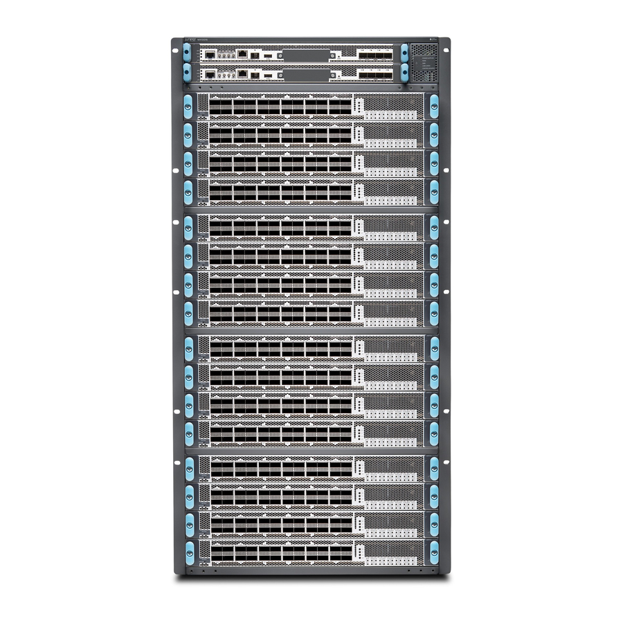
MX10016 Universal Routing Platform Quick Start Guide
IN THIS GUIDE
Quick Start Description
This Quick Start contains information you need to install and configure the MX10016 router. For complete installation
instructions, see the
MX10016 Universal Routing Platform Hardware Guide
WARNING:
warnings for the MX10016 see the MX10016 Hardware Guide. See
Hardware Guide
This guide contains a subset of MX10016 safety information. For the complete list of safety
at https://www.juniper.net/documentation/.
at https://www.juniper.net/documentation/.
MX10016 Universal Routing Platform
Advertisement
Table of Contents

Related Manuals for Juniper MX10016


Summary of Contents for Juniper MX10016
-
Page 1: Table Of Contents
Step 8–Performing Initial Configuration | 29 Safety Warnings Summary | 30 Quick Start Description This Quick Start contains information you need to install and configure the MX10016 router. For complete installation instructions, see the MX10016 Universal Routing Platform Hardware Guide at https://www.juniper.net/documentation/. -
Page 2: Step 1-Preparing The Site For An Mx10016
(SFBs), power supplies, fan trays, and line cards. The router chassis ships in a cardboard box that has a two-layer wooden pallet base. The router chassis is bolted to the pallet base. You can install an MX10016 router in a standard 19 in. - Page 3 Cooling and Airflow Requirements The cooling system in an MX10016 chassis consists of dual fan trays and dual fan tray controllers. There is no air filter in an MX10016. The air intake to cool the chassis is located on the port (line card) side of the chassis. Air flows into the chassis from the ports in the control boards and line cards, through the Switch Fabric Boards (SFBs), and exits from the fan trays and the power supplies.
-
Page 4: Step 2-Unpacking The Mx10016
Leave at least 24 in. (61 cm) both in front of and behind the MX10016 for service personnel to remove and install hardware components. To be NEBS GR-63 compliant, allow at least 30 in. (76.2 cm) in front of the rack and 24 in. (61 cm) behind the rack. - Page 5 A 13/32 in. (10 mm) open-end or socket wrench to remove the bracket bolts from the shipping pallet A box cutter or packing knife to slice open the nylon straps and tape that seal the crate and boxes The chassis ships in a cardboard box that has a two-layer wooden pallet base with foam cushioning between the layers. The router chassis is bolted to the pallet base.
- Page 6 3. Slice the nylon straps with the box cutter that hold the shipping boxes to the pallet. 4. Lift the shipping box off the chassis. 5. Remove the cardboard accessory box. 6. Remove the foam padding from the top of the box. 7.
-
Page 7: Step 3-Mounting The Router Chassis
Installing the Mounting Hardware | 7 Mounting the MX10016 Using a Mechanical Lift | 9 To install the MX10016, first install the mounting hardware and then use a mechanical lift to load the chassis into the rack. Installing the Mounting Hardware Install the mounting hardware on the rack before installing the router. - Page 8 1. Remove the mounting brackets from the accessory box. 2. Decide where to place the chassis in the rack. If the rack is empty, mount the router in the lowest possible location. “Rack-Mounting Requirements” on page 3. Position the left front adjustable mounting bracket at the desired position in the left side of the rack and line up its front screw holes with the holes in the rack.
- Page 9 Hand-tighten the screws fully (to 12–16 in.-lb torque) using a number 2 Phillips screwdriver. Mounting the MX10016 Using a Mechanical Lift Because of the router's size and weight, the MX10016 can safely be installed only by using a mechanical lift. CAUTION: Do not install line cards in the chassis until after you mount the chassis securely on a rack or cabinet.
- Page 10 Figure 6: Loading the MX10016 into a Rack By Using a Mechanical Lift 3. Using the lift, align the router in front of the rack, centering it in front of the mounting brackets. 4. Lift the chassis approximately 0.75 in. (1.9 cm) above the surface of the mounting brackets. Align the chassis as close as possible to the mounting brackets.
-
Page 11: Step 4-Installing Line Cards
Step 4–Installing Line Cards MX10016 line cards are field-replaceable units (FRUs) that can be installed in any of the line card slots on the front of the chassis. The line cards are hot-insertable and hot-removable: You can remove and replace them without powering off the router or disrupting router functions. - Page 12 Phillips (+) screwdriver, number 2 To install a line card in the router chassis: 1. Attach the ESD grounding strap to your bare wrist and connect the strap to the ESD point on the router chassis. The ESD point is located above the status LED panel on the front of the router chassis. See Figure Figure 8: ESD Point on Chassis Front MX 100 16...
- Page 13 Figure 10: Line Card Connectors Connectors — 3. Remove the line card from the electrostatic bag and inspect it for any damage before installing it into the chassis. 4. Grasp and lift the line card by the sides. 5. Slide the line card all the way into the slot until the handle holes align. See Figure Figure 11: Inserting a Line Card into the Slot and Rotating the Handles 6.
-
Page 14: Step 5-Installing The Front Panel
Step 5–Installing the Front Panel The front panel is required on the MX10016 to protect fiber optic cabling and to provide additional protection from electromagnetic interference (EMI). The front panel can be installed with or without the optional cable management system. - Page 15 4. Use the Phillips screwdriver to attach two mounting screws to the latch bracket at the top left of the chassis frame (see Figure 13). Figure 13: Attaching Front Panel Brackets 5. Use the final two mounting screws to attach a latch bracket to the top right of the chassis frame so there are brackets on all four corners of the front of the chassis.
-
Page 16: Step 6-Connecting Power To The Chassis
Figure 14: Front Panel Installation Step 6–Connecting Power to the Chassis IN THIS SECTION Ground the Chassis | 17 Install AC Power Supplies | 19 Install DC Power Supplies | 22 Before supplying power to the MX10016, ensure that you complete these tasks:... - Page 17 A Phillips screwdriver to tighten the two screws that are mounted on the chassis. An AC-powered MX10016 gains additional grounding when you plug the power supply in the router into a grounded AC power outlet by using an AC power cord appropriate for your geographical location.
- Page 18 5. Place the chassis grounding lug and cable over the PEM nuts with the cable connection pointing to the left. See Figure Figure 16: Connecting a Grounding Cable to the MX10016 6. Place the two screws over the grounding lug and grounding cable.
- Page 19 MX10016 power supplies are hot-insertable and are field-replaceable units (FRUs). You can install up to 10 power supplies in an MX10016. The power supplies install in the rear of the chassis in the slots provided along the left side. CAUTION: Do not mix AC and DC power supplies in the same chassis.
- Page 20 Figure 17: Removing the PSU Cover Panel 3. Taking care not to touch power supply connections, remove the power supply from its bag. 4. Peel back and remove the protective plastic wrap that covers all four sides of the power supply. 5.
- Page 21 Figure 18: Installing an AC Power Supply 11. Locate two power cords shipped with the router; the cords have plugs appropriate for your geographical location. 12. Attach each power cord to a dedicated AC power source outlet. 13. Squeeze the two sides of the power cord retainer clip and insert the ends of the clip into the holes in the bracket on each side of the AC appliance inlets on the AC power supply faceplate.
- Page 22 MX10016 power supplies are hot-insertable and are field-replaceable units (FRUs). You can install up to 10 power supplies in an MX10016. The power supplies install in the rear of the chassis in the slots provided along the left side. CAUTION: Do not mix AC and DC power supplies in the same chassis.
- Page 23 “Ground the Chassis” on page 2. Ensure that you have the following parts and tools available to install a DC power supply in an MX10016: Electrostatic discharge (ESD) grounding strap DC power source cables (not provided) with the cable lugs (provided) attached The provided terminal lugs in an MX10016 are sized for 4 AWG (21.1 mm...
- Page 24 5. Remove the plastic cable cover from the DC power input terminals by using the Phillips (+) screwdriver, number 2, to loosen the screws. 6. Remove the nuts from each DC power input terminal, using the 13/32 in. (10 mm) nut driver or socket wrench to loosen the nuts.
- Page 25 Figure 20: Connecting the DC Power Supply Cables to an MX10016 10. Install the plastic cable cover over each set of power cables by using the Phillips (+) screwdriver, number 2, to tighten the screw. 11. If the power supply slot on the chassis has a cover panel on it, insert your thumb and forefinger into the finger holes, then squeeze and pull the cover out of the slot.
- Page 26 Figure 21: Removing the PSU Cover Panel 12. Unscrew the captive screw in the counterclockwise direction by using the Phillips (+) screwdriver, number 1. 13. Pull the captive screw away from the faceplate of the power supply to release the latch. NOTE: You can install the power supplies in any slot labeled PSU 0 through PSU 9 (top to bottom).
- Page 27 Figure 22: Installing an MX10016 DC Power Supply Close latch after power supply is fully installed. Keep latch in open position during installation. Source input 1 enable switch Source input 2 enable switch — — WARNING: Ensure that the power cords do not block access to router components or drape where people can trip on them.
-
Page 28: Step 7-Connecting To The Network
19. Verify that the input 1 and 2 LEDs on the power supply faceplate are lit and are on steadily. 20. Press the power switch to the on (|) position. Step 7–Connecting to the Network You can configure and manage the chassis by using a dedicated console. Every control board has a console port with an RJ-45 connector. -
Page 29: Step 8-Performing Initial Configuration
Step 8–Performing Initial Configuration You must perform the initial configuration of an MX10016 router through the console port using the CLI. Before you begin connecting and configuring the router, set the following parameter values on the console server or PC: Baud Rate—9600... -
Page 30: Safety Warnings Summary
NOTE: When Telnet is enabled, you cannot log in to an MX10016 through Telnet using root credentials. Root login is allowed only for SSH access. 11. Commit the configuration to activate it on the router. - Page 31 A base configuration is about 533 lb (241.77 kg) and redundant configurations can weigh 596 lb (270.34 kg). Installing the MX10016 router in a rack or cabinet requires either a mechanical lift or three people to lift the router and another person to secure it to the rack.
- Page 32 Juniper Networks, the Juniper Networks logo, Juniper, and Junos are registered trademarks of Juniper Networks, Inc. in the United States and other countries. All other trademarks, service marks, registered marks, or registered service marks are the property of their respective owners. Juniper Networks assumes no responsibility for any inaccuracies in this document. Juniper Networks reserves the right to change, modify, transfer, or otherwise revise this publication without notice.