Kyocera TASKalfa 3510i Service Manual
Hide thumbs
Also See for TASKalfa 3510i:
- Operation manual (532 pages) ,
- Technical reference manual (260 pages) ,
- User manual (115 pages)

Related Manuals for Kyocera TASKalfa 3510i


Summary of Contents for Kyocera TASKalfa 3510i
-
Page 1: Service Manual
TASKalfa 3010i TASKalfa 3510i SERVICE MANUAL Published in September 2016 842NL11B 2NLSM06B Rev.B... - Page 2 Notation of products in the manual For the purpose of this service manual, products are identified by print speed at A4 and black and white modes. TASKalfa 3010i : 30 ppm model TASKalfa 3510i : 35 ppm model...
-
Page 3: Revision History
Revision history Revision Date Pages Revised contents 21 August 2013 1-2-11 The addition about a default position of the manual-sta- ple. 1-3-28 Added the item : PH / PH Boot 1-3-90, 91 Added the operating sequences 1-3-92 Added the item : Tray HP2 Deleted the item : Tray L-Limit(BL) 1-3-98, 99 Correction : Change in value per step of U246... - Page 4 Revision Date Pages Revised contents 25 July 2014 1-1-2 Correction: Interface (Option) 1-4-21 to 25 Deleted: Connector number of PF main PWB 1-4-28 1-4-26 Correction: Code No.2200 → 2000 5 September 2014 Caontents Change: Page numbers of the contents 1-5-27 to 37 Added: (4)Detaching and refitting the scanner wires 19 September 1-1-1 to 3...
-
Page 5: Safety Precautions
Safety precautions This booklet provides safety warnings and precautions for our service personnel to ensure the safety of their customers, their machines as well as themselves during maintenance activities. Service personnel are advised to read this booklet carefully to familiarize themselves with the warnings and precautions described here before engaging in maintenance activities. - Page 6 Safety warnings and precautions Various symbols are used to protect our service personnel and customers from physical danger and to prevent damage to their property. These symbols are described below: DANGER: High risk of serious bodily injury or death may result from insufficient attention to or incorrect compliance with warning messages using this symbol.
-
Page 7: Installation Precautions
1. Installation Precautions WARNING • Do not use a power supply with a voltage other than that specified. Avoid multiple connections to one outlet: they may cause fire or electric shock. When using an extension cable, always check that it is adequate for the rated current...................... •... - Page 8 2. Precautions for Maintenance WARNING • Always remove the power plug from the wall outlet before starting machine disassembly....• Always follow the procedures for maintenance described in the service manual and other related brochures............................• Under no circumstances attempt to bypass or disable safety features including safety mechanisms and protective circuits.
- Page 9 • Do not remove the ozone filter, if any, from the copier except for routine replacement....... • Do not pull on the AC power cord or connector wires on high-voltage components when removing them; always hold the plug itself......................•...
- Page 10 This page is intentionally left blank.
- Page 11 2NL/2P8-2 CONTENTS 1-1 Specifications 1-1-1 Specifications ........................1-1-1 1-1-2 Parts names .......................... 1-1-6 (1) Machine (front side)......................1-1-6 (2) Machine (rear side)......................1-1-8 (3) Operation panel ........................ 1-1-9 1-1-3 Machine cross section ......................1-1-10 1-2 Installation 1-2-1 Installation environment......................1-2-1 1-2-2 Unpacking and installation.....................
-
Page 12: Nl/2P8
(1) Precautions........................1-5-1 (2) Drum unit .......................... 1-5-1 (3) Toner ..........................1-5-1 (4) How to tell a genuine Kyocera toner container..............1-5-2 1-5-2 Outer covers .......................... 1-5-3 (1) Detaching and refitting the front cover................1-5-3 (2) Detaching and refitting the rear cover ................1-5-5 (3) Detaching and refitting the inner tray................ - Page 13 2NL/2P8-9 1-5-7 Fuser section ........................1-5-18 (1) Detaching and refitting the fuser unit................1-5-18 1-5-8 Drive section ........................1-5-19 (1) Detaching and refitting the drive unit 1 ................1-5-19 (2) Detaching and refitting the drive unit 2 ................1-5-20 1-5-9 Optical section ........................1-5-21 (1) Detaching and refitting the laser scanner unit ..............
- Page 14 2NL/2P8-9 2-3 Operation of the PWBs 2-3-1 Main PWB..........................2-3-1 2-3-2 Engine PWB ........................2-3-10 2-3-3 ISC PWB ..........................2-3-22 2-3-4 Operation panel PWB main ....................2-3-27 2-3-5 Power source PWB ......................2-3-32 2-4 Appendixes 2-4-1 Appendixes ..........................2-4-1 (1) List of maintenance parts ....................2-4-1 (2) Maintenance kits.......................
- Page 15 2NL/2P8-A 1-1 Specifications 1-1-1 Specifications Machine Specifications Item 30ppm 35ppm Desktop Type Electrophotography by semiconductor laser Printing method Sheet, Book, 3-dimensional objects (maximum original size: A3/Ledger) Originals Fixed Original feed system 60 to 163 g/m Cassette Paper weight 45 to 256 g/m , (Sizes is larger than A4/Letter: 52 to 163 g/m MP tray Plain, Preprinted, Bond, Recycled, Vellum, Rough, Letter Head, Color, Pre-...
- Page 16 2NL/2P8-A Specifications Item 30ppm 35ppm When the DP is not used : 3.6 s or less First copy time When using the DP : 5.6 s or less (A4, feed from cassette) Power on : 23 s or less Low power mode : 10 s or less Warm-up time Sleep mode...
- Page 17 2NL/2P8-A Specifications Item 30ppm 35ppm Temperature 10 to 32.5 °C/50 to 90.5 °F 15 to 80% RH Humidity Operating environment 2,500 m/8,202 ft or less Altitude 1,500 lux or less Brightness 594 × 738 × 683 mm / 23 3/8” × 29 1/16 “× 26 7/8” Dimensions (W ×...
- Page 18 2NL/2P8-3 Printer Specifications Item 30ppm 35ppm Cassette MP tray Cassette MP tray A4/Letter 30 sheets/min 21 sheets/min 35 sheets/min 24 sheets/min A4R/LetterR 22 sheets/min 17 sheets/min 26 sheets/min 20 sheets/min A3/Ledger 15 sheets/min 14 sheets/min 17 sheets/min 16 sheets/min Printing B4/Legal 15 sheets/min 14 sheets/min...
- Page 19 2NL/2P8-2 Scanner Item Specifications 600 dpi, 400 dpi, 300 dpi, 200 dpi, 200 × 100dpi, 200 × 400dpi Resolution JPEG, TIFF, PDF, XPS File format B/W : 80 images/min Color: 50 images/min Simplex (A4 landscape,300 dpi, Image quality: Text/Photo original) Scanning speed * B/W : 160 images/min...
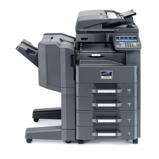
- Page 20 2NL/2P8 1-1-2 Parts names (1) Machine (front side) Figure 1-1-1 1. Cassette 6. MP Paper width guides 2. Paper width guides 7. Inner tray 3. Paper length guide 8. Operation panel 4. MP (multi purpose) tray 9. USB memory slot 5.
- Page 21 2NL/2P8 Figure 1-1-2 11. Waste toner box 18. Fuser unit 12. Waste toner box (Reserve) 19. Toner container 13. Front cover 20. Drum unit 14. Right cover 1 21. Developing unit 15. Right cover 2 22. Toner container lever 16. Transfer roller 23.
- Page 22 2NL/2P8 (2) Machine (rear side) 34 35 Figure 1-1-3 25. DP connect connector cover 32. Option interface slot 2 26. DP interface connector 33. Option interface slot 1 27. FAX memory cover 34. Network interface connector 28. Scanner lock cover 35.
- Page 23 2NL/2P8 (3) Operation panel 13 14 16 17 21 22 23 24 Figure 1-1-4 1. Status/Job cancel key 10. Main power indicator 19. Attention indicator 2. System menu key 11. Help key 20. Enter key 3. Counter key 12. Accessibility display key 21.
- Page 24 2NL/2P8 1-1-3 Machine cross section Light path Paper path Paper path (option) Figure 1-1-5 1. Cassette 1 5. MP tray paper feed section 11. Toner container 2. Cassette 1 paper feed sec- 6. Conveying section 12. Fuser unit tion 7. Transfer/Separation section 13.
- Page 25 2NL/2P8 1-2 Installation 1-2-1 Installation environment 1. Temperature: 10 to 32.5°C/50 to 90.5°F 2. Humidity: 15 to 80% RH 3. Power supply: 120 V AC, 12.0 A 220 - 240 V AC, 6.5 A 4. Power supply frequency: 50 Hz ±2%/60 Hz ±2% 5.
-
Page 26: Unpacking And Installation 1
2NL/2P8 1-2-2 Unpacking and installation (1) Installation procedure Start Connect the power cord Unpack Execution of initial-setting operation Remove the tapes and spacer Execution of mentenance item U952 Install the optional paper feeder Set cassette heater control Load paper (maintenance item U327) Install the toner container Setting the delivery date (maintenance item U278) - Page 27 2NL/2P8 Unpacking Figure 1-2-2 1. Skid 9. Accessory box 17. Pad LF 2. Hinge joints 10. Pad F 18. Installation guide, etc. 3. Bottom pad RF 11. Pad R 19. Poly bag 4. Bottom pad RR 12. Stay 20. DP wire cover 5.
- Page 28 2NL/2P8 Remove the tapes and spacer Tape Protection pad 1. Remove two tapes and the protection pad. 2. Remove two tapes and the paper. 3. Remove two tapes from the main unit. Tape Tape Paper Tape Tape Tape Figure 1-2-3 4.
- Page 29 2NL/2P8 Install the optional paper feeder (option) 1. Install the optional paper feeder as required. Note: Refer to the installation manual of a paper feeder for details. Main unit Paper feeder Figure 1-2-5 Load paper Paper 1. Take out the paper preservation bag. preservation bag 2.
- Page 30 2NL/2P8 3. Adjust the paper length guide to fit the paper size. Paper length guide Figure 1-2-7 4. Align the paper so that it is abut with the Paper Cassette right end of the cassette. 5. Insert the cassette size plate. 6.
- Page 31 2NL/2P8 Install the toner container 1. Open the front cover. 2. Hold the toner container vertically and tap the upper part five times or more. Turn the toner container upside down and tap the upper part five times or more. Toner container Figure 1-2-9 3.
- Page 32 2NL/2P8 4. Shake the toner container approxi- mately five or six times in the horizontal direction to stir toner. Toner container Figure 1-2-11 5. Gently push the toner container into the CLICK! machine. Push the container all the way into the machine until it locks in place.
- Page 33 2NL/2P8-A Switch the cassette heater switch 1. Release the hook and then remove the switch cover. 2. Turn the cassette heater switch on. Note: When the cassette heater is used, it turns it on. 3. Refit the switch cover. Cassette heater Switch cover switch Figure 1-2-13...
- Page 34 2NL/2P8 Attaching the language label (Excluding 240V AC model) 1. Insert a flat-head screwdriver and slide the operation panel covers A and B to remove them. Operation panel cover B Operation panel cover A Figure 1-2-14 Clear panel 2. Remove the clear panel. Figure 1-2-15 Operation panel sheet 3.
- Page 35 2NL/2P8-1 Install the other optional devices Install the optional devices (Document finisher, Fax kit, etc.) as required. Changing the default staple position of Manual Stapling If the inch size paper is used, use the procedure below to change the default Staple Position after turning the main power switch on.
- Page 36 2NL/2P8 Connect the power cord 1. Connect the power cord to the connector on the machine. 2. Insert the power plug into the wall outlet. Wall outlet Power code Figure 1-2-18 Installing toner 1. Turn the main power switch on. The machine automatically starts to feed toner in the developer unit.
- Page 37 2NL/2P8 [Set cassette heater control (maintenance item U327)] 1. Enter the maintenance mode by entering 10871087 using the numeric keys. 2. Enter 327 using the numeric keys and press the start key. 3. Select [On]. 4. Press the start key. The setting is set. 5.
- Page 38 2NL/2P8 (2) Setting initial copy modes Factory settings are as follows: Maintenance Contents Factory setting item No. 600000 U250 Checking/clearing the maintenance cycle 300000 300000 300000 300000 U251 Checking/clearing the maintenance counter 0/0/0/0/0/0 U252 Setting the destination U253 Switching between double and single counts Double count (A3/Ledger) U260...
- Page 39 2NL/2P8 1-2-3 Option composition DP-770(B) DP-772 DP-773 MT-730 PLATEN COVER TYPE E DF-791 DF-770(D) AK-740 PH-7B PF-810 PF-791 1-2-15...
-
Page 40: Table Of Contents
2NL/2P8 Copy guard kit (B) Card Authentication kit (B) MM-16-128 Fax System(W) Key counter Software option Internet FAX Kit (A) Data Security kit (E) UG-33 IB-50 MK-2 UG-34 Scan extension kit (A) IB-51 DT-730 1-2-16... - Page 41 2NL/2P8 1-2-4 Installing the key counter (option) (1) Installing directly on the device Key counter installation requires the following parts: Parts Quantity Part.No. 3025418011 Key counter 302A369709 Key counter set 302NL46320 Key counter wire Wire saddle B 7YZM610008++H01 Wire saddle C 7YZM610009++H01 Supplied parts of key counter set (302A369709): Parts...
- Page 42 2NL/2P8 Parts Quantity Part.No. B1B03080 M3 x 8 bronze binding screw B1B54300 M4 x 30 tap-tight S screw B4A04060 M4 x 6 chrome TP screw B4A04100 M4 x 10 chrome TP screw * : Not used in this model. ▲: One piece is used in this model. Procedure 1.
- Page 43 2NL/2P8 5. Remove seven screws. 6. Pull the rear cover upwards and then Rear cover release three hooks. 7. Remove the rear cover. Screw Screw Screw Screw Screw Screw Hooks Hook Screw Figure 1-2-20 Screw 8. Remove two screws and then remove Scanner right cover the scanner right cover.
- Page 44 2NL/2P8 Ribs 10. Cut out the aperture plate (right side) on the right upper cover using nippers. Right upper cover Aperture plate Figure 1-2-22 Screw 11. Remove two screws and then remove the scanner rear cover. Scanner rear cover Screw Figure 1-2-23 1-2-20...
- Page 45 2NL/2P8 12. Attaches the wire saddle B and the wire saddle C to right upper section of the machine and then release two hooks of the thir. 13. Attach the edging to the aperture part. Wire saddle C Edging Wire saddle B Figure 1-2-24 Wire saddle C 14.
- Page 46 2NL/2P8 15. Pass the key counter wires through the edging. 16. Pass the key counter wires through the wire saddle and then connect the connector of the key counter wires to the connector of the engine PWB. Edgeing 17. Fit the scanner rear cover using two screws.
- Page 47 2NL/2P8 Key counter electrical wires 22. Connect the key counter signal cable to the key counter electrical wires. 23. Fit the key counter cover to the M4 x 6 screw machine using the M4 x 6 screw. 24. Fit the rear cover using seven screws. 25.
- Page 48 2NL/2P8 (2) Mounting on the document table Key counter installation requires the following parts Parts Quantity Part.No. 3025418011 Key counter 302A369709 Key counter set 302MV46090 Key counter wire 1902LC0UN2(option) Document table Wire saddle A 7YZM610010++H01 Wire saddle B 7YZM610008++H01 Wire saddle C 7YZM610009++H01 Supplied parts of key counter set (302A369709): Parts...
- Page 49 2NL/2P8 Parts Quantity Part.No. B4A04100 M4 x 10 chrome TP screw Supplied parts of document table (1902LC0UN2) Parts Quantity Part.No. Tray stay Tray mount 302LC04601 Tray cover 302LC04710 Tray lower cover Tray retainer 2▲ 302LC04660 Sheet 303NS24410 3CY06030 M4 nut 7▼...
- Page 50 2NL/2P8 5. Remove seven screws. 6. Pull the rear cover upwards and then Rear cover release three hooks. 7. Remove the rear cover. Screw Screw Screw Screw Screw Screw Hooks Hook Screw Figure 1-2-30 Screw 8. Remove two screws and then remove Scanner right cover the ISU right cover.
- Page 51 2NL/2P8 10. Cut out four ribs of the aperture plate Ribs (left side) on the right upper cover using nippers. Note: Cut off the rib (lower part) Aperture certainly so that a projection does not remain. Rib (lower part) Right upper cover Figure 1-2-32 Screw 11.
- Page 52 2NL/2P8 12. Attaches the wire saddle B and the wire saddle C to right upper section of the machine and then release two hooks of the thir. 13. Attach the edging to the aperture part. Wire saddle C Edging Wire saddle B Figure 1-2-34 Wire saddle C 14.
- Page 53 2NL/2P8 16. Pass the key counter wires through the edging. 17. Pass the key counter wires through the wire saddle and then connect the connector of the key counter wires to the connector of the engine PWB. Edgeing 18. Fit the scanner rear cover using two screws.
- Page 54 2NL/2P8 22. Snap in the tray mount to the tray stay and fix using two screws. Tray mount Figure 1-2-38 1-2-30...
- Page 55 2NL/2P8 23. Cut out the aperture plate on the tray Tray cover cover using nippers. 24. Fit the tray cover to the tray stay using Aperture four screws. M4 x 8 screws M4 x 8 screws Tray cover Figure 1-2-39 25.
- Page 56 2NL/2P8 26. Pass the key counter signal cable through the aperture in the document table. Key counter M4 x 6 screw cover 27. Fit the key counter cover to the docu- ment table using the screw. 28. Connect the key counter signal cable to the key counter wire.
- Page 57 2NL/2P8 29. Fit the tray lower cover. Note: Install the key counter signal cable and key counter wire so that they are held behind the tray lower cover. Tray lower cover Connector Figure 1-2-42 1-2-33...
- Page 58 2NL/2P8 30. Secure the tray lower cover with two pins. Tray lower cover Figure 1-2-43 Sheet 31. Adhere the sheet onto right side of the document table. 32. Fit the rear cover using seven screws. 33. Insert the key counter into the key counter socket assembly.
- Page 59 2NL/2P8 1-2-5 Installing the gigabit ethernet board (option) Gigabit ethernet board installation requires the following parts: Parts Quantity Part.No. Gigabit ethernet board 1505JV0UN0 (option) Procedure 1. Press the power key on the operation panel to off. Make sure that the power indicator and the memory indicator are off before turning off the main power switch.
- Page 60 2NL/2P8 3. Insert the gigabit ethernet board along the groove in OPT2 and secure the board with two pins that have been removed in step 2. Gigabit ethernet Caution: Do not directly touch the giga- board bit ethernet board terminal. Hold the top and bottom of the gigabit ethernet board, or the projection of the board to insert the gigabit ethernet...
- Page 61 2NL/2P8 1-2-6 Installing the IC card reader holder (option) IC card reader holder installation requires the following parts: Parts Quantity Part.No. IC card reader holder (E) 1709AD0UN1 (option) Supplied parts of IC card reader holder (E) (1709AM0UN1): Parts Quantity Part.No. IC card reader holder Label Bundling band...
- Page 62 2NL/2P8 4. Release the lock part and remove the upper cover B. Lock part Upper cover B Figure 1-2-49 IC card reader 5. The mounting procedure differs depending type of IC card readers. Type A: Thicker and in the same size as its holder Type A Continue to step 6.
- Page 63 2NL/2P8 6. Affix two hook and loop fasteners to the IC card reader holder IC card reader and IC card reader holder. Hook and loop fasteners Hook and loop fasteners IC card reader (Type A) 7. Mount the IC card reader to the IC card IC card reader holder reader holder.
- Page 64 2NL/2P8 8. Affix two hook and loop fasteners to the IC card reader holder IC card reader and IC card reader holder. Hook and *: Affix a hook and loop fastener onto the IC loop fasteners card reader so that it is mounted on the holder with both being flush with the right side edges.
- Page 65 2NL/2P8 10. Route the USB cable from the IC card IC card reader holder reader through the IC card reader holder ribs, wind four timesaround its back and route through another rib. Proceed to step 15. USB cable Ribs Figure 1-2-53 1-2-41...
- Page 66 2NL/2P8 11. Affix two hook and loop fasteners to the IC card reader holder IC card reader. 12. Affix a hook and loop fastener at the reverse side of the spacer where an Spacer adhesive tape has been affixed. Affix two spacers to the IC card reader. Hook and loop fasteners Spacer...
- Page 67 2NL/2P8 14. Route the USB cable from the IC card USB cable reader through the ribs at the bottom of IC card reader holder the IC card reader holder, wind around its back, and route through the rib on the left hand side. *: Make sure the cable will have a slack of about 15 cm.
- Page 68 2NL/2P8 15. Hook the IC card reader holder onto the machine by mating the two holes on the holder with the hooks on the machine. IC card reader holder fixing part Hooks IC card reder holder Figure 1-2-56 16. For only type A or B of the IC card reader, bundle the surplus length of the cable and insert it into the wire holder.
- Page 69 2NL/2P8 17. Connect the USB cable with the USB connector on the machine. USB connector If a keyboard holder is planned to be added, connect it to the connector on the USB wire far end. Figure 1-2-58 Positioning mark 18. Affix a label on the upper cover B align- ing it with the positioning mark.
- Page 70 2NL/2P8 19. Fit the upper cover B by sliding and uniting two projections and two holes. Projections Holes Upper cover B Figure 1-2-60 20. Replace the staple cover and the staple holder in their original positions. Staple cover Screw Staple holder Figure 1-2-61 1-2-46...
- Page 71 2NL/2P8 Enabling IC Card Authentication Precautions To install the optional function, you need the License Key. Please access the designated website of your dealer or service representative, and register “Machine No.” indicated on your machine and “Product ID” indi- cated on the License Certificate supplied with the product to issue the License Key. 1.
- Page 72 2NL/2P8 1-2-7 Installing the keyboard holder (B) (option) Keyboard holder (B) installation requires the following parts: Parts Quantity Part.No. Keyboard holder (B) 1709AF0UN1 (option) Supplied parts of keyboard holder (B) (1709AF0UN1): Parts Quantity Part.No. Upper keyboard holder Lower keyboard holder Upper keyboard cover Lower keyboard cover Cable cover...
- Page 73 2NL/2P8 4. Remove a screw. Screw Figure 1-2-63 5. Fit the lower keyboard mounting bracket with the machine using the two S Tite screws M4 x 14 Lower keyboard mounting bracket S Tite screws M4 x 14 Figure 1-2-64 1-2-49...
- Page 74 2NL/2P8 6. Latch the hook of the lower lid with the S Tite screws machine. M3 x 8 7. Fit the lower lid with the machine using a S Tite screws M3 x 8. Lower lid Hook Lower lid Figure 1-2-65 S Tite screw S Tite screws 8.
- Page 75 2NL/2P8 9. Cut out the cutaway portion of the lower Cutaway portion keyboard cover by using a pair of nip- pers. Lower keyboard cover Figure 1-2-67 10. Insert the two positioning pins at the hooks bottom of the lower keyboard cover in Upper keyboard hole the holes on the keyboard mounting...
- Page 76 2NL/2P8 12. Fix the lower keyboard mounting P Tite screws bracket onto the upper keyboard M3 x 8 mounting bracket using the two P Tite screws M3 x 8. Lower keyboard cover Figure 1-2-69 13. Fix the lower keyboard mounting S Tite screws bracket onto the upper keyboard M3 x 8...
- Page 77 2NL/2P8 Hook and loop fasteners 14. Affix two pieces of hook and loop fas- teners on the upper keyboard cover. Figure 1-2-71 15. Fix the keyboard with the hook and loop fasteners. USB connector 16. Connect the USB cable with the USB connector on the machine.
- Page 78 2NL/2P8 17. Bundle the surplus length of the cable Bunding bands with two bundling bands and hook it on the hook of the upper keyboard cover. Hook Figure 1-2-73 18. Slide the upper lid and fix in the machine. Upper lid Figure 1-2-74 1-2-54...
- Page 79 2NL/2P8 19. Fix the cable cover on the machine. Latch the three hooks at the near end Cable cover and press the hooks downwards to mate with the holes at the far end. Hole Holes Cable cover Hook Hook Hook Figure 1-2-75 20.
- Page 80 2NL/2P8 1-2-8 Installing the Printed Document Guard Kit (option) Printed Document Guard Kit installation requires the following parts: Parts Quantity Part.No. Printed Document Guard Kit (B) 1503P40UN0 Supplied parts of Printed Document Guard Kit : Parts Quantity Part.No. Copy guard PWB FFC (short) FFC (long) Mount plate B...
- Page 81 2NL/2P8 [When DP junction PWB is not used] 6. Remove four screws and then refit it after rotating the mount plate 180 FFC (long) degrees. 7. Insert the FFC into the copy guard PWB Screw until it clicks in. Copy guard PWB WIthout a DP junction PWB: Screw A FFC is used at YC2...
- Page 82 2NL/2P8 9. Remove two screws and remove the DP PWB cover. 10. Pass the FFC through the aperture Screw section of the controller box. Screw Controller box DP PWB cover aperture part Figure 1-2-80 11. Connect the main-circuit PWB with the FFC.
- Page 83 2NL/2P8 [When DP junction PWB is used] 13. Remove four screws and then refit it after rotating the mount plate 180 FFC(short) FFC(long) degrees. 14. Insert the FFC into the copy guard PWB until it clicks in. Screw Copy guard PWB WIth a DP junction PWB: The FFCs is used at YC2 (serigraphed Screw...
- Page 84 2NL/2P8 16. Remove two screws and remove the DP PWB cover. 17. Pass the FFC through the aperture Screw section of the controller box. Screw Controller box DP PWB cover aperture part Figure 1-2-84 18. Connect the main-circuit PWB with the FFC.
- Page 85 2NL/2P8 19. Fit the DP junction PWB using two screws. DP junction PWB Screw Screw Figure 1-2-86 20. Connect the main PWB and the DP junction PWB with the FFC. DP junction PWB (YC35) 21. Refit the DP PWB cover and the rear cover.
- Page 86 2NL/2P8 1-2-9 Installing the key card MK-2 (option for Japan only) Key card installation requires the following parts: Parts Quantity Part.No. Key card MK-2 8J272002(option) MK-2 mount Supplied with MK-2 M4 x 16 screw 1902LC0UN2(option) Document table Bushing M1203490 Mount 78660130 M3×8 tap-tight p screw TP 7BB202308H...
- Page 87 2NL/2P8 Procedure Aperture part 1. Remove seven screws. 2. Pull the rear cover upwards and then Rear cover release three hooks. 3. Remove the rear cover. 4. Cut the aperture part (left side) of the Screw rear cover using nippers etc. Screw Screw Screws...
- Page 88 2NL/2P8 7. Remove fifteen screws and remove the controller box cover. Screw Screw Screws Screws Screw Screw Controller box cover Screw Screw Figure 1-2-90 8. Remove five connectors, three USB Connectors and FFC from the main PWB. 9. Remove six wire holders and release the wires and FFC.
- Page 89 2NL/2P8 10. Remove six screws. 11. Pull the left lower cover upwards and release four hooks. Screw 12. Remove the left lower cover. Screw Screw Screw Screw Screw Left lower cover Hooks Figure 1-2-92 13. Remove six screws and then remove the controller box.
- Page 90 2NL/2P8 14. Pass the key card wires through the Key card wires bandage lid, bushing and the aperture parts of the rear cover. 15. Connect the connector of the key card wires to the engine PWB. Bandage lid Connector Bushing Key card wires Engine PWB Figure 1-2-94...
- Page 91 2NL/2P8 Key card wires 18. Push the rear cover downwards and then hook three hooks. Rear cover 19. Fit the rear cover using seven screws. Screws * : Pull out the slack electric wires inside a Bandage machine. Screw Bushing 20.
- Page 92 2NL/2P8 22. Snap in the tray mount to the tray stay and fix using two M4 x 8 screws. Tray mount ? 1?2?98 1-2-68...
- Page 93 2NL/2P8 M4×8 screws 23. Fit the tray cover to the tray stay using four M4 x 8 screws. M4×8 screws Tray cover Try stay Figure 1-2-99 24. Remove the four screws securing the MK-2 cover; attach the MK-2 mount to the MK-2, and secure using the four screws.
- Page 94 2NL/2P8 M4×20 tap-tight 25. Fit the MK-2 to the document table M4×20 tap-tight S screw S screw using two M4 x 20 tap-tight S screws. *: Secure the screws to the location with mark “B”. MK-2 Document table Figure 1-2-101 1-2-70...
- Page 95 2NL/2P8 26. Fit the tray lower cover. 27. Secure the tray lower cover with two pins. Tray lower cover Figure 1-2-102 1-2-71...
- Page 96 2NL/2P8 Sheet 28. Adhere the sheet onto right side of the document table. 29. Turn the main power switch on and enter the maintenance mode. 30. Run maintenance item U204 and select Document [Key-Card] (see page 1-3-80). table 31. Exit the maintenance mode. Figure 1-2-103 1-2-72...
- Page 97 2NL/2P8 1-2-10 Installing the coin vender (option for japan only) Coin vender installation requires the following parts: Parts Quantity Part.No. Coin vender ACV-1 (option) Vender wire Vender base Supplied with coin vender M4 x 6 screw M4×8 ground screw Procedure 1.
- Page 98 2NL/2P8 5. Remove two screws and then remove the lid. Screw Screw ? 1?2?105 6. Pass the vender wire through the aper- Vender wire connector ture in the IF mount. IF mount aperture 7. Secure the vender wire with two screws removed in step 5.
- Page 99 2NL/2P8 10. Fit the rear cover using seven screws. 11. Connect the signal cable of coin vender to connector of the vender wire. Vender wire connector 12. Turn the main power switch on and enter the maintenance mode. 13. Run maintenance mode U206 and acti- vate 'Coin vender is installed.’...
- Page 100 2NL/2P8 This page is intentionally left blank. 1-2-76...
- Page 101 2NL/2P8 1-3 Maintenance Mode 1-3-1 Maintenance mode The machine is equipped with a maintenance function which can be used to maintain and service the machine. (1) Executing a maintenance item Start Press the status/Job cancel key. Enter “10871087” using Maintenance mode is entered. the numeric keys.
- Page 102 2NL/2P8-A (2) Maintenance modes item list Item Initial Section Content of maintenance item setting General U000 Outputting an own-status report U001 Exiting the maintenance mode U002 Setting the factory default data U003 Setting the service telephone number U004 Setting the machine number U010 Setting the maintenance mode ID U018 Check Firmware Checksum U019 Displaying the firrmware version...
- Page 103 2NL/2P8-3 Item Initial Section Content of maintenance item setting Optical U061 Checking the operation of the exposure lamp U063 Adjusting the shading position U065 Adjusting the scanner magnification U066 Adjusting the scanner leading edge registration U067 Adjusting the scanner center line U068 Adjusting the scanning position for originals from the DP -/-/-/-...
- Page 104 2NL/2P8-A Item Initial Section Content of maintenance item setting High volt- U108 Setting separation shift bias U110 Checking the drum count U111 Checking the drum drive time U117 Checking the drum number U118 Displaying the drum history U127 Checking/clearing the transfer count Developer U130 Initial setting for the developer U139 Displaying the temperature and humidity outside...
- Page 105 2NL/2P8 Item Initial Section Content of maintenance item setting Operation U206 Setting the presence or absence of a coin vender panel and On/Off Config support No Coin Action equipment Normal 10/10/10/10 100/50/30/50 100/50/30/50 Full Color 100/50/30/50 10/10/10/10 100/50/30/50 100/50/30/50 Full Color 100/50/30/50 Print 10/10/10/10...
-
Page 106: U250 Checking/Clearing The Maintenance Cycle
2NL/2P8-A Item Initial Section Content of maintenance item setting 600000/0/300000/300000/300000/ Mode set- U250 Checking/clearing the maintenance cycle ting 300000 0/0/0/0/0/0 U251 Checking/clearing the maintenance counter Inch/Europe Metric U252 Setting the destination Double count U253 Switching between double and single counts (A3/Ledger) Eject U260 Selecting the timing for copy counting... - Page 107 2NL/2P8 Item Initial Section Content of maintenance item setting Image U425 Setting the target processing Chart1 White 93.6/0.9/-0.4 Black 10.6/-0.2/-0.7 Grav1 76.2/-0.2/1.2 Grav2 25.2/-0.2/-0.2 Grav3 51.3/-0.3/0.3 72.6/-32.8/-11.5 48.1/69.9/-6.1 86.2/-18.6/81.7 46.7/54.2/38.6 67.8/-51.3/48.9 38.8/25.3/-22.8 Adjust Original 5.0/10.0/190.0 Chart2/CCD N875 85.4/0.0/1.1 N475 52.0/-1.3/2.4 N125 21.0/-0.5/2.5 55.2/-29.7/-45.0...
- Page 108 2NL/2P8 Item Initial Section Content of maintenance item setting U600 Initializing all data U601 Initializing permanent data U603 Setting user data 1 U604 Setting user data 2 U605 Clearing data U610 Setting system 1 Setting:[Cut Line(100%)] Setting:[Cut Line(Auto)] Setting:[Cut Line(100%)] U611 Setting system 2 Setting:[Adj Lines] Setting:[Adj Lines(A4)]...
- Page 109 2NL/2P8 Item Initial Section Content of maintenance item setting U633 Setting communication control 4 Setting:[V.34] Setting:[DIS 2Res] Setting:[DIS 2Res] Once Setting:[RTN Check] U634 Setting communication control 5 U640 Setting communication time 1 Setting:[Time (One)] Setting:[Time (Cont)] U641 Setting communication time 2 Setting:[T0 Time Out] Setting:[T1 Time Out] Setting:[T2 Time Out]...
- Page 110 2NL/2P8 Item Initial Section Content of maintenance item setting 0/0/0/0/0/0 Others U901 Checking copy counts by paper feed locations U903 Checking/clearing the paper jam counts U904 Checking/clearing the call for service counts U905 Checking counts by optional devices U906 Resetting partial operation control U908 Checking the total counter value U910 Clearing the print coverage data 0/0/0/0/0/0...
- Page 111 2NL/2P8 (3) Contents of the maintenance mode items Item No. Description U000 Outputting an own-status report Description Outputs lists of the current settings of the maintenance items and paper jam and service call occurrences. Outputs the event log. Also sends output data to the USB memory. Purpose To check the current setting of the maintenance items, or paper jam or service call occurrences.
- Page 112 2NL/2P8 Item No. Description U000 Method: Send to the USB memory 1. Press the power key on the operation panel, and after verifying the main power indicator has gone off, switch off the main power switch. 2. Insert USB memory in USB memory slot. 3.
-
Page 113: Event Log
2NL/2P8 Item No. Description U000 Event log Event Log 2013/02/18 15:15 TASKalfa 3510i Firmware version 2NL_2000.000.000 2013.02.18 [XXXXXXXX] [XXXXXXX] [XXXXXXX] [XXXXXXXX] (12) Paper Jam Log Counter Log Count. Event Descriprions J0100: J4201: C0030: T00: 1876543 0501.01.08.01.01 J0101: J4202: C0070: T01: 166554 4002.01.08.01.01... - Page 114 2NL/2P8 Item No. Description U000 Detail of event log Items Description System version System date Engine soft version Engine boot version Controller BROM version Operation panel mask version Machine serial number Paper Jam Count. Event Remembers 1 to 16 of The total page count Log code (hexadeci- occurrence.
- Page 115 2NL/2P8 Item No. Description U000 Items Description Paper Jam (d) Detail of paper type (Hexadecimal) cont. 01: Plain 0A: Color 15: Custom 1 02: Transparency 0B: Prepunched 16: Custom 2 03: Preprinted 0C: Envelope 17: Custom 3 04: Labels 0D: Cardstock 18: Custom 4 05: Bond 0E: Coated...
- Page 116 2NL/2P8 Item No. Description U000 Items Description (11) Unknown Toner Count. Item Remembers 1 to 5 The total page count Unknown toner log of occurrence of at the time of the code unknown toner toner empty error (1 byte, 2 categories) detection.
-
Page 117: Service Status Page
2NL/2P8 Item No. Description U000 Service status page (1) Service Status Page 2013/02/18 15:15 Firmware version 2NL_2000.000.000 2013.02.18 [XXXXXXXX] [XXXXXXXX] [XXXXXXXX] Controller Information (30) FAX Information Slot1/Slot2 (31) Rings (Normal) Memory status (32) Rings (FAX/TEL) Total Size 2.0 GB (33) Rings (TAD) (34) Option DIMM Size... - Page 118 2NL/2P8 Item No. Description U000 Service status page (2) Service Status Page 18/02/2013 15:15 Firmware version 2NL_2000.000.000 2013.02.18 [XXXXXXXX] [XXXXXXXX] [XXXXXXXX] Engine Information Send Information (40) NVRAM Version _1F31225_1F31225 (44) Date and Time 2013/02/18 15:30 (41) Scanner Version 2LC_1200.001.089 (45) Address mail@bjd.ne.jp (42)
- Page 119 2NL/2P8 Item No. Description U000 Detail of service status page Description Supplement Firmware version System date Engine soft version Engine boot version Operation panel mask version Machine serial number Total memory size Local time zone Report output date Day/Month/Year hour:minute (10) NTP server name (11)
- Page 120 2NL/2P8 Item No. Description U000 Description Supplement (25) Average coverage for copy Black (26) Average coverage for printer Black (27) Average coverage for fax Black (28) Cleared date and output date (29) Coverage on the final output page (30) Fax kit information This item is printed only when the fax kit is installed.
- Page 121 2NL/2P8 Item No. Description U000 Description Supplement (41) Scanner firmware version (42) Fax firmware version This item is printed only when the fax kit is installed. (43) Mac address (44) The last sent date and time (45) Transmission address (46) Destination information (47) Area information...
- Page 122 2NL/2P8-4 Item No. Description U000 Description Supplement (62) Media type attributes Weight settings Fuser settings 1 to 28 (Not used: 18, 19, 20) 0: Light 0: High 1: Normal 1 1: Middle * : For details on settings, 2: Normal 2 2: Low refer to MDAT command 3: Normal 3...
- Page 123 2NL/2P8 Item No. Description Description Supplement (82) Drum serial number Black Code conversion Exiting the maintenance mode U001 Description Exits the maintenance mode and returns to the normal copy mode. Purpose To exit the maintenance mode. Method Press the start key. The normal copy mode is entered. U002 Setting the factory default data Description...
- Page 124 2NL/2P8 Item No. Description U003 Setting the service telephone number Description Sets the telephone number to be displayed when a service call code is detected. Purpose To set the telephone number to call service when installing the machine. Setting 1. Press the start key. The keys to enter the number are displayed on the touch panel.
- Page 125 2NL/2P8 Item No. Description U010 Setting the maintenance mode ID Description Sets the maintenance mode ID. Purpose Modify maintenance mode ID for more security. Method 1. Press the start key. Display Description New ID Enter a new 8-digit ID New ID(Reconfirm) Enter a new 8-digit ID (to confirm) Initialize Initialize the ID...
- Page 126 2NL/2P8 Item No. Description U018 Check Firmware Checksum Description Investigate that the firmware has not been modified. Purpose Investigate that the firmware has not been modified by re-calculate the checksum. Method 1. Press the start key. Display Description EXpected Displays the expected checksum. Result Displays the calculated checksum.
- Page 127 2NL/2P8 Item No. Description U019 Displaying the firrmware version Description Displays the part number of the ROM fitted to each PWB. Purpose To check the part number or to decide, if the newest version of ROM is installed. Method 1. Press the start key. The ROM version are displayed. 2.
- Page 128 2NL/2P8-1 Item No. Description U019 Display Description Document processor firmware DP Boot Document processor booting Paper feeder firmware PF1 Boot Paper feeder booting Document finisher firmware DF Boot Document finisher booting Punch unit firmware PH Boot Punch unit booting Mailbox firmware MT BOOT Mailbox booting Fax APL1...
- Page 129 2NL/2P8 Item No. Description U021 Memory initializing Description Initializes all settings, except those pertinent to the type of machine, namely each counter, ser- vice call history and mode setting. Also initializes backup RAM according to region specification selected in maintenance item U252 Setting the destination. Purpose To return the machine settings to their factory default.
- Page 130 2NL/2P8 Item No. Description U024 HDD formatting Description Initializes the hard disk. Purpose To initialize the hard disk when replacing the hard disk after shipping. Caution In addition, the following settings are also initialized by initializing the hard disk. System menu (user login administration, job accounting, address book, one-touch keys and doc- ument box etc.), shortcuts and panel programs When fully formatted, the following pre-installed software are removed.
- Page 131 2NL/2P8 Item No. Description U026 Pulling Backup Data Description Performs restoring of the backup data.. Purpose Restores the setting values that was backed up in the flash memory from the HDD. Method 1. Press the start key. 2. Press [Execute]. 3.
- Page 132 2NL/2P8-B Item No. Description U031 Checking switches and sensors for paper conveying Description Displays the on-off status of each paper detection switch or sensor on the paper path. Purpose To check if the switches and sensors for paper conveying operate correctly. Method 1.
- Page 133 2NL/2P8 Item No. Description U032 Checking the operation of the clutches Description Turns each clutch on. Purpose To check the operation of each clutch. Method 1. Press the start key. 2. Select the clutch to be operated. 3. Press the start key. The operation starts. Display Description Feed1...
- Page 134 2NL/2P8-A Item No. Description U034 Adjusting the print start timing Description Adjusts the leading edge registration or center line. Purpose Make the adjustment if there is a regular error between the leading edges of the copy image and original. Make the adjustment if there is a regular error between the center lines of the copy image and original.
- Page 135 2NL/2P8 Item No. Description 5. Change the setting value using the +/- keys or numeric keys. U034 For output example 1, increase the value. For output example 2, decrease the value. Leading edge registration (20 ± 1.5 mm) Correct image Output Output example 1...
- Page 136 2NL/2P8 Item No. Description 5. Change the setting value using the +/- keys or numeric keys. U034 For output example 1, increase the value. For output example 2, decrease the value. Center line of printing (within ± 0.5 mm) Correct image Output Output example 1...
- Page 137 2NL/2P8 Item No. Description U035 Setting the printing area for folio paper Description Changes the printing area for copying on folio paper. Purpose To prevent cropped images on the trailing edge or left/right side of copy paper by setting the actual printing area for folio paper.
- Page 138 2NL/2P8-A Item No. Description U051 Adjusting the deflection in the paper Description Adjusts the deflection in the paper at the registration roller. Purpose Make the adjustment if the leading edge of the copy image is missing or varies randomly, or if the copy paper is Z-folded.
- Page 139 2NL/2P8 Item No. Description U053 Setting the adjustment of the motor speed Description Performs fine adjustment of the speeds of the motors. Purpose Basically, the setting need not be changed. Modify settings by interlock setting only if faulty images occur. Setting 1.
- Page 140 2NL/2P8 Item No. Description U061 Checking the operation of the exposure lamp Description Lights the exposure lamp. Purpose To check whether the exposure lamp are turned on. Method 1. Press the start key. 2. Select the item. Display Description The exposure lamp lights The CIS lights (when dual scan DP is installed) 3.
- Page 141 2NL/2P8 Item No. Description U065 Adjusting the scanner magnification Description Adjusts the magnification of the original scanning. Purpose Make the adjustment if the magnification in the main scanning direction is incorrect. Make the adjustment if the magnification in the auxiliary scanning direction is incorrect. Caution Adjust the magnification of the scanner in the following order.
- Page 142 2NL/2P8 Item No. Description U065 Adjustment: [Sub Scan] 1. Change the setting value using the +/- keys or numeric keys. For copy example 1, increase the value. For copy example 2, decrease the value. Copy Original Copy example 2 example 1 Figure 1-3-8 2.
- Page 143 2NL/2P8 Item No. Description U066 Adjusting the scanner leading edge registration Description Adjusts the scanner leading edge registration of the original scanning. Purpose Make the adjustment if there is a regular error between the leading edges of the copy image and original.
- Page 144 2NL/2P8 Item No. Description U067 Adjusting the scanner center line Description Adjusts the scanner center line of the original scanning. Purpose Perform this adjustment if there is a unmatching error between the center lines of the copy image and original. Adjustment 1.
- Page 145 2NL/2P8 Item No. Description U068 Adjusting the scanning position for originals from the DP Description Adjusts the position for scanning originals from the DP. Performs the test copy at the four scan- ning positions after adjusting. Purpose Used when the image fogging occurs because the scanning position is not proper when the DP is used.
- Page 146 2NL/2P8 Item No. Description U070 Adjusting the DP magnification Description Adjusts the DP original scanning speed. Purpose Perform this adjustment if the magnification is incorrect in the auxiliary scanning direction when the DP is used. Adjustment 1. Press the start key. 2.
- Page 147 2NL/2P8 Item No. Description U070 Adjustment: [Main Scan] 1. Change the setting value using the +/- keys or numeric keys. For copy example 1, increase the value. For copy example 2, decrease the value. Increasing the setting enlarges the image and decreasing it narrows the image. Copy Original Copy...
- Page 148 2NL/2P8 Item No. Description U071 Adjusting the DP scanning timing Description Adjusts the DP original scanning timing. Purpose Make the adjustment if there is a regular error between the leading or trailing edges of the origi- nal and the copy image when the DP is used. Method 1.
- Page 149 2NL/2P8 Item No. Description U071 Adjustment: Front Head/Back Head/CIS Head 1. Change the setting value using the +/- keys or numeric keys. For copy example 1, increase the value. For copy example 2, decrease the value. Increasing the value moves the image forward and decreasing the value moves the image backward.
- Page 150 2NL/2P8 Item No. Description U072 Adjusting the DP center line Description Adjusts the scanning start position for the DP original. Purpose Perform the adjustment if there is a regular error between the centers of the original and the copy image when the DP is used. Adjustment 1.
- Page 151 2NL/2P8 Item No. Description U073 Checking the scanner operation Description Simulates the scanner operation under the arbitrary conditions. Purpose To check the scanner operation. This is also done to check the accumulation of dust on the slit glass. Method 1. Press the start key. 2.
- Page 152 2NL/2P8 Item No. Description U073 Method: [Home Position] 1. Select [Home Position]. 2. Press the start key. The mirror frame of the scanner moves to the home position. Method: [Dust Check] 1. Select [Dust Check]. 2. Press the start key. The exposure lamp lights. 3.
- Page 153 2NL/2P8 Item No. Description U087 Setting DP reading position modification operation Description The presence or absence of dust is determined by comparing the scan data of the original trailing edge and that taken after the original is conveyed past the DP original scanning position. If dust is identified, the DP original scanning position is adjusted for the following originals.
- Page 154 2NL/2P8 Item No. Description U089 Outputting a MIP-PG pattern Description Selects and outputs the MIP-PG pattern created in the machine. Purpose To check copier status other than scanner when adjusting image printing, using MIP-PG pattern output (with-out scanning). Method 1. Press the start key. 2.
- Page 155 2NL/2P8 Item No. Description U091 Setting the white line correction Description Sets the error detection threshold value for white line correction and displays the count result of abnormal pixels. Purpose To perform when replacing the CIS, DP main PWB or CIS roller. Method 1.
- Page 156 2NL/2P8 Item No. Description U091 How to view test copies blank sheet black band Causes Corrective measures No lines No lines Complete Black lines White lines Dirty CIS roller or CIS Clean CIS roller or CIS glass glass and then perform U091 again Black lines No lines Engine side...
- Page 157 2NL/2P8 Item No. Description U099 Adjusting original size detection Description Checks the operation of the original size sensor and sets the sensing threshold value. Purpose To adjust the sensitivity of the sensor and size judgement time if the original size sensor malfunc- tions frequently due to incident light or the like.
- Page 158 2NL/2P8 Item No. Description U099 Setting: [B/W Level1] 1. Select an item to be set. 2. Change the setting value using the +/- keys or numeric keys.l Setting Initial Display Description range setting 20/50 Original R1 Original threshold value for color R (near side) 0 to 255 30/50 Original R2...
- Page 159 2NL/2P8 Item No. Description U100 Adjusting main high voltage Description Controls the charger roller voltage to optimize the surface potential. Purpose To change the setting value to adjust the image if an image failure (background blur, etc.) occurs. Method 1. Press the start key. 2.
- Page 160 2NL/2P8 Item No. Description U100 Setting: [Adj DC Bias] 1. Select the item to be set. 2. Change the value using the +/- or numeric keys. Increasing the setting makes the image lighter; decreasing it makes the image darker.l Setting Initial Display Description...
- Page 161 2NL/2P8-3 Item No. Description U101 Adjust 1st Transfer Voltage Output Description Sets the control voltage for the primary transfer. Purpose To change the setting when any density problems, such as too dark or light, occur. Method 1. Press the start key. 2.
- Page 162 2NL/2P8 Item No. Description U108 Setting separation shift bias Description Adjusts output of separation shift bias and ON/OFF timing. Purpose To set when the separated malfunction of the paper occurs. Method 1. Press the start key. 2. Change the setting value using the +/- keys or numeric keys. Setting Initial Display...
- Page 163 2NL/2P8 Item No. Description U111 Checking the drum drive time Description Displays the drum drive time for checking a figure, which is used as a reference when correcting the high voltage based on time. Purpose To check the drum status. Method 1.
- Page 164 2NL/2P8 Item No. Description U118 Displaying the drum history Description Displays the past record of machine number and the drum counter. Purpose To check the count value of machine number and the drum counter. Method 1. Press the start key. 2.
- Page 165 2NL/2P8-A Item No. Description U130 Initial setting for the developer Description The toner sensor control bias is adjusted so that the sensor output is set as the target value with the initial developer. Purpose Automatically executed when the developer unit loaded with the initial developer is replaced. Method 1.
- Page 166 2NL/2P8-A Item No. Description U140 Setting developer bias Description Setting the value of various developer bias. Purpose To check and setting the value of developer bias. Method 1. Press the start key. 2. Select the item to be set. 3. Change the setting value using the +/- keys or numeric keys. Setting Initial Display...
- Page 167 2NL/2P8 Item No. Description U147 Setting for toner applying operation Description Sets the mode for removing charged toner in the developer unit (T7 control: Toner applying oper- ation).In order to protect a cleaning blade, a mode setup of an interval (Drum T7 drive: Toner supply operation) which carries out toner supply is performed.
- Page 168 2NL/2P8 Item No. Description U150 Checking sensors for toner Description Displays the on-off status of each sensor or switch related to toner. Purpose To check if the sensors and switches operate correctly. Method 1. Press the start key. 2. Turn each switch or sensor on and off manually to check the status. When a switch or sensor is detected to be in the ON position, the display for that switch or sensor will be “1”...
- Page 169 2NL/2P8-A Item No. Description U158 Checking the developer count Description Displays the developer count for checking. Purpose To check the developer unit status. Method 1. Press the start key. The current developer counts is displayed. Display Description Developer count value for black Completion Press the stop key.
- Page 170 2NL/2P8-A Item No. Description Checking the fuser count U167 Description Displays the fuser count for checking. Purpose To check the fuser count after replacement of the fuser unit. Method 1. Press the start key. The fuser count is displayed. 2. Change the setting value using the +/- keys or numeric keys. Display Description Setting...
- Page 171 2NL/2P8 Item No. Description Displaying fuser heater temperature U199 Description Displays the detected fuser temperature. Purpose To check the fuser temperature. Method 1. Press the start key. The current setting is displayed. Display Description Fix Edge Heat roller edge temperature (°C) Fix Center Heat roller center temperature (°C) Completion...
- Page 172 2NL/2P8 Item No. Description U201 Initializing the touch panel Description Adjust touch panel detecting positions. Purpose When the panel PWB or the operation panel is replaced or if the detecting positions are not aligned, perform this simulation to correct and confirm. Method 1.
- Page 173 2NL/2P8 Item No. Description U201 Press the center of the “+” sign. * Press it using a tool with a fine tip. Figure 1-3-19 4. If two “ ” signs appear, press the both points at the same time. * : While pressing down one of " "...
- Page 174 2NL/2P8 Item No. Description U201 6. Press the center of "+" sign displayed, as step 2 7. Repeat three times. Press the center of the “+” sign. * Press it using a tool with a fine tip. If you cannot proceed to the next step, press the Stop key and try again. Figure 1-3-22 Press the center of the “+”...
- Page 175 2NL/2P8 Item No. Description U201 8. After completing the setting, “Initialize Completed.” is displayed and entering Check mode. Initialize completed. Figure 1-3-25 Method: [Check Single Tap Check 1. Press the start key. Initialize 2. Press the center of three "+" signs and confirm the display positions.
- Page 176 2NL/2P8 Item No. Description U201 Multi Tap chek 1. Select "Multi tap check", and press the Step1 : Not completed start key. Step2 : Not completed Initialize 2. Press two “ ” signs at the same time. (Step1) * : If the detecting values are not within the setting values, pressed detecting Multi Tap Check.
- Page 177 2NL/2P8 Item No. Description U201 * : If the detecting values are not within Step1 : Completed the setting values, pressed detecting Step2 : Not completed Initialize positions are displayed by red Multi Tap Check Step1 points. And "Multi tap check Step 1" button is displayed.
- Page 178 2NL/2P8 Item No. Description U202 Setting the KMAS host monitoring system Description Initializes or operates the KMAS host monitoring system. This is an optional device which is currently supported only by Japanese specification machines, so no setting is necessary. Purpose Performed at installation, periodic maintenance, and/or repair.
- Page 179 2NL/2P8 Item No. Description U203 Checking DP operation Description Simulates the original conveying operation separately in the DP. Purpose To check the DP operation. Method 1. Press the start key. 2. Place an original in the DP if running this simulation with paper. 3.
-
Page 180: Key Counter
2NL/2P8 Item No. Description U203 Setting: [Result] Press the start key. The value is set. Completion Press the stop key. The screen for selecting a maintenance item No. is displayed. U204 Setting the presence or absence of a key card or key counter Description Sets the presence or absence of the optional key card or key counter. - Page 181 2NL/2P8 Item No. Description U206 Setting the presence or absence of a coin vender Description Sets the presence or absence of the optional coin vender. This is an optional device which is currently supported only by Japanese specification machines. Purpose To run this maintenance item if a coin vender is installed.
- Page 182 2NL/2P8 Item No. Description U206 Setting: [Price] 1. Select the item to be set. Display Description Normal Charge setting: Normal Charge setting: Commercial Print Charge setting: Print Charge setting: Extended Setting: [Normal / AD] 1. Select the item to be set. Display Description Black &...
- Page 183 2NL/2P8 Item No. Description 3. Change the setting value using the +/- keys. U206 Initial setting Setting Display Description range CMY/RGB Full Color A3-Ledger A3/Ledger size 0 to 300 B4 size 0 to 300 Card Post card 0 to 300 Other Other 0 to 300...
- Page 184 2NL/2P8 Item No. Description U207 Checking the operation panel keys Description Checks operation of the operation panel keys. Purpose To check operation of all the keys and LEDs on the operation panel. Method 1. Press the start key. The screen for executing is displayed. 2.
- Page 185 2NL/2P8 Item No. Description U221 Setting the USB host lock function Description Specifies ON/OFF the USB host lock function. Setting this to ON causes the machine to be unable to recognize the device connected to the USB host. Purpose Set according to the preference of the user. Method 1.
- Page 186 2NL/2P8 Item No. Description U223 Operation panel lock Description Sets the operation panel lock function. Purpose This is performed to inhibit operating and canceling the system menu on the operation panel which may be done by others then an administrator. Setting 1.
- Page 187 2NL/2P8 Item No. Description U224 Panel sheet extension Description Changes the image data and the message of the opening screen at the machine startup and the image data and the message of the service call screen to user specified data. Purpose Set according to the preference of the user.
- Page 188 2NL/2P8 Item No. Description U224 Supplement 2 Displaying start display The pre-installed graphics file is displayed at power on or recovering from sleeping. Graphics display on service call display The pre-installed graphics file is displayed at a service call. How to change the message Entering #562 (4 letters) using the numeric keypad during a service call display will let service call messages 1 and 2.
- Page 189 2NL/2P8 Item No. Description U237 Setting finisher stack quantity Description Sets the number of sheets of each stack on the main tray and on the middle tray in 3000-sheet finisher. Purpose To change the setting when a stack malfunction has occurred. Method 1.
- Page 190 2NL/2P8-1 Item No. Description U240 Checking the operation of the finisher Description Turns each motor and solenoid of 1000-sheet finisher or 3000-sheet finisher ON. Purpose To check the operation of each motor and solenoid of the 1000-sheet finisher or 3000-sheet fin- isher .
- Page 191 2NL/2P8-1 Item No. Description U240 Display Description Sort Test DF shift motor 1, 2 (DFSFM1, 2) is turned on Eject Unlock(30) DF eject release motor (DFERM) drive position 30-sheet stack Eject Unlock(50) DF eject release motor (DFERM) drive position 50-sheet stack Eject Unlock(Fix) DF eject release motor (DFERM) fixed drive position Eject Unlock(Full)
- Page 192 2NL/2P8-1 Item No. Description U241 Checking the operation of the switches of the finisher Description Displays the status of each switches and sensors of 1000-sheet finisher or 3000-sheet finisher. Purpose To check the operation of each switches and sensors of the 1000-sheet finisher or 3000-sheet finisher.
- Page 193 2NL/2P8 Item No. Description U241 Display Description Lead Paddle DF paddle sensor (DFPDS) Shift Front HP DF sift sensor (DFSFS1) Shift Tail HP DF shift sensor 2 (DFSFS2) Shift Unlock HP DF shift release sensor (DFSFRS) Sub Tray Full DF sub tray full sensor (DFSTFS) Shift Set DF shift set sensor (DFSFSS) :3 000-sheet finisyer only,...
- Page 194 2NL/2P8 Item No. Description U243 Checking the operation of the DP motors Description Turns the motors or solenoids in the DP on. Purpose To check the operation of the DP motors and solenoids. Method 1. Press the start key. 2. Select the item to be operated. 3.
- Page 195 2NL/2P8 Item No. Description U244 Checking the DP switches Description Displays the status of the respective switches and sensors in the DP. Purpose To check if respective switches and sensors in the DP operate correctly. Method 1. Press the start key. 2.
- Page 196 2NL/2P8 Item No. Description U245 Checking messages Description Displays a list of messages on the touch panel of the operation panel. Purpose To check the messages to be displayed. Method 1. Press the start key. 2. Change the message using the cursor up/down keys. When a message number is entered with the numeric keys and then the start key is pressed, the message corresponding the specified number is displayed.
- Page 197 2NL/2P8 Item No. Description U246 Setting the finisher Description Provides various settings for the 1000-sheet finisher, if furnished. Purpose Adjustment of registration stop timing in punch mode Adjust if skewed paper conveying occurs or if the copy paper is Z-folded in punch mode. Adjustment of paper stop timing in the punch mode To adjust this item when the position of a punch hole is different from the specified one.
- Page 198 2NL/2P8-1 Item No. Description U246 Setting: [Punch Regist] 1. Select [Punch Regist]. 2. Change the setting value using the +/- keys or numeric keys. Description Setting Initial Change in range setting value per step Adjustment of registration stop timing -5 to 5 0.25 mm If skewed paper conveying occurs (sample 1), increase the setting value.
- Page 199 2NL/2P8-1 Item No. Description U246 Setting: [Punch Width] 1. Select [Punch Width]. 2. Change the setting value using the +/- keys or numeric keys. Description Setting Initial Change in range setting value per step Adjustment of the punch center position timing -5 to 5 0.52 mm If the punch hole is too close to the front of the machine, increase the setting value.
- Page 200 2NL/2P8 Item No. Description U246 Setting: [Staple HP] 1. Select [Staple HP]. 2. Change the setting value using the +/- keys or numeric keys. Description Setting Initial Change in range setting value per step Adjustment of front and back stapling home position -5 to 5 1 mm When staple positions are off toward the front side of the machine (sample 1), increase the setting value.
- Page 201 2NL/2P8 Item No. Description U247 Setting the paper feed device Description Turns on motor and clutches of paper feeder device. Purpose To check the operation of motor and clutches of paper feed device. Method 1. Press the start key. 2. Select the paper feed device. Display Description Paper feeder...
- Page 202 2NL/2P8 Item No. Description U250 Checking/clearing the maintenance cycle Description Changes preset values for maintenance cycle and automatic grayscale adjustment. Purpose Provides changing the time when the message to acknowledge to conduct maintenance and automatic grayscale adjustment is periodically displayed. Setting 1.
- Page 203 2NL/2P8 Item No. Description U251 Checking/clearing the maintenance counter Description Displays and clears or changes the maintenance count and automatic grayscale adjustment count. Purpose To verify the maintenance counter count and automatic grayscale count. Also to clear the count during maintenance service. Setting 1.
- Page 204 2NL/2P8 Item No. Description U252 Setting the destination Description Switches the operations and screens of the machine according to the destination. Purpose To be executed after initializing the backup RAM, in order to return the setting to the value before replacement or initialization.
- Page 205 2NL/2P8 Item No. Description U253 Switching between double and single counts Description Switches the count system for the total counter and other counters for every color mode. Purpose Used to select, according to the preference of the user (copy service provider), if A3/Ledger paper is to be counted as one sheet (single count) or two sheets (double count).
- Page 206 2NL/2P8 Item No. Description U260 Selecting the timing for copy counting Description Changes the copy count timing for the total counter and other counters. Purpose To be set according to user request. Setting 1. Press the start key. 2. Select the copy count timing. Display Description Feed...
- Page 207 2NL/2P8 Item No. Description U278 Setting the delivery date Description Enter delivery date in month, day, and year. Purpose To operate when installing the machine. Perform this to confirm the delivery date. Method 1. Press the start key. 2. Select [Today]. 3.
- Page 208 2NL/2P8 Item No. Description U326 Setting the black line cleaning indication Description Sets whether to display the cleaning guidance when detecting the black line. Purpose Displays the cleaning guidance in order to make the call for service with the black line decrease by the rubbish on the contact glass when scanning from the DP.
- Page 209 2NL/2P8 Item No. Description U327 Setting the cassette heater control Description Sets the cassette heater control. Purpose To change the setting according to the machine installation environment. Setting 1. Press the start key. 2. Select [On] or [Off]. Display Description Cassette heater ON Cassette heater OFF Initial setting: Off...
- Page 210 2NL/2P8 Item No. Description U340 Setting the applied mode Description Allocates memory to ensure that there is sufficient memory available for the printer to use as a working area. Purpose Modify the memory allocation if insufficient memory for transparency support or XPS direct print- ing occurs.
- Page 211 2NL/2P8 Item No. Description U341 Specific paper feed location setting for printing function Description Sets a paper feed location specified for printer output. Purpose To use a paper feed location only for printer output. A paper feed location specified for printer output cannot be used for copy output. Method 1.
- Page 212 2NL/2P8 Item No. Description U345 Setting the value for maintenance due indication Description Sets when to display a message notifying that the time for maintenance is about to be reached, by setting the number of copies that can be made before the current maintenance cycle ends. When the difference between the number of copies of the maintenance cycle and that of the maintenance count reaches the set value, the message is displayed.
- Page 213 2NL/2P8-A Item No. Description U346 Selecting Sleep Mode Description Changes the sleep mode settings. Purpose Changes the sleep mode settings. Method 1. Press the start key. 2. Select the item to set. * : The screen for setting is displayed. Display Description Timer/Sleep Level...
- Page 214 2NL/2P8 Item No. Description U402 Adjusting margins of image printing Description Adjusts margins for image printing. Purpose Make the adjustment if margins are incorrect. Adjustment 1. Press the start key. 2. Press the system menu key. 3. Press the start key to output a test pattern. 4.
- Page 215 2NL/2P8 Item No. Description U403 Adjusting margins for scanning an original on the contact glass Description Adjusts margins for scanning the original on the contact glass. Purpose Perform the adjustment if margins are incorrect. Adjustment 1. Press the start key. 2.
- Page 216 2NL/2P8 Item No. Description U404 Adjusting margins for scanning an original from the DP Description Adjusts margins for scanning the original from the DP. Purpose Perform the adjustment if margins are incorrect. Caution Before making this adjustment, ensure that the following adjustments have been made in mainte- nance mode U402 U403...
- Page 217 2NL/2P8 Item No. Description U407 Adjusting the leading edge registration for memory image printing Description Adjusts the leading edge registration during memory copying. Purpose Perform the following adjustment if there is a regular error between the leading edge of the copy image on the front face and that on the reverse face during duplex switchback copying.
- Page 218 2NL/2P8 Item No. Description U410 Adjusting the halftone automatically Description Carries out processing for the data acquisition that is required in order to perform either auto- matic adjustment of the halftone or the ID correction operation. Purpose Performed when the quality of reproduced halftones has dropped. Method 1.
- Page 219 2NL/2P8-4 Item No. Description U411 Adjusting the scanner automatically Description Uses a specified original and automatically adjusts the following items in the scanner and the DP scanning sections. Purpose To perform automatic adjustment of various items in the scanner and the DP scanning sections. Perform adjustments using a new test chart (chart 1) when replacing ISC PWB, LED lamp PWB, ISU, CIS and/or DP main PWB.
- Page 220 2NL/2P8-3 Item No. Description U411 Display Description Executing the all scanner adjustment LED/AGC Executing the adjustment for LED light quantity/AGC White Executing the white reference compensation coefficient Input Executing the adjustment for magnification, leading edge tim- ing and center line C.A.
- Page 221 2NL/2P8-3 Item No. Description * : If the target values are not obtainable automatically, manually enter the following target U411 values in the following manner and perform adjustment. 1. Enter the target values which are shown at the bottom of the specified original (P/N: 7505000005) executing maintenance item U425.
- Page 222 2NL/2P8-3 Item No. Description U411 Method: [Table (Chart2)] 1. Enter the target values which are shown on the back of the specified original (P/N: 302FZ56990) executing maintenance item U425. 2. Set a specified original on the platen. 3. Enter maintenance item U411. 4.
- Page 223 2NL/2P8 Item No. Description 7. Press the start key. Auto adjustment starts. U411 * : When automatic adjustment has normally completed, [OK] is displayed. If a problem occurs during auto adjustment, error code is displayed and operation stops. Should this happen, determine the details of the problem and repeat the procedure from the begin- ning.
- Page 224 2NL/2P8-4 Item No. Description * : When automatic adjustment has normally completed, [OK] is displayed. If a problem U411 occurs during auto adjustment, error code is displayed and operation stops. Should this happen, determine the details of the problem and repeat the procedure from the begin- ning.
- Page 225 2NL/2P8 Item No. Description U411 Error Codes Codes Description DP uxiliary scanning direction skew error Maintenance request error Main scanning direction center line error DP main scanning direction skew error Main scanning direction magnification error Service call error DP paper misfeed error PWB replacement error Original error Input gamma adjustment original error...
- Page 226 2NL/2P8 Item No. Description U415 Adjusting the print position automatically Description Automatically adjusts timings at the print engine. Adjustment for leading edge timing, center line and margin. Purpose Used to make respective auto adjustments for the print engine. Method 1. Load A3/ledger paper. 2.
- Page 227 2NL/2P8 Item No. Description U425 Setting the target Description Enters the lab values that is indicated of the chart 1 (P/N: 7505000005) or chart 2 (P/N: 302FZ56990) used for adjustment. Purpose Performs data input in order to correct for differences in originals during automatic adjustment. Method 1.
- Page 228 2NL/2P8-3 Item No. Description U425 Setting: [Adjust Original] * : This setting is usually unnecessary. 1. Measure the distance from the leading edge to the top of black belt 1 of the original at A, B and C. Measurement procedure 1) Measure the distance from the leading edge to the top of black belt 1 of the original at A (30 mm from the left edge), B (148.5 mm from the left edge) and C (267 mm from the left edge), respectively.
- Page 229 2NL/2P8 Item No. Description U425 Method: [Chart2] 1. Press the start key. 2. Select the item. Display Description Entering the target values of the chart (P/N: 302FZ56990) used for adjustment Entering the measurement value of the chart (P/N: 302AC68243) used for adjustment Method: [CCD] 1.
- Page 230 2NL/2P8-3 Item No. Description U425 Setting: [Adjust Original] * : This setting is usually unnecessary. 1. Measure the distance from the left edge to the black belt (a) of the original at A, B and C. Measurement procedure 1) Measure the distance from the edge to the black belt (a) of the original at A (30 mm from the leading edge), B (148.5 mm from the leading edge) and C (267 mm from the leading edge), respectively.
- Page 231 2NL/2P8-3 Item No. Description U425 Setting: [DP] * : This setting is usually unnecessary. 1. Measure the distance from the leading edge to the black belt (inside) of the original at A. 2. Enter the measured value using the +/- keys or numeric keys in [Lead]. 3.
- Page 232 2NL/2P8 Item No. Description U470 Setting the JPEG compression ratio Description Sets the compression ratio for JPEG images in each image quality mode. Purpose To change the setting in accordance with the image that the user is copying. For example, in order to soften the coarseness of the image when making copies at over 200% magnification, change the level of compression by raising the value.
- Page 233 2NL/2P8 Item No. Description U470 Setting: [Send] 1. Select the item to be set. Display Description Photo Compression ratio in the photo mode Text Compression ratio in the text mode HC-PDF(BG) Compression ratio of high compression PDF HC-PDF(Char) Setting the compression rate of the high-compression PDF (text color) HC-PDF(File Size) Setting the compression rate of the high-compression PDF...
- Page 234 2NL/2P8 Item No. Description U470 Setting: [System] 1. Select the item to be set. 2. Change the setting value using the +/- keys or numeric keys. Setting Initial Display Description range setting Compression ratio of brightness 1 to 100 CbCr Compression ratio of color differential 1 to 100 3.
- Page 235 2NL/2P8 Item No. Description U485 Setting the image processing mode Description Sets the detection level for scanning printed matter outputted with the confidential document guard function. Also, sets the process PDF images are rotated. Purpose To change the detection level when the confidential document guard is not printed well for detec- tion in scanning.
- Page 236 2NL/2P8 Item No. Description U600 Initializing all data Description Initializes software switches and all data in the backup data on the FAX control PWB, according to the destination and OEM. Executes the check of the file system, when abnormality of the file system is detected, initializes the file system, communication past record and register setting contents.
- Page 237 2NL/2P8 Item No. Description U601 Initializing permanent data Description Initializes software switches on the FAX control PWB according to the destination and OEM. Purpose To initialize the FAX control PWB without changing user registration data. Method 1. Press the start key. 2.
- Page 238 2NL/2P8 Item No. Description U604 Setting user data 2 Description Makes user settings to enable the use of the machine as a fax. Purpose Use this if the user wishes to adjust the number of rings that occur before the unit switches into fax receiving mode when fax/telephone auto-select is enabled.
- Page 239 2NL/2P8 Item No. Description U610 Setting system 1 Description Makes settings for fax reception regarding the sizes of the fax paper and received images and automatic printing of the protocol list. Method 1. Press the start key. 2. Select the item to be set. Display Description Cut Line(100%)
- Page 240 2NL/2P8 Item No. Description U610 Setting:[Cut Line(A4)] Sets the maximum number of lines to be ignored if the received data volume exceeds the record- ing capacity when the data is recorded in the auto reduction mode onto A4R or LetterR paper under the conditions below.
- Page 241 2NL/2P8 Item No. Description U611 Setting system 2 Description Sets the number of adjustment lines for automatic reduction. Method 1. Press the start key. 2. Select the item to be set. Display Description Adj Lines Sets the number of adjustment lines for automatic reduction. Adj Lines(A4) Sets the number of adjustment lines for automatic reduction when A4 paper is set.
- Page 242 2NL/2P8 Item No. Description U612 Setting system 3 Description Makes settings for fax transmission regarding operation and automatic printing of the protocol list. Method 1. Press the start key. 2. Select the item to be set. Display Description Auto Reduct Selects if auto reduction in the auxiliary direction is to be per- formed.
- Page 243 2NL/2P8 Item No. Description U615 Setting system 6 Description Makes settings for fax reception regarding the sizes of the fax paper and received images. Purpose To set the maximum recording width and processing method when 11" width fax paper is loaded on an inch specification machine.
- Page 244 2NL/2P8 Item No. Description U625 Setting the transmission system 1 Description Makes settings for the auto redialing interval and the number of times of auto redialing. Purpose Change the setting to prevent the following problems: fax transmission is not possible due to too short redial interval, or fax transmission takes too much time to complete due to too long redial interval.
- Page 245 2NL/2P8 Item No. Description U630 Setting communication control 1 Description Makes settings for fax transmission regarding the communication. Method 1. Press the start key. 2. Select the item to be set. Display Description TX Speed Sets the communication starting speed. RX Speed Sets the reception speed.
- Page 246 2NL/2P8 Item No. Description U630 Setting:[TX Echo] Sets the period before a DCS signal is sent after a DIS signal is received. Used when problems occur due to echoes at the sender. 1. Select the setting. Display Description Sends a DCS 500 ms after receiving a DIS. Sends a DCS 300 ms after receiving a DIS.
- Page 247 2NL/2P8 Item No. Description U631 Setting communication control 2 Description Makes settings regarding fax transmission. Method 1. Press the start key. 2. Select the item to be set. Display Description ECM TX Sets ECM transmission. ECM RX Sets ECM reception. CED Freq Sets the frequency of the CED signal.
- Page 248 2NL/2P8 Item No. Description U632 Setting communication control 3 Description Makes settings for fax transmission regarding the communication. Method 1. Press the start key. 2. Select the item to be set. Display Description DIS 4Byte Sets the DIS signal to 4 bytes. Num OF CNG(F/T) Sets the CNG detection times in the fax/telephone auto select mode.
- Page 249 2NL/2P8 Item No. Description U633 Setting communication control 4 Description Makes settings for fax transmission regarding the communication. Purpose To reduce transmission errors when a low quality line is used. Method 1. Press the start key. 2. Select the item to be set. Display Description V.34...
- Page 250 2NL/2P8 Item No. Description U633 Setting:[DIS 2Res] Sets the number of times to receive the DIS signal to once or twice. Used as one of the correction measures for transmission errors and other problems. 1. Select the setting. Display Description Once Responds to the first signal.
- Page 251 2NL/2P8 Item No. Description U640 Setting communication time 1 Description Sets the detection time when one-shot detection is selected for remote switching. (This setting item will be displayed, but the setting made is ineffective.) Sets the detection time when continuous detection is selected for remote switching. (This setting item will be displayed, but the setting made is ineffective.) Method 1.
- Page 252 2NL/2P8 Item No. Description U641 Setting communication time 2 Description Sets the time-out time for fax transmission. Purpose To improve transmission performance for international communications mainly. Method 1. Press the start key. 2. Select the item to be set. Display Description T0 Time Out Sets the T0 time-out time.
- Page 253 2NL/2P8 Item No. Description U641 Setting:[T2 Time Out] The T2 time-out time decides the following. From CFR signal output to image data reception From image data reception to the next signal reception In ECM, from RNR signal detection to the next signal reception 1.
- Page 254 2NL/2P8 Item No. Description U641 Setting:[Tb2 Time Out] In the fax/telephone auto select mode, sets the time to start ringing an operator through the con- nected telephone after receiving a call as a fax machine (see figure 1-3-44). In the fax/telephone auto select mode, change the setting when fax reception is unsuccessful or a telephone fails to receive a call.
- Page 255 2NL/2P8 Item No. Description U650 Setting modem 1 Description Sets the G3 cable equalizer. Sets the modem detection level. Purpose Perform the following adjustment to make the equalizer compatible with the line characteristics. To improve the transmission performance when a low quality line is used. Method 1.
- Page 256 2NL/2P8 Item No. Description U651 Setting modem 2 Description Sets the modem output level. Sets the DTMF output level of a push-button dial telephone. Purpose Used if problems occur when sending a signal with a push-button dial telephone. Setting 1. Press the start key. 2.
- Page 257 2NL/2P8 Item No. Description U660 Setting the NCU Description Makes setting regarding the network control unit (NCU). Purpose To be executed as required. Method 1. Press the start key. 2. Select the item to be set. Display Description Exchange Sets the connection to PBX/PSTN. Dial Tone Sets PSTN dial tone detection.
- Page 258 2NL/2P8 Item No. Description U660 Setting:[Busy Tone] When a fax signal is sent, sets whether the line is disconnected immediately after a busy tone is detected, or the busy tone is not detected and the line remains connected until T0 time-out time. Fax transmission may fail due to incorrect busy tone detection.
- Page 259 2NL/2P8 Item No. Description U670 Outputting lists Description Outputs a list of data regarding fax transmissions. Printing a list is disabled either when a job is remaining in the buffer or when [Pause All Print Jobs] is pressed to halt printing. Purpose To check conditions of use, settings and transmission procedures of the fax.
- Page 260 2NL/2P8 Item No. Description U671 Clear FAX back up data Description The communication history information of fax / Internet fax and the fax transmitting reservation information which are backed up on the FAX control circuit board are cleared. Moreover, memory DIMM is initialized. Purpose It carries out for the prevention from an information leak of backup data.
- Page 261 2NL/2P8 Item No. Description U695 FAX function customize Description Sets fax batch transmission ON/OFF. Also changes the print size priority at the time of small size reception. Purpose To be executed as required. Setting 1. Select the item to be set. Display Description FAX Bulk TX...
- Page 262 2NL/2P8 Item No. Description U698 Setting the port addressed in maintenance mode Description Configures the port that is addressed in maintenance mode. Purpose To configure the port that is addressed in maintenance mode when the optional dual FAX is installed. It is not required to assign the same settings to both ports.
- Page 263 2NL/2P8 Item No. Description U699 Setting the software switches Description Sets the software switches on the FAX control PWB individually. Purpose To change the setting when a problem such as split output of received originals occurs. Since the communication performance is largely affected, normally this setting need not be changed.
- Page 264 2NL/2P8 Item No. Description U699 <Communication time setting> Item 76543210 T3 timeout setting 76543210 T4 timeout setting (automatic equipment) 76543210 T5 timeout setting 76543210 Time before transmission of CNG (1100 Hz) signal 76543210 T0 timeout setting (manual equipment) 7 Phase C timeout in ECM reception 76543210 Timeout 1 in countermeasures against echo 76543210 Timeout for FSK detection start in V.8 <Modem setting>...
- Page 265 2NL/2P8 Item No. Description U901 Checking copy counts by paper feed locations Description Displays or clears copy counts by paper feed locations. Purpose To check the time to replace consumable parts. Also to clear the counts after replacing the con- sumable parts.
- Page 266 2NL/2P8 Item No. Description U903 Checking/clearing the paper jam counts Description Displays or clears the jam counts by jam locations. Purpose To check the paper jam status. Also to clear the jam counts after replacing consumable parts. Method 1. Press the start key. 2.
- Page 267 2NL/2P8 Item No. Description U904 Checking/clearing the call for service counts Description Displays or clears the service call code counts by types. Purpose To check the service call code status by types. Also to clear the service call code counts after replacing consumable parts. Method 1.
- Page 268 2NL/2P8 Item No. Description U905 Checking counts by optional devices Description Displays the counts of document processor or document finisher. Purpose To check the use of document processor or document finisher. Method 1. Press the start key. 2. Select the device to be checked. The count of the selected device is displayed. Display Description Counts of document processor...
- Page 269 2NL/2P8 Item No. Description U908 Checking the total counter value Description Displays the total counter value. Purpose To check the total counter value. Method 1. Press the start key. The total count value is displayed. Completion Press the stop key. The screen for selecting a maintenance item No. is displayed. U910 Clearing the print coverage data Description...
- Page 270 2NL/2P8 Item No. Description U911 Checking copy counts by paper sizes Description Displays the paper feed counts by paper sizes. Purpose To check the counts after replacing consumable parts. Method 1. Press the start key. The screen for the paper feed counts by paper size is displayed. Display Display Description...
- Page 271 2NL/2P8 Item No. Description U917 Setting backup data reading/writing Description Retrieves the backup data to a USB memory from the machine; or writes the data from the USB memory to the machine. Purpose To store and write data when replacing the HDD. Method 1.
- Page 272 2NL/2P8 Item No. Description 7. Press the start key. Starts reading or writing. U917 The progress of selected item is displayed in %. When an error occurs, the operation is canceled and an error code is displayed. 8. When normally completed, [Finish] is displayed. * : Turn the main power switch off and on after completing writing when selecting [Import].
- Page 273 2NL/2P8 Item No. Description U920 Checking the copy counts Description Checks the copy counts. Purpose To check the copy counts. Method 1. Press the start key. 2. Select the item. Display Description Main Function Counts of main function Sub Function Counts of sub function [Setting: Main Function] 1.
- Page 274 2NL/2P8 Item No. Description U927 Clearing the all copy counts and machine life counts (one time only) Description Resets all of the counts back to zero. Supplement The total account counter and the machine life counter can be cleared only once if all count val- ues are 1000 or less.
- Page 275 2NL/2P8 Item No. Description U930 Checking/clearing the charger roller count Description Displays the counts of the charger roller counter for checking, setting or clearing. Purpose To check the count after replacement of the charger roller unit. To clear the counter value when replacing the charger roller unit.
- Page 276 2NL/2P8 Item No. Description U933 Set Maintenance Mode Execute Log Description Performs individual configuration or log file printing for the date when maintenance mode is entered and exited or for the feature which records the dates when maintenance mode numbers are executed.
- Page 277 2NL/2P8 Item No. Description U935 Relay board maintenance Description Sets the mode when call for service (C0060) occurs. Purpose Sets the machine status temporarily when call for service (C0060) occurs. However, after the set- ting, call for service (C0060) occurs again when progress of period. Setting 1.
- Page 278 2NL/2P8 Item No. Description U942 Setting of deflection for feeding from DP Description Adjusts the deflection generated when the document processor is used. Purpose Use this mode if an original non-feed jam, oblique feed or wrinkling of original occurs when the document processor is used.
- Page 279 2NL/2P8 Item No. Description U952 Maintenance mode workflow Description The maintenance modes configured in the machine or a USB flash device as a workflow must be executed in succession. Purpose This allows maintenance mode to be preset as a template. Setting 1.
- Page 280 2NL/2P8-6 Item No. Description U952 Method: [Execute(USB)] 1. Press the power key on the operation panel, and after verifying the main power indicator has gone off, switch off the main power switch. 2. Insert USB memory in USB memory slot. 3.
- Page 281 2NL/2P8 Item No. Description U964 Checking of log Description Sends a log file saved on the HDD to a USB memory. Purpose To transfer a log file saved on the HDD to a USB memory as a means of investigating malfunc- tions.
- Page 282 2NL/2P8 Item No. Description U964 Display Description Copy Error File copy error Unmount Error USB memory unmount error Other Error Other error U969 Checking of toner area code Description Displays the toner area code. Purpose To check the toner area code. Method 1.
- Page 283 2NL/2P8 Item No. Description U978 Clear Optional Function Description Clear the optional function error. Purpose Clear the optional function error. Method 1. Press the start key. 2. Select [Execute]. * : A message that prompts you to turn power off and on will be displayed after completion of the normal operation, deactivating the keys.
- Page 284 2NL/2P8 Item No. Description U985 Displaying the developer history Description Displays the past record of machine number and the developer counter. Purpose To check the count value of machine number and the developer counter. Method 1. Press the start key. 2.
- Page 285 2NL/2P8 Item No. Description U991 Checking the scanner operation count Description Displays the scanner operation count. Purpose To check the status of use of the scanner. Method 1. Press the start key. The current operation counts is displayed. Display Description Copy Scan Scanner operation counts for copying Fax Scan...
- Page 286 2NL/2P8 This page is intentionally left blank. 1-3-186...
-
Page 287: Paper Misfeed Detection
2NL/2P8 1-4 Troubleshooting 1-4-1 Paper misfeed detection (1) Paper misfeed indication When a paper misfeed occurs, the machine immediately stops printing and displays the paper misfeed mes- sage on the operation panel. To remove paper misfed in the machine, pull out the cassette, open the paper conveying unit or paper conveying cover. - Page 288 2NL/2P8 Figure 1-4-2 (A) Misfeed in the cassette 1 (B) Misfeed in the cassette 2 (C) Misfeed in the cassette 3 or 4 (option) (D) Misfeed in the MP tray (E) Misfeed in the duplex unit (F) Misfeed in the inner tray or fuser section (G) Misfeed in the document processor (option) (H) Misfeed in the job separator (I) Misfeed in the the bridge (option)
- Page 289 2NL/2P8 (2) Paper misfeed detection component MBES Document processor TOFSW2 TOFSW3 TOFSW4 DPPFS DPOS TOFSW5 DPPFS DPSBS TOFSW6 DPTS TOFSW7 Mail box MBES JPFS DFSES DFPES BRCS1 DFDRS BRCS2 DFMTS DFMES 3000-sheet Document finisher MPPS PFPS1 PFFS PFPS2 PFFS2 PFPCS2 PFPS2 500-sheet×2 PFFS1...
- Page 290 2NL/2P8 Code Contents Conditions location* Initial jam The power is turned on when a sensor in the con- 0000 veying system is on. Secondary paper feed Secondary paper feed request given by the con- 0100 request time out troller is unreachable. Waiting for process package Process package won’t be ready.
- Page 291 2NL/2P8 Code Contents Conditions location* Multiple sheets in cassette 4 PF feed sensor (PFFS) does not turn off during 0514 paper feed from cassette 4. Multiple sheets in MP tray The registration sensor (RS) does not turn off dur- 0519 ing paper feed from theMP tray.
- Page 292 2NL/2P8 Code Contents Conditions location* Registration sensor non The registration sensor (RS) does not turn on dur- 4002 arrival jam ing paper feed from cassette 2. The registration sensor (RS) does not turn on dur- 4003 ing paper feed from cassette 3. The registration sensor (RS) does not turn on dur- 4004 ing paper feed from cassette 4.
- Page 293 2NL/2P8 Code Contents Conditions location* Bridge conveying sensor 1 The bridge conveying sensor 1 (BRCS1) does not 4901 non arrival jam turn on during paper feed from cassette 1. The bridge conveying sensor 1 (BRCS1) does not 4902 turn on during paper feed from cassette 2. The bridge conveying sensor 1 (BRCS1) does not 4903 turn on during paper feed from cassette 3.
- Page 294 2NL/2P8 Code Contents Conditions location* Bridge conveying sensor 2 The bridge conveying sensor 2(BRCS2) does not 5011 stay jam turn off during paper feed from cassette 1. The bridge conveying sensor 2(BRCS2) does not 5012 turn off during paper feed from cassette 2. The bridge conveying sensor 2(BRCS2) does not 5013 turn off during paper feed from cassette 3.
- Page 295 2NL/2P8 Code Contents Conditions location* DF sub eject sensor stay jam DF sub eject sensor (DFSES) does not turned off 6210 within specified time of its turning on. DF middle eject sensor non DF middle eject sensor (DFMES) does not turn on 6300 arrival jam within specified time of DF paper entry sensor...
- Page 296 2NL/2P8-1 Code Contents Conditions location* DF side registration sensor 1 DF side registration sensor 1 (DFSRS1) is not 6810 stay jam turned off within specified time after driving the DF side registration motor 1 (DFSRM1) (3000-sheet finisher). DF side registration sensor 1 (DFSRS1) is not 6811 turned off within specified time after driving the DF side registration motor 1 (DFSRM1) (1000-sheet...
- Page 297 2NL/2P8 Code Contents Conditions location* No paper feed from DP DP feed sensor (DPPFS) does not turn on during 9000 original feed from DP (Retry 5 times). DP original conveying jam DP timing sensor (DPTS) turns off within the speci- 9001 fied time since the sensor turns on.
- Page 298 2NL/2P8 Code Contents Conditions location* DP CIS sensor non arrival DP CIS sensor (DPCS) does not turn on within 9300 specified time of DP registration sensor (DPFS) turning on. DP CIS sensor stay jam DP CIS sensor (DPCS) does not turn off within 9310 specified time of DP registration sensor (DPFS) turning off.
- Page 299 2NL/2P8 1-4-2 Self-diagnostic function (1) Self-diagnostic function This machine is equipped with self-diagnostic function. When a problem is detected, the machine stops print- ing and display an error message on the operation panel. An error message consists of a message prompting a contact to service personnel and a four-digit error code indicating the type of the error.
- Page 300 2NL/2P8 Check procedures/ Code Contents Related parts corrective measures 1. Turn the main power swtch off and after EEPROM(main 0120 MAC address data error For data in which the MAC PWB) 5 seconds, then turn power on. address is invalid. 2.
- Page 301 2NL/2P8 Check procedures/ Code Contents Related parts corrective measures 1. Confirm the machine data for the main Data damage of 0180 Machine number mismatch Machine number of main and EEPROM. and engine units by using U004 (see engine does not match. page 1-3-24).
- Page 302 2NL/2P8 Check procedures/ Code Contents Related parts corrective measures 1. Reconnect the CIS signal line. DP CIS 0630 DMA error DMA transmission of image 2. Confirm that the CIS connector data does not complete within terminals are firmly connected. Insert the specified period of time.
- Page 303 2NL/2P8 Check procedures/ Code Contents Related parts corrective measures 1. Confirm that a used FAX image DIMM FAX DIMM. 0650 FAX image DIMM check was used instead of the FAX image error A fax image DIMM which was DIMM contained in the FAX system. used with another machine is 2.
- Page 304 2NL/2P8 Check procedures/ Code Contents Related parts corrective measures Replace the main PWB (see page 1-5-38). Main PWB 0800 Image processing error JAM010X is detected twice. 1. Reinstall the fax software. FAX software 0830 FAX control PWB flash pro- gram area checksum error 1.
- Page 305 2NL/2P8 Check procedures/ Code Contents Related parts corrective measures FAX control PWB 1. Execute initializing by U600 (Refer to 0920 Fax file system error The backup data is not the FAX service manual). retained for file system abnor- 2. Replace the FAX control PWB. mality of flash memory of the FAX control PWB.
- Page 306 2NL/2P8 Check procedures/ Code Contents Related parts corrective measures Cassette lift base Check that the cassette base can be 1020 Lift motor 2 error After cassette 2 is inserted, lift elevating manipulated smoothly, if not, repair or sensor 2 does not turn on mechanism replace.
- Page 307 2NL/2P8-8 Check procedures/ Code Contents Related parts corrective measures Cassette lift base Check that the cassette base can be 1030 PF lift motor 1 error elevating manipulated smoothly, if not, repair or (paper feeder) After cassette 3 is inserted, mechanism replace.
- Page 308 2NL/2P8-8 Check procedures/ Code Contents Related parts corrective measures Cassette lift base Check that the cassette base can be 1040 PF lift motor 2 error elevating manipulated smoothly, if not, repair or (paper feeder) After cassette 4 is inserted, mechanism replace.
- Page 309 2NL/2P8-8 Check procedures/ Code Contents Related parts corrective measures Paper feeder lift Check that the cassette base can be 1100 PF lift motor 1 error base elevating manipulated smoothly, if not, repair or (large capacity feeder) After cassette 3 is inserted, mechanism replace.
- Page 310 2NL/2P8-8 Check procedures/ Code Contents Related parts corrective measures Paper feeder lift Check that the cassette base can be 1110 PF lift motor 2 error base elevating manipulated smoothly, if not, repair or (large capacity feeder) After cassette 4 is inserted, mechanism replace.
- Page 311 2NL/2P8-8 Check procedures/ Code Contents Related parts corrective measures Paper feeder Check the wiring connection status with the 1800 Paper feeder communica- main unit and, if necessary, try connecting it tion error A communication error from again. paper feeder is detected 10 PF main PWB 1.
- Page 312 2NL/2P8-8 Check procedures/ Code Contents Related parts corrective measures 1. To check the motor operation execute Main motor 2000 Main motor steady-state U030 Main (main motor) (see page 1-3- error After main motor is stabilized, 31). the ready signal is at the H 2.
- Page 313 2NL/2P8 Check procedures/ Code Contents Related parts corrective measures 1. To check the motor operation execute Paper feed motor 2500 Paper feed motor steady- U030 Feed (paper feed motor) (see state error The rated speed signal page 1-3-31). detected the stability OFF 2.
- Page 314 2NL/2P8-8 Check procedures/ Code Contents Related parts corrective measures 1. To check the feed unit operation, exe- PF drive motor 2600 PF drive motor error cute U247 2PF- Motor ON (see page 1- (paper feeder) After PF drive motor is driven, 3-101).
- Page 315 2NL/2P8 Check procedures/ Code Contents Related parts corrective measures The scanner mirror Check whether the scanner mirror frame has 3100 Scanner carriage error ON/OFF of the HP sensor frame is being been unlocked and unlock if necessary (see doesn't change after a pre- locked after setup.
- Page 316 2NL/2P8 Check procedures/ Code Contents Related parts corrective measures 1. Execute U906 Separating Operation 3210 CIS lamp error When input value at the time Release (see page 1-3-168). of CIS illumination does not 2. Execute CIS of U061 lamp check (see exceed the threshold value page 1-3-40).
- Page 317 2NL/2P8 Check procedures/ Code Contents Related parts corrective measures LED lamp PWB 1. To check the lamp, execute U061 CCD 3300 Optical system (AGC) error When the value of a gain (see page 1-3-40). becomes more than FF or 89 2.
- Page 318 2NL/2P8 Check procedures/ Code Contents Related parts corrective measures ISC PWB 1. Execute U021 memory initializing (see Scanner sequence error 3600 page 1-3-29). 2. Replace the ISC PWB and execute U411 (see page 1-5-51). CCD (ISU) Since the ISU is mounted with a CCD of Scanner device error 3700 different type, install the ISU that matches...
- Page 319 2NL/2P8 Check procedures/ Code Contents Related parts corrective measures Polygon motor 1. Confirm that the wiring connector is 4011 Polygon motor steady-state (LSU) firmly connected and, if necessary, error After Polygon motor is stabi- connect the connector all the way in. lized, the ready signal is at the Polygon motor and Engine PWB (YC28) H level for 1 s continuously.
- Page 320 2NL/2P8 Check procedures/ Code Contents Related parts corrective measures Drum unit 1. Confirm that the drum or the drum screw 5101 Main high-voltage error Measure the inflowing current can rotate. when Vpp is varied in 3 steps 2. If it won’t rotate, replace the drum unit. and verify if the difference of 3.
- Page 321 2NL/2P8 Check procedures/ Code Contents Related parts corrective measures Fuser unit 1. Confirm that the wiring connector is 6020 Abnormally high fuser firmly connected and, if necessary, thermistor 2 temperature Input from fuser thermistor 2 connect the connector all the way in. is abnormal value continu- Fuser thermistor 2 and Fuser PWB ously for 1 s.
- Page 322 2NL/2P8 Check procedures/ Code Contents Related parts corrective measures Fuser unit 1. Confirm that the wiring connector is 6200 Broken fuser edge heater firmly connected and, if necessary, wire Even if 60 seconds pass after connect the connector all the way in. a warm-up start, when it will Power source PWB (YC6) and Engine not be in a stable state.
- Page 323 2NL/2P8 Check procedures/ Code Contents Related parts corrective measures Fuser unit 1. Confirm that the wiring connector is 6230 Broken fuser edge thermis- firmly connected and, if necessary, tor wire A/D value of the fuser thermis- connect the connector all the way in. tor 1 exceeds 251 bit continu- Fuser thermistor 1 and Fuser PWB ously for 5.6 s during warming...
- Page 324 2NL/2P8 Check procedures/ Code Contents Related parts corrective measures Fuser unit 1. Confirm that the wiring connector is Zero-cross signal error 6400 While fuser heater ON/OFF firmly connected and, if necessary, control is performed, the zero- connect the connector all the way in. cross signal is not input within Power source PWB (YC6) and engine 3 s.
- Page 325 2NL/2P8 Check procedures/ Code Contents Related parts corrective measures 1. Confirm External Temp is displayed by BD PWB 7210 Short-circuited outer tem- U139 temperature and humidity (see perature sensor The temperature sensor input page 1-3-65). sampling is less than 10. 2.
- Page 326 2NL/2P8 Check procedures/ Code Contents Related parts corrective measures 1. Confirm that the wiring connector is Drum unit 7901 Drum EEPROM error No response is issued from firmly connected and, if necessary, the device in reading/writing connect the connector all the way in. for 5 ms or more and this Durm unit and Drum relay PWB (YC2) problem is repeated five times...
- Page 327 2NL/2P8 Check procedures/ Code Contents Related parts corrective measures 1. Execute U240 Motor - Punch to check Punch motor 8010 Punch motor 1 error When the punch motor is the finisher operation (see page 1-3-90). driven, punch home position 2. Manipulate the punch up and down to sensor does not turn on within check it can smoothly move up and 200 ms.
- Page 328 2NL/2P8 Check procedures/ Code Contents Related parts corrective measures 1. Execute U240 Motor - Punch to check Punch motor 8020 Punch motor 2 error Home position is not obtained the finisher operation (see page 1-3-90). in 3 s after home position is 2.
- Page 329 2NL/2P8 Check procedures/ Code Contents Related parts corrective measures 1. Execute U240 Motor - Punch to check Punch motor 8030 Punch motor 3 error Home position does not turn the finisher operation (see page 1-3-90). from On to Off in 50 ms after 2.
- Page 330 2NL/2P8 Check procedures/ Code Contents Related parts corrective measures 1. Execute U240 Motor - Beat to check the DF paddle motor 8090 DF paddle motor error When the DF paddle motor is finisher operation (see page 1-3-90). driven, DF paddle sensor 2.
- Page 331 2NL/2P8 Check procedures/ Code Contents Related parts corrective measures 1. Execute U240 Motor - Eject Unlock DF eject release 8100 DF eject release motor error When the DF eject release (Full) to check the finisher operation motor motor is driven, DF bundle DF bundle (see page 1-3-90).
- Page 332 2NL/2P8 Check procedures/ Code Contents Related parts corrective measures 1. Execute U240 Motor - Sort Test to check DF shift motor 1 8110 DF shift motor 1 error (3000-sheet finisher) the finisher operation (see page 1-3-90). [front] DF shift sensor 1 won’t turn on 2.
- Page 333 2NL/2P8 Check procedures/ Code Contents Related parts corrective measures 1. Execute U240 Motor - Sort Test to check DF shift motor 2 8120 DF shift motor 2 error (3000-sheet finisher) the finisher operation (see page 1-3-90). [rear] DF shift sensor 2 won’t turn on 2.
- Page 334 2NL/2P8 Check procedures/ Code Contents Related parts corrective measures 1. Check that cancelling the maintenance DF shift release 8130 DF shift release motor error (3000-sheet finisher) mode after executing U240 Motor - Sort motor When the DF shift release for the finisher operation check lets the motor is driven, DF shift rear and forth cursors returns to the release sensor does not turn...
- Page 335 2NL/2P8 Check procedures/ Code Contents Related parts corrective measures 1. Execute U240 Motor - Tray to check the DF tray motor 8140 DF tray error 1 When the main tray has finisher operation (see page 1-3-90). ascended, DF tray sensor 1 or 2.
- Page 336 2NL/2P8 Check procedures/ Code Contents Related parts corrective measures 1. Execute U240 Motor - Tray to check the DF tray motor 8150 DF tray error 2 When the main tray has finisher operation (see page 1-3-90). descended, DF tray sensor 1 2.
- Page 337 2NL/2P8 Check procedures/ Code Contents Related parts corrective measures 1. Execute U240 Motor - Tray to check the DF tray motor 8160 DF tray error 3 When the main tray has finisher operation (see page 1-3-90). descended, DF tray sensor 4 2.
- Page 338 2NL/2P8 Check procedures/ Code Contents Related parts corrective measures 1. Execute U240 Motor - Width Test to DF side registration 8170 DF side registration motor 1 check the finisher operation (see page motor 1 error 1 When initial operation, DF 1-3-90).
- Page 339 2NL/2P8 Check procedures/ Code Contents Related parts corrective measures 1. Execute U240 Motor - Width Test to DF side registration 8180 DF side registration motor 1 check the finisher operation (see page motor 1 error 2 JAM6810 ( jam in front of 1-3-90).
- Page 340 2NL/2P8 Check procedures/ Code Contents Related parts corrective measures 1. Execute U240 Motor - Width Test to DF side registration 8190 DF side registration motor 2 check the finisher operation (see page motor 2 error 1 When initial operation, DF 1-3-90).
- Page 341 2NL/2P8 Check procedures/ Code Contents Related parts corrective measures 1. Execute U240 Motor - Width Test to DF side registration 8200 DF side registration motor 2 check the finisher operation (see page motor 2 error 2 JAM6910 ( jam in rear of width 1-3-90).
- Page 342 2NL/2P8 Check procedures/ Code Contents Related parts corrective measures 1. Execute U240 Motor - Staple Move to DF slide motor 8210 DF slide motor error When initial operation, DF sta- check the finisher operation (see page ple sensor does not turn on 1-3-90).
- Page 343 2NL/2P8 Check procedures/ Code Contents Related parts corrective measures 1. Remove the staple unit and check that DF staple motor 8230 DF staple motor error 1 stapling is possible without a jam. Staple JAM (DF) has been 2. Confirm that the FCC wiring connector is detected twice in a row.
- Page 344 2NL/2P8 Check procedures/ Code Contents Related parts corrective measures 1. Execute U240 Motor - Middle(L) to DF middle motor 8260 DF middle motor error When the DF middle motor is check the finisher operation (see page driven, DF middle sensor 1-3-90).
- Page 345 2NL/2P8 Check procedures/ Code Contents Related parts corrective measures 1. Execute U240 Booklet - Punch Move to Punch slide motor 8410 Punch slide motor error 1 The punch slide sensor won’t check the finisher operation (see page turn On when home position 1-3-90).
- Page 346 2NL/2P8 Check procedures/ Code Contents Related parts corrective measures 1. Execute U240 Booklet - Punch Move to Punch slide motor 8420 Punch slide motor error 2 In detection of paper edges, check the finisher operation (see page the paper edge cannot be 1-3-90).
- Page 347 2NL/2P8 Check procedures/ Code Contents Related parts corrective measures 1. Confirm that the wiring connector is Punch PWB 8430 Punch unit communication firmly connected and, if necessary, error Communication with the connect the connector all the way in. punch unit is not possible. Punch PWB (YC1) and DF main PWB (YC7) (3000-sheet finisher) Punch PWB (YC1) and DF main PWB...
- Page 348 2NL/2P8-1 Check procedures/ Code Contents Related parts corrective measures 1. Execute Mail Box - Conv of U240 MB conveying 8520 MB conveying motor error 2 (3000-sheet finisher) finisher operation check (see page 1-3- motor When standby operation, MB 90). home position sensor does 2.
- Page 349 2NL/2P8-1 Check procedures/ Code Contents Related parts corrective measures 1. Confirm that the wiring connector is DF main PWB 8900 Document finisher backup firmly connected and, if necessary, error Read and write data does not connect the connector all the way in. match 3 times in succession.
- Page 350 2NL/2P8 Check procedures/ Code Contents Related parts corrective measures U206 setting Set maintenance mode U206 to off when a 9010 Coin vender communica- coin vender is not installed (see page 1-3- tion error A communication error from 81). coin vender is detected 10 1.
- Page 351 2NL/2P8 Check procedures/ Code Contents Related parts corrective measures 1. Execute U906 Separating Operation DP lift motor 9050 DP lift motor going down Release (see page 1-3-168). error When the DP lift motor is 2. Execute U243 Lift Motor to check the DP driven, DP lift sensor 2 does motor operation (see page 1-3-94).
- Page 352 2NL/2P8 Check procedures/ Code Contents Related parts corrective measures 1. Execute CIS automatic original DP CIS 9080 LED fault detection A block is existent below a document alignment by U411 (see page peak which was obtained by 1-3-119). activating the LEDs in the four 2.
- Page 353 2NL/2P8 Check procedures/ Code Contents Related parts corrective measures Coin jam in the Check visually and remedy. 9140 Sensor error in coin vender change tube change (Yen 100) Change is empty despite Contact in the Check the connection of the empty change change is enough.
- Page 354 2NL/2P8 Check procedures/ Code Contents Related parts corrective measures 1. Reinsert the connector if its connection Main PWB ISC PWB error C 9520 is loose. ISC PWB Main PWB (YC25) and ISC PWB (YC4) 2. Replace the main PWB (see page 1-5- 38).
- Page 355 2NL/2P8 Check procedures/ Code Contents Related parts corrective measures 1. Turn the main power swtch off and after Defective main F010 Main PWB checksum error PWB. 5 seconds, then turn power on. F011 2. If not corrected, replace the main PWB F012 (see page 1-5-38).
- Page 356 2NL/2P8-4 Check procedures/ Code Contents Related parts corrective measures Scanner software Install the latest scanner software. F051 Scanner engine ROM checksum error 1. Turn the main power swtch off and after ISC PWB 5 seconds, then turn power on. 2. Confirm that the EEPROM has been properly installed.
-
Page 357: Image Formation Problems
2NL/2P8 1-4-3 Image formation problems If the part causing the problem was not supplied, use the unit including the part for replacement. (1) No image (2) No image (3) Image is too (4) The back- (5) White streaks appears (entirely appears (entirely light. - Page 358 2NL/2P8 (1) No image appears (entirely white). Print example Causes Check procedures/corrective measures Defective Defective connector cable Reinsert the connector. Also check for conti- transfer or poor contact in the con- nuity within the connector cable. If none, bias output. nector.
- Page 359 2NL/2P8 (3) Image is too light. Print example Causes Check procedures/corrective measures Defective Defective connector cable Reinsert the connector. Also check for conti- transfer or poor contact in the con- nuity within the connector cable. If none, charger out- nector. replace the cable.
- Page 360 2NL/2P8 (6) Black streaks are printed vertically. Print example Causes Check procedures/corrective measures Dirty contact glass. Clean the contact glass. Dirty slit glass. Clean the slit glass. Dirty or flawed drum. Perform the drum refresh operation. Flawed drum. Replace the drum unit (see page 1-5-16). Deformed or worn cleaning Replace the drum unit (see page 1-5-16).
- Page 361 2NL/2P8 (9) Spots are printed. Print example Causes Check procedures/corrective measures Dirty contact glass. Clean the contact glass. Dirty or flawed drum. Perform the drum refresh operation. Flawed drum. Replace the drum unit (see page 1-5-16). Deformed or worn cleaning Replace the drum unit (see page 1-5-16).
- Page 362 2NL/2P8 (13) Paper is wrinkled. Print example Causes Check procedures/corrective measures Paper curled. Check the paper storage conditions. Paper damp. Check the paper storage conditions. Defective pressure springs. Replace the fuser unit (see page 1-5-18). (14) Offset occurs. Print example Causes Check procedures/corrective measures Deformed or worn cleaning...
- Page 363 2NL/2P8 (17) Image is out of focus. Print example Causes Check procedures/corrective measures Defective image scanning Replace the image scanning unit (see page 1-5-22). unit. Drum condensation. Perform the drum refresh operation. (18) Image center does not align with the original center. Print example Causes Check procedures/corrective measures...
-
Page 364: Electric Problems
2NL/2P8 1-4-4 Electric problems If the part causing the problem was not supplied, use the unit including the part for replacement. Troubleshooting to each failure must be in the order of the numbered symptoms. Problem Causes Check procedures/corrective measures 1. No electricity at the Measure the input voltage. - Page 365 2NL/2P8 Problem Causes Check procedures/corrective measures 1. Defective connector Reinsert the connector. Also check for continuity within the LSU fan motor cable or poor con- connector cable. If none, replace the cable. does not operate. tact in the connector. LSU fan motor and engine PWB (YC20) 2.
- Page 366 2NL/2P8 Problem Causes Check procedures/corrective measures (11) 1. Defective connector Reinsert the connector. Also check for continuity within the Middle clutch does cable or poor con- connector cable. If none, replace the cable. not operate. tact in the connector. Middle clutch and engine PWB (YC11) 2.
- Page 367 2NL/2P8 Problem Causes Check procedures/corrective measures (16) 1. Defective connector Reinsert the connector. Also check for continuity within the The size of paper cable or poor con- connector cable. If none, replace the cable. on the cassette is tact in the connector. Paper size width switch and engine PWB (YC15) not displayed cor- Paper size length switch and engine PWB (YC15)
-
Page 368: Mechanical Problems
2NL/2P8 1-4-5 Mechanical problems If the part causing the problem was not supplied, use the unit including the part for replacement. Problem Causes/check procedures Corrective measures Check if the surfaces of the following roll- Clean with isopropyl alcohol. No primary paper ers are dirty with paper powder. -
Page 369: Send Error Code
2NL/2P8 1-4-6 Send error code This section describes the scanning errors and descriptions, preventive actions, as well as corrective actions. Error codes not described here could fall within software errors. If such an error is encountered, turn power off then on, and advise the service representative. (1) Scan to SMB error codes Code Contents... - Page 370 2NL/2P8 (2) Scan to FTP error codes Code Contents Check procedures/corrective measures 1101 FTP server does not exist on the net- 1. Check the FTP server name. work. 2. Confirm device's network parameters. 3. Confirm the parameters of the network to which the device is connected are correct.
- Page 371 2NL/2P8 Code Contents Check procedures/corrective measures 2231 Connection with the FTP server has 1. Confirm device's network parameters. failed. 2. Confirm the network parameters the device is con- (FTPS communication) nected. 3101 FTP server responded with an error. 1. Confirm device's network parameters. 2.
- Page 372 2NL/2P8-4 (3) Scan to E-mail error codes Code Contents Check procedures/corrective measures 1101 SMTP/POP3 server does not exist on 1. Check the SMTP/POP3 server name. the network. 2. Confirm device's network parameters. 3. Confirm the parameters of the network to which the device is connected are correct.
- Page 373 2NL/2P8-4 Code Contents Check procedures/corrective measures 3201 No SMTP authentication is found. 1. Check the SMTP server. 2. The device supports SMTP authentication services including CRAM-MD5, DIGEST-MD5, PLAIN and LOGIN. 4803 Failed to establish the SSL session. 1. Verify the self certificate of the device. 2.
-
Page 374: Error Codes
2NL/2P8 1-4-7 Error codes (1) Error code Error codes are listed on the communication reports, activity report, etc. The codes consist of an error code indication U followed by a 5-digit number. (Error codes for V34 communication errors start with an E indica- tion, followed by five digits.) The upper three of the five digits indicate general classification of the error and its cause, while the lower two indicate the detailed classification. - Page 375 2NL/2P8 (2) Table of general classification Error code Description No response or busy after the set number of redials. U00000 Transmission was interrupted by a press of the stop/clear key. U00100 Reception was interrupted by a press of the stop/clear key. U00200 Recording paper on the destination unit has run out during transmission.
- Page 376 2NL/2P8 Error code Description In polling reception from a unit of our make, operation was interrupted due to a mismatch U03300 in permit ID or telephone number. Or, in interoffice subaddress-based bulletin board reception, operation was interrupted due to a mismatch in permit ID or telephone num- ber.
- Page 377 2NL/2P8 Error code Description Relay broadcast was requested from a command station but memory overflowed during U12000 reception. Or, in subaddress-based relay reception, memory overflowed. Relay was commanded but memory overflowed in the destination unit (relay station). U12100 Memory overflowed during confidential reception. Or, in subaddress-based confidential U14000 reception, memory overflowed.
- Page 378 2NL/2P8 (2-1) U004XX error code table: Interrupted phase B Error code Description A relay request was received from the host center but interrupted because of a mismatch U00420 in permit ID or telephone number. Subaddress-based relay reception was interrupted because of a mismatch in the speci- U00421 fied subaddress relay box number.
- Page 379 2NL/2P8 (2-2) U006XX error code table: Problems with the unit Error code Description The document processor cover is open. U00600 Document jam or the document length exceeds the maximum. U00601 Image scanning section problem. U00602 No document feed. U00603 Document length exceeded the limit of the bitmap memory capacity. U00604 Recording section cover is open.
- Page 380 2NL/2P8 (2-5) U010XX error code table: G3 transmission Error code Description An FTT signal was received for a set number of times after TCF signal transmission at U01000 2400 bps. Or, an RTN signal was received in response to a Q signal (excluding EOP) after transmission at 2400 bps.
- Page 381 2NL/2P8 Error code Description A DCN or other inappropriate signal was received during standby for DIS signal recep- U01040 tion. A DCN signal was received after transmission of a DNL (MPS or EOM) signal (between U01041 units of our make). A DCN signal was received after transmission of a DCS, TCF signal.
- Page 382 2NL/2P8 (2-6) U011XX error code table: G3 reception Error code Description Function of the unit differs from that indicated by a DCS signal. U01100 Function of the unit (excl. communication mode select) differs from that indicated by an U01101 NSS signal. A DTC (NSC) signal was received when no transmission data was in the unit.
- Page 383 2NL/2P8 Error code Description A DCN signal was received after transmission of a CTR signal (ECM). U01152 A DCN signal was received after transmission of an ERR signal (ECM). U01153 A DCN signal was received after transmission of an RNR signal (ECM). U01154 A DCN signal was received after transmission of an SPA signal (short protocol).
- Page 384 2NL/2P8 (2-8) U018XX error code table: V.34 reception Error code Description A communication error occurred in phase 2 (line probing). U01800 A communication error occurred in phase 3 (primary channel equivalent device training). U01810 A communication error occurred in phase 4 (modem parameter exchange). U01820 Operation was interrupted due to the absence of a common communication speed U01821...
-
Page 385: Precautions For Assembly And Disassembly
2NL/2P8 1-5 Assembly and disassembly 1-5-1 Precautions for assembly and disassembly (1) Precautions Before starting disassembly, press the Power key on the operation panel to off. Make sure that the Power lamp is off before turning off the main power switch. Unplug the power cable from the wall outlet. When the fax kit is installed, be sure to disconnect the modular code before starting disassembly. - Page 386 A black-colored band when seen through the left side window ( A shiny or gold-colored band when seen through the right side window ( The above will reveal that the toner container is a genuine Kyocera branded toner container, otherwise, it is a counterfeit.
-
Page 387: Outer Covers
2NL/2P8 1-5-2 Outer covers (1) Detaching and refitting the front cover Procedures 1. Remove the cassette. (See page 1-5-9) 2. Open the front cover. Front cover Figure 1-5-3 3. Unhitch the straps by squeezing the Strap Strap hooks inward as shown. Hooks Hooks Figure 1-5-4... - Page 388 2NL/2P8 4. Remove two fulcrum axes of the front Fulcrum axis Fulcrum axis cover. 5. Remove the front cover. Fulcrum part Fulcrum part Front cover Figure 1-5-5 1-5-4...
- Page 389 2NL/2P8 (2) Detaching and refitting the rear cover Procedures 1. Remove the power cord. 2. Remove seven screws. 3. Pull the rear cover upwards and then Rear cover release three hooks. 4. Remove the rear cover. Screw Screw Screw Screw Screw Screw Hooks...
- Page 390 2NL/2P8 (3) Detaching and refitting the inner tray Procedures 1. Release the lock lever and then remove Lock lever the job separator tray. Job separator tray Figure 1-5-7 2. Remove the rear cover. (See page 1-5-5) 3. Remove the cassette. Screw 4.
- Page 391 2NL/2P8 8. Remove the inner tray. Inner tray Figure 1-5-9 (4) Detaching and refitting the front upper cover Procedures 1. Pull the cassette forward. 2. Open the right cover 1 and 2. 3. Release the projection of the front upper cover. Projection 4.
- Page 392 2NL/2P8 (5) Detaching and refitting the eject rear cover Procedures 1. Remove the screw and the eject rear cover. Eject rear cover Screw Figure 1-5-11 (6) Detaching and refitting the eject rear cover Procedures 1. Release two hooks by using a flat screwdriver.
-
Page 393: Paper Feed Section
2NL/2P8 1-5-3 Paper feed section (1) Detaching and refitting the primary paper feed unit Procedures 1. Remove the cassette. Cassette Figure 1-5-13 2. Release the feed lever and then Ppaer feed lever remove the primary feed unit. 3. Check or replace the primary paper feed unit and refit all the removed parts. - Page 394 2NL/2P8 (2) Detaching and refitting the MP paper feed roller and MP separation pad Procedures 1. Open the right cover 1. Right cover 1 Figure 1-5-15 2. While squeezing the holders inward, remove the MP paper feed roller. Holders MP paper feed roller Figure 1-5-16 1-5-10...
- Page 395 2NL/2P8 3. Tilt the MP separation pad forward and then remove it upwards. 4. Check or replace the MP paper feed roller and MP separation pad and refit all the removed parts. 5. When replacing the new unit,proceed as follows: separation pad 1)Performs maintenance mode U901 (Checking copy counts by paper feed...
- Page 396 2NL/2P8 (4) Detaching and refitting the MP tray Procedures 1. Open the right cover 1. 2. Remove the MP wire cover and then remove the connector. 3. Close the right cover 1. MP wire cover Connector Right cover 1 Figure 1-5-19 4.
- Page 397 2NL/2P8 1-5-4 Developing section (1) Detaching and refitting the developing unit Procedures 1. Open the front cover. (See page 1-5-3) 2. Release the lock lever and remove the waste toner box. Lock lever Waste toner box Figure 1-5-21 3. Release the toner container lever and then remove the toner container.
- Page 398 2NL/2P8 4. Release the lock lever (yellow). Lock lever Figure 1-5-23 5. Release the lock lever of the developing Lock lever Developer cover cover and open it. Figure 1-5-24 1-5-14...
- Page 399 2NL/2P8 6. Release the lock lever and then remove Lock lever the developing unit. 7. Check or replace the developing unit and refit all the removed parts. 8. When replacing the new unit,proceed as follows: 1)Performs maintenance mode U130 (Set Toner Install) (see page 2)Performs maintenance mode U410 (Adjusting the halftone automatically) (see page 1-3-118).
- Page 400 2NL/2P8 1-5-5 Drum section (1) Detaching and refitting the drum unit Procedures 1. Open the front cover. (See page 1-5-3) 2. Release the waste toner box. (See page 1-5-13) 3. Release the lock lever and then open the developer cover. (See page 1-5-14) 4.
- Page 401 2NL/2P8 1-5-6 Transfer/separation section (1) Detaching and refitting the transfer roller unit Procedures 1. Open the right cover 1. Lock lever (See page 1-5-10) Lock lever 2. Release two lock levers and then remove the transfer roller unit. 3. Check or replace the transfer roller unit and refit all the removed parts.
- Page 402 2NL/2P8 1-5-7 Fuser section (1) Detaching and refitting the fuser unit Procedures 1. Open the right cover 1. Lock lever Lock lever (See page 1-5-10) 2. Release the lock by pushing down the lock lever and then remove the fuser unit by griping the knobs.
-
Page 403: Drive Section
2NL/2P8 1-5-8 Drive section (1) Detaching and refitting the drive unit 1 Procedures 1. Remove the rear cover. Engine PWB (See page 1-5-5) 2. Remove the connector from the engine PWB. 3. Remove five screws and then remove Connectors Drive unit 1 the drive unit. - Page 404 2NL/2P8 (2) Detaching and refitting the drive unit 2 Procedures Connectors 1. Remove the rear cover. (See page 1-5-5) Connector 2. Remove five connectors. 3. Remove four screws and then remove the drive unit 2. 4. Check or replace the drive unit 2 and refit all the removed parts.
- Page 405 2NL/2P8 1-5-9 Optical section (1) Detaching and refitting the laser scanner unit Procedures 1. Remove the rear cover and inner tray.(See page 1-5-5,1-5-6) 2. Remove the connector. 3. Remove the screw and then remove the LSU fan motor. Screw Connector LSU fan motor Figure 1-5-33 4.
- Page 406 2NL/2P8 (2) Detaching and refitting the image scanner unit Procedures 1. Remove two screws and then remove Scanner right cover Screw the scanner right cover. CAUTION: To reinstall the scanner right cover,position it close to the contact Screw glass. Figure 1-5-35 2.
- Page 407 2NL/2P8 Screw 3. Remove five screws and then remove Scanner cover the scanner cover. Screw Screw Screw Screw Figure 1-5-37 Screw 4. Remove the FFC and the connector. 5. Remove four screws and then remove Image scanner unit Screw the image scanner unit. Screw Screw Connector...
- Page 408 2NL/2P8 Refitting the ISU 6. When re-installation, fix the image scanner unit by matching to the scale of a former position. When exchange, decide the fix position of ISU by the following. The right and left of machine: Confirm the number marked (a) and then match the line (c) of ISU to the positioning line (b) of same number on frame side.
- Page 409 2NL/2P8 (3) Detaching and refitting the LED unit Procedures Screw 1. Remove the sanner right cover and contact glass.(See page 1-5-22) Scanner rear cover 2. Remove two screws and then remove the scanner rear cover. 3. Remove the rear cover. Screw Figure 1-5-40 Screw...
- Page 410 2NL/2P8 5. Move the exposure unit to the cutting FFC cover lack part. 6. Peel off the sheet. 7. Release the hook and then remove the FFC cover. Hook Sheet Exposure unit Figure 1-5-42 Screw 8. Remove the FFC from the connector. 9.
- Page 411 2NL/2P8-9 (4) Detaching and refitting the scanner wires Follow the procedures below when the scanner wires are broken or to be replaced. (4-1) Detaching the scanner wires Procedures 1. Remove the left upper cover by sliding it backward. Left upper cover Figure 1-5-44 Screw 2.
- Page 412 2NL/2P8-9 Screw 5. Remove the two screws and the scanner rear cover. Scanner rear cover Screw Figure 1-5-46 Scanner front Screw 6. Remove the two screws and the upper cover scanner front upper cover. Screw Figure 1-5-47 1-5-28...
- Page 413 2NL/2P8-9 7. Remove the staple holder. 8. Remove the screw and the staple cover. Staple cover Screw Staple holder Figure 1-5-48 9. Release the lock part and then remove the upper cover B by sliding it to the left. Lock part Upper cover B Figure 1-5-49 1-5-29...
- Page 414 2NL/2P8-9 10. Remove the two screws and then Screw Screw remove the operation panel lower cover. Operation panel lower cover Figure 1-5-50 11. Remove the four screws from the Screws operation panel upper unit. Screw Screw Screws Operation panel upper unit Screws Figure 1-5-51 1-5-30...
- Page 415 2NL/2P8-9 ISU front cover 12. Remove the ISU front cover. Figure 1-5-52 13. Remove the connector from the DP Screw relay PWB and release the wire from Mount board of Wire the wire saddle. DP relay PWB saddle 14. Remove the two screws and the mount board of the DP relay PWB.
- Page 416 2NL/2P8-9 Screw 16. Remove the four screws and then remove the scanner unit upward. Scanner unit Screw Screw Screw Figure 1-5-54 Scanner Screw 17. Remove the two screws. left cover 18. Remove the scanner left cover and the contact glass assy. Screw Contact glass assy Figure 1-5-55...
- Page 417 2NL/2P8-9 19. Move the exposure unit to the cutout FFC cover portion. 20. Peel off the sheet. 21. Release the hook and then remove the FFC cover. Hook Sheet Exposure unit Figure 1-5-56 Screw 22. Remove the FFC from the connector. 23.
- Page 418 2NL/2P8-9 Screw 24. Remove each screw and remove front Screw Rear wire and rear wire holder plates. holder plate 25. Remove the mirror frame 1 from the Front wire holder plate scanner unit. Mirror frame 1 Figure 1-5-58 26. Remove the scanner wire springs from the hooks.
- Page 419 2NL/2P8-9 (4-2) Fitting the scanner wires NOTE When fitting the wires, be sure to use those specified below. Machine front: (P/N: 302K317150), gray Machine rear: (P/N: 302K317140), black Fitting requires the following tools Two frame securing tools (P/N 302FZ17100) Two scanner wire stoppers (P/N 35968110) Procedures Scanner unit 1.
- Page 420 2NL/2P8-9 4. Insert the locating ball of each scanner Scanner wire wires into the hole in the respective stoppers scanner wire drum and wind the scan- ner wire three turns inward and four turns outward. With the locating ball as the reference Three turns inward point, wind the shorter end of each of...
- Page 421 2NL/2P8-9 8. Wind the outer scanner wires around the outside grooves in the pulleys of the mirror frame 2 from above to below..............................(1) 9. Hook the round terminals to the catches inside the scanner unit............(2) 10. Wind the inner scanner wires around the grooves in the pulleys at the left of the scanner unit from below to above.
- Page 422 2NL/2P8 1-5-10 PWBs (1) Detaching and refitting the main PWB Procedures 1. Remove the power cord. 2. Remove seven screws. 3. Pull the rear cover upwards and then Rear cover release three hooks. 4. Remove the rear cover. Screw Screw Screw Screw Screw...
- Page 423 2NL/2P8-4 7. Remove eight screws and remove the controller box cover. Screw Screw Screws Screws Screw Screw Controller box cover Screw Screw Figure 1-5-67 8. Remove five connectors, three USB Connectors and FFC from the main PWB. 9. Remove six wire holders and release the wires and FFC.
- Page 424 2NL/2P8 12. Remove all connectors and FFC from the main PWB. 13. Remove nine screws and remove the main PWB. Main PWB 14. Check or replace the main PWB and refit all the removed parts. Screw Screw Screw Screw Screw Screw Screw Screw...
- Page 425 2NL/2P8 (1-1) Remarks on main PWB replacement When replacing the main PWB, remove the EEPROM (YC14) and DIMM (YS1,YS3) from the main PWB that has been removed and then reattach it to the new main PWB. Main PWB EEPROM YC14 Figure 1-5-70 Detaching of EEPROM 1.
- Page 426 2NL/2P8 If the main PWB was replaced with a service supplied part, perform the following. 1. Insert the USB flash device in which an upgrade pack of the latest firmware or the Main/MMI/Browser and Dictionary Jpn (excluding Language) were copied, into the slot on the machine and turn power on. (see page 1-6-1).
- Page 427 2NL/2P8 When connecting the hard disk cables (YC1) to the PWB, match "BLACK" and "BLUE" marked on the PWB with the connector colors. Main PWB BLACK BLUE Figure 1-5-73 When connecting the USB cables (YC21, YC22, YC26) to the PWB, connect to the connectors which the cable length match.
- Page 428 2NL/2P8 (2) Detaching and refitting the engine PWB Procedures 1. Remove the power cord. 2. Remove seven screws. 3. Pull the rear cover upwards and then Rear cover release three hooks. 4. Remove the rear cover. Screw Screw Screw Screw Screw Screw Hooks...
- Page 429 2NL/2P8-4 7. Remove eight screws and remove the controller box cover. Screw Screw Screws Screws Screw Screw Controller box cover Screw Screw Figure 1-5-77 8. Remove five connectors, three USB Connectors and FFC from the main PWB. 9. Remove six wire holders and release the wires and FFC.
- Page 430 2NL/2P8 10. Remove six screws. 11. Pull the left lower cover upwards and release four hooks. Screw 12. Remove the left lower cover. Screw Screw Screw Screw Screw Left lower cover Hooks Figure 1-5-79 13. Remove six screws and then remove the controller box.
- Page 431 2NL/2P8 14. Remove all connectors and FFC from the engine PWB. 15. Remove four screws and then remove the engin PWB. 16. Check or replace the engine PWB and refit all the removed parts. Screw CAUTION: When replacing the engine Screw PWB, remove the EEPROM from the engine PWB that has been removed...
- Page 432 2NL/2P8 (2-1) Remarks on engine PWB replacement NOTE: When replacing the PWB, remove the EEPROM (U3) from the PWB and then reattach it to the new PWB. Engine PWB EEPROM (U3) Figure 1-5-82 Detaching of EEPROM 1. The flat screwdriver is inserted between EEPROM EEPROM and socket.
- Page 433 2NL/2P8 (3) Detaching and refitting the power source PWB Procedures 1. Remove the rear cover. (See page 1-5-5) 2. Remove seven screws and then remove the power source box cover. Screw Screw Screw Screw Screw Power source box cover Screws Figure 1-5-84 3.
- Page 434 2NL/2P8 (4) Detaching and refitting the high voltage PWB Procedures 1. Remove the inner tray. (See page 1-5-5) 2. Remove the eject rear cover. (See page 1-5-5) 3. Remove FFC from the high voltage PWB. 4. Remove four screws and remove the high voltage PWB.
- Page 435 2NL/2P8 (5) Detaching and refitting the ISC PWB Procedures Screw 1. Remove the rear cover. (See page 1-5-5) 2. Remove the scanner rear upper cover. (See page 1-5-5) 3. Remove two connectors and remove the wires from the wire saddle. 4.
- Page 436 2NL/2P8 (6) Detaching and refitting the operation panel PWB 1 Procedures 1. Open the front cover. Screw Screw 2. Open the right cover1. 3. Remove the front upper cover. 4. Remove two screws and then remove the operation panel lower cover. Operation panel lower cover Figure 1-5-89...
- Page 437 2NL/2P8 6. Remove three connectors from the Operation panel PWB 1 operation panel PWB 1. 7. Remove the operation panel upper unit. Operation panel upper unit Connectors Figure 1-5-91 Screw 8. Remove three connectors from the Wire guide operatioon panel PWB main. 9.
- Page 438 2NL/2P8 Screw 10. Remove all connectors and FFC from the operatioon panel PWB 1. Screw 11. Remove six screws and remove the operation panel PWB 1. Screw Screw 12. Check or replace the operation panel PWB 1 and refit all the removed parts. Screw Screw Operation...
- Page 439 2NL/2P8 1-5-11 Others (1) Detaching and refitting the language sheet Procedures 1. Insert a flat-head screwdriver and slide the operation panel covers A and B to remove them. Operation panel cover B Operation panel cover A Figure 1-5-94 Clear panel 2.
- Page 440 2NL/2P8 (2) Detaching and refitting the conveying unit Procedures 1. Remove the MP tray.(See page 1-5-12) 2. Open the right cover 1. Right cover 1 Figure 1-5-97 3. Remove two screws and then remove two straps. Screw Strap Screw Strap Figure 1-5-98 1-5-56...
- Page 441 2NL/2P8 4. Rotate the wire cover. 5. Remove two connectors. 6. Rotate the fulcrum axis and slide it for- ward. 7. Pull the right cover 1 backward and then remove it. Wire cover Right cover1 Connectors Fulcrum Figure 1-5-99 1-5-57...
- Page 442 2NL/2P8 (3) Direction of installing the principal fan motors When detaching or refitting the fan moter,be careful of the airflow direction (intake or exhaust). Eject fan motor (Rating label:outside) LSU fan motor (Rating label:inside) Exhaust Intake Intake Controller fan motor (Rating label:inside) Power source fan motor Intake...
- Page 443 2NL/2P8 This page is intentionally left blank. 1-5-59...
- Page 444 2NL/2P8-7 1-6 Upgrading the firmware 1-6-1 Upgrading the firmware Follow the procedure to upgrade the firmware below. * Controller data * 3000-DF main unit software * Operation panel data * 3000-DF mail box software * Engine PWB software * 500x2-PF software * Scaner PWB software * 3000-PF software * Operation panel PWB software...
- Page 445 2NL/2P8-7 Emergency-UPDATE If Safe Update is processed to the end, the firmware update is complete. In case the message below is indi- cated, update the firmware after recovery with the steps below. Note that this is unoperable when the device is operating normally. FW-Update Error FFFF...
- Page 446 2NL/2P8 2-1 Mechanical Construction 2-1-1 Paper feed/conveying section The paper feed/conveying section consists of the paper feed unit that feeds paper from the cassette and the MP tray paper feed unit that feeds paper from the MP tray, and the paper conveying section that conveys the feed paper to the transfer/separation section.
- Page 447 2NL/2P8 EPWB MAIN_DIR YC10-1 MAIN_READY YC10-2 MAIN_CLK YC10-3 MAIN_REM YC10-4 FEED1_CL_REM YC14-1 PFCL1 CAS1_LIFT_UP YC16-10 PAP1LSIZE3 YC15-1 PAP1LSIZE2 PLSW1 YC15-2 PAP1LSIZE1 YC15-4 PAP1WSIZE1 PWSW1 YC15-5 CAS1_EMPTY_SENS1 YC17-3 CAS1_EMPTY_SENS2 YC17-6 LMOT1_REM2 YC14-9 LMOT1_REM1 YC14-10 FEED2_MOT_DIR YC11-5 FEED2_MOT_RDY YC11-6 FEED2_MOT_CLK YC11-7 FEED2_MOT_REM YC11-8 FEED2_CL_REM YC11-1...
- Page 448 2NL/2P8 (2) MP tray paper feed section The MP tray can contain 100 sheets. Feeding from the MP tray is performed by the rotation of the MP paper feed roller. Also, function of the MP separation pad prevents paper from multiple feeding. Figure 2-1-3 MP tray paper feed section 1.
- Page 449 2NL/2P8 (3) Conveying section The conveying section conveys paper to the transfer/separation section as paper feeding from the cassette or MP tray, or as paper refeeding for duplex printing. Paper by feeding is conveyed by the paper feed roller to the position where the registration sensor (RS) is turned on, and then sent to the transfer/separation section by the right registration roller and left registration roller.
- Page 450 2NL/2P8 2-1-2 Drum section The drum section consists of the drum, the charger roller unit, and the cleaning unit, and the drum surface is uniformly charged in preparation for formation of residual image by laser beam. After transfer is complete, toner remaining on the drum surface is chipped off with the cleaning blade and is collected to the waste toner box with the drum screw.
- Page 451 2NL/2P8 EPWB DRRPWB DRPWB EEPROM Main high voltage output HVPWB Figure 2-1-8 Drum section block diagram 2-1-6...
- Page 452 2NL/2P8 2-1-3 Developing section The developing unit consists of the developing roller that forms the magnetic brush, the developing blade and the developing screws that agitate the toner.Also, the toner sensor (TS) checks whether or not toner remains in the developing unit. Figure 2-1-9 Developing section 1.
- Page 453 2NL/2P8 EPWB DEVRPWB HVPWB EEPROM TCSW DEVPWB Figure 2-1-10 Developing section block diagram 2-1-8...
- Page 454 2NL/2P8 2-1-4 Optical section The optical section consists of the image scanner section for scanning and the laser scanner section for print- ing. (1) Image scanner section The original image is illuminated by the exposure lamp (EL) and scanned by the CCD image sensor in the CCD PWB (CCDPWB) via the three mirrors and ISU lens, the reflected light being converted to an electrical signal.
- Page 455 2NL/2P8 Original Contact glass YC6-9 YC6-8 VSET YC6-5 LEDPWB Lens Mirrer CCD_SEL YC9-35 CCDCLK2 Image YC9-4 sensor CCDCLK1 YC9-2 CCDPWB ISCPWB SMOT_AP YC5-1 Image scanner unit (ISU) SMOT_BP YC5-2 ISUM SMOT_AN YC5-3 SMOT_BN YC5-4 HP_SW YC8-3 Scanner unit YC25 MPWB Figure 2-1-13 Scanner unit block diagram 2-1-10...
- Page 456 2NL/2P8 (2) Laser scanner section The charged surface of the drum is then scanned by the laser beam from the laser scanner unit. The laser beam is dispersed as the polygon motor (PM) revolves to reflect the laser beam over the drum. Various lenses and mirror are housed in the laser scanner unit, adjust the diameter of the laser beam, and focalize it at the drum surface.
- Page 457 2NL/2P8 2-1-5 Transfer/Separation section The transfer and separation section consists mainly of the transfer roller, separation electrode and drum sep- aration claws. A high voltage generated by the high voltage PWB (HVPWB) is applied to the transfer roller for transfer charg- ing.
- Page 458 2NL/2P8 2-1-6 Fuser section The paper sent from the transfer/separation section is interleaved between the heat roller and the press roller. The heat roller is heated by the fuser heater (FH), and the toner is fused by heat and pressure and fixed onto the paper because the press roller is pressed by the fuser press spring.
- Page 459 2NL/2P8 FUSER_JAM YC3-13 YC5-3 EPWB EJECT A YC3-1 EJECT B YC3-2 EJECT /A YC3-3 EJECT /B YC3-4 Fuser unit RELAYREM YC24-3 YC6-7 MHREM YC24-2 YC6-8 SHREM YC24-1 YC6-9 PSPWB Figure 2-1-19 Fuser section block diagram 2-1-14...
- Page 460 2NL/2P8 2-1-7 Eject/Feedshift section The paper eject/feedshift section consists of the conveying path which sends the paper that has passed the fuser section to the inner tray, the job separator tray or the duplex conveying section. Figure 2-1-20 Eject/Feedshift section 1.
- Page 461 2NL/2P8 EPWB EJE_FULL_UPPER JPFS YC3-7 Vout JEPS YC4-1 EJE_FULL_DOWNER YC3-10 EJE_SOL_PULL YC1-1 FSSOL EJE_SOL_RETURN YC1-3 EJECT A YC3-1 EJECT B YC3-2 EJECT /A YC3-3 EJECT /B YC3-4 Figure 2-1-21 Eject/Feed shift section block diagram 2-1-16...
-
Page 462: Duplex Conveying Section
2NL/2P8 2-1-8 Duplex conveying section The duplex conveying section consists of conveying path which sends the paper sent from the eject/feedshift section to the paper feed/conveying section when duplex printing. Figure 2-1-22 Duplex conveying section 1. Right cover 1 6. Duplex feed roller C 2. - Page 463 2NL/2P8 EPWB DU_SENS YC8-1 DU_CL_REM YC14-5 DUCL Figure 2-1-23 Duplex conveying section block diagram 2-1-18...
-
Page 464: Electrical Parts Layout
2NL/2P8 2-2 Electrical Parts Layout 2-2-1 Electrical parts layout (1) PWBs 7,18 13 14 Machine front Machine inner Machine rear Figure 2-2-1 PWBs 1. Main PWB (MPWB) ......Controls the software such as the print data processing and provides the interface with computers. 2. - Page 465 2NL/2P8 7. LCD PWB (LCDPWB)......Controls the LCD display. 8. CCD PWB (CCDPWB)......Reads the image of originals. 9. APC PWB (APCPWB) ......Generates and controls the laser beam. 10. BD PWB (PDPWB) ....... Controls horizontal synchronizing timing of laser beam. Controls LSU thermister.
- Page 466 2NL/2P8-A (2) Switches and sensors 32,33 Machine front Machine inner Machine rear Figure 2-2-2 Switches and sensors 1. Home position sensor (HPS) ....Detects the ISU in the home position. 2. Original detection switch (ODSW) ..Operates the original size detection sensor. 3.
- Page 467 2NL/2P8-B 12. Lift sensor 1 (LS1)......... Detects activation of upper limit of the bottom plate in the cassette 13. Lift sensor 2 (LS2)......... Detects activation of upper limit of the bottom plate in the cassette 14. Feed sensor 1 (FS1) ......Detects a paper misfeed in the vertical conveying section. 15.
- Page 468 2NL/2P8 (3) Motors Machine front Machine inner Machine rear Figure 2-2-3 Motors 1. Main motor (MM)........Drives the paper feed section and conveying section. 2. Paper feed motor (PFM) ....... Drives the cassette 2. 3. ISU motor (ISUM) ......... Drives the ISU. 4.
- Page 469 2NL/2P8 (4) Others 11,12 9,10 Machine front Machine inner Machine rear Figure 2-2-4 Others 1. Paper feed clutch 1 (PFCL1) ....Controls the primary paper feed from cassette 1. 2. Paper feed clutch 2 (PFCL2) ....Controls the primary paper feed from cassette 2. 3.
- Page 470 2NL/2P8 13. Cassette heater (CH) ......Dehumidifies the cassette section. 14. Hard disk (HDD)........Storages the image data and information of job accounting mode. 15. Speaker (SPK) ........Generates an error sound. 2-2-7...
- Page 471 2NL/2P8 This page is intentionally left blank. 2-2-8...
-
Page 472: Main Pwb
2NL/2P8 2-3 Operation of the PWBs 2-3-1 Main PWB YC25 YC12 BAT1 YC31 YC11 YC30 YC23 YC10 YC33 YC27 BLACK YC32 BLUE YC43 YC42 YC21 YC26 YC22 YC20 Figure 2-3-1 Main PWB silk-screen diagram 2-3-1... - Page 473 2NL/2P8 Connector Signal Voltage Description Ground Connected to HDD data signal hard disk. HDD data signal Ground HDD data signal HDD data signal Ground TD1+ 0/3.3 V DC(pulse) Transmission data Connected to TD1- 0/3.3 V DC(pulse) Transmission data ethernet TD2+ 0/3.3 V DC(pulse) Transmission data TD2-...
- Page 474 2NL/2P8 Connector Signal Voltage Description KMDET 0/3.3 V DC KMAS set signal Connected to Not used KMAS KMDREQ 0/3.3 V DC KMAS control signal KMACK 0/3.3 V DC KMAS control signal KMRXD 0/3.3 V DC(pulse) KMAS received data signal SGND Ground KMTXD 0/3.3 V DC(pulse)
- Page 475 2NL/2P8 Connector Signal Voltage Description DP_CONECT 0/3.3 V DC DPRPWB control signal YC10 Connected to DP_SYSCLK 0/3.3 V DC(pulse) DPRPWB clock signal DPIFPWB PCIEN3_DP2 0/3.3 V DC(pulse) Image data signal Ground PCIEP3_DP2 0/3.3 V DC(pulse) Image data signal Ground Ground PCIEN_REFC 0/3.3 V DC(pulse) DPRPWB clock signal...
- Page 476 2NL/2P8 Connector Signal Voltage Description PCIEN1_DP2 0/3.3 V DC(pulse) Image data signal YC10 Connected to +3.3V3 3.3 V DC 3.3V DC power output to DPRPWB DPIFPWB PCIEP1_DP2 0/3.3 V DC(pulse) Image data signal +3.3V3 3.3 V DC 3.3V DC power output to DPRPWB Ground +3.3V3 3.3 V DC...
- Page 477 2NL/2P8 Connector Signal Voltage Description HUMAN_SEN Not used YC12 S_FAR Connected to JOB_LED 0/3.3 V DC JOB LED control signal operation 5V DC 5 V DC power output to OPPWB-M panel PWB 1 HUMAN_SEN Not used S_NEAR ANY_KEY 0/3.3 V DC ANY KEY return signal C2P_SCK 0/3.3 V DC(pulse)
- Page 478 2NL/2P8 Connector Signal Voltage Description VBUS 5 V DC 5 V DC power output YC21 Connected to DATA- USB data signal USB host DATA+ USB data signal Not used Ground VBUS 5 V DC 5 V DC power output YC22 Connected to DATA- USB data signal...
- Page 479 2NL/2P8 Connector Signal Voltage Description CD/DAT3 0/3.3 V DC Control signal YC31 Connected to 0/3.3 V DC Control signal SD card Ground 0/3.3 V DC Control signal 0/3.3 V DC Control signal Ground DAT0 0/3.3 V DC(pulse) Data bus signal DAT1 0/3.3 V DC(pulse) Data bus signal...
- Page 480 2NL/2P8 Connector Signal Voltage Description HSYNCD_N 0/3.3 V DC(pulse) Image control signal YC43 Connected to HSYNCC_P 0/3.3 V DC(pulse) Image control signal engine PWB HSYNCC_N 0/3.3 V DC(pulse) Image control signal HSYNCB_P 0/3.3 V DC(pulse) Image control signal HSYNCB_N 0/3.3 V DC(pulse) Image control signal HSYNCA_P 0/3.3 V DC(pulse)
- Page 481 2NL/2P8 2-3-2 Engine PWB YC24 YC21 YC26 YC28 YC27 YC22 YC20 YC25 YC23 YC19 YC29 YC18 YC17 YC30 YC16 YC15 YC31 YC34 YC14 YC32 YC33 YC35 YC11 YC13 YC12 YC10 Figure 2-3-2 Engine PWB silk-screen diagram 2-3-10...
- Page 482 2NL/2P8 Connector Signal Voltage Description EJE_SOL_PU 0/24 V DC FSSOL: On(Pressurizing)/Off Connected to 24VF2 24 V DC 24 V DC power output to FSSOL feedshift EJE_SOL_RE 0/24 V DC FSSOL: On(Release)/Off solenoid TURN 24V4 24 V DC 24 V DC power output to EFM Connected to EJECT_FAN_ 0/3.3 V DC...
- Page 483 2NL/2P8 Connector Signal Voltage Description 3.3V1 3.3 V DC 3.3 V DC power output to MPPWSW Connected to MPF_WID Analog MPPWSW: On/Off MP tray MPF_LNG 0/3.3 V DC MPPLSW: On/Off switch, MP Ground paper length 3.3VLED 3.3 V DC 3.3 V DC power output to MPPLSW switch and MP paper MPF_TRAY...
- Page 484 2NL/2P8 Connector Signal Voltage Description FEED2_MOT_ 0/24 V DC PFM: On/Off YC11 Connected to Ground paper feed 24VIL3 24 V DC 24 V DC power output to PFM motor, mid clutch and paper feed clutch 2 24VIL1 24 V DC 24 V DC power output to RCSW1 YC12 Connected to...
- Page 485 2NL/2P8 Connector Signal Voltage Description PAP1LSIZE3 0/3.3 V DC PLSW1: On/Off YC15 Connected to PAP1LSIZE2 0/3.3 V DC PLSW1: On/Off paper length Ground switch 1, PAP1LSIZE1 0/3.3 V DC PLSW1: On/Off paper width PAP1WSIZE1 0/3.3 V DC PWSW1: On/Off switch 1, paper length Ground switch 2 and...
- Page 486 2NL/2P8 Connector Signal Voltage Description 3.3VLED 3.3 V DC 3.3 V DC power output to PS1 YC17 Connected to Ground paper 1, 2, 3, CAS1_EMPT 0/3.3 V DC PS1: On/Off Y_SENS1 3.3VLED 3.3 V DC 3.3 V DC power output to PS2 Ground CAS1_EMPT 0/3.3 V DC...
- Page 487 2NL/2P8 Connector Signal Voltage Description 3.3V1 3.3 V DC 3.3 V DC power output to DRPWB YC20 Connected to DRUM_SDA 0/3.3 V DC(pulse) DRPWB EEPROM data signal LSU fan DRUM_SCL 0/3.3 V DC(pulse) DRPWB EEPROM clock signal motor and Ground drum relay WT_LED 0/3.3 V DC...
- Page 488 2NL/2P8 Connector Signal Voltage Description 24V1 24 V DC 24 V DC power input from PSPWB YC23 Connected to 24V1 24 V DC 24 V DC power input from PSPWB power source 24V1 24 V DC 24 V DC power input from PSPWB PWB and Ground power source...
- Page 489 2NL/2P8 Connector Signal Voltage Description Connected to HSYNC_DN 0/3.3 V DC(pulse) Image control signal main PWB HSYNC_CP 0/3.3 V DC(pulse) Image control signal HSYNC_CN 0/3.3 V DC(pulse) Image control signal HSYNC_BP 0/3.3 V DC(pulse) Image control signal HSYNC_BN 0/3.3 V DC(pulse) Image control signal HSYNC_AP 0/3.3 V DC(pulse)
- Page 490 2NL/2P8 Connector Signal Voltage Description Connected to SAMPLEN1 Laser output enabling signal APC PWB SAMPLEN2 Laser output enabling signal VDATA1P LVDS Video data LVDS(+) VDATA1N LVDS Video data LVDS(-) VDATA2P LVDS Video data LVDS(+) VDATA2N LVDS Video data LVDS(-) POL_CLK 0/3.3 V DC(pulse) PM clock signal YC28...
- Page 491 2NL/2P8 Connector Signal Voltage Description Connected to Not used key card Not used Not used Not used Not used Not used Not used MK2_ENBL 0/3.3 V DC Key card enabling signal 24V1 24 V DC 24 V DC power output to Key counter MK2_RKEY7 0/3.3 V DC Key card control signal...
- Page 492 2NL/2P8 Connector Signal Voltage Description Connected to SGND Ground coin vender SGND Ground MCV_ENBL 0/3.3 V DC Coin vender enabling signal FGND Ground MCV_FED_C 0/3.3 V DC Coin vender control signal OUNT MCV_EJ_CO 0/3.3 V DC Coin vender control signal MCV_COPY_ 0/3.3 V DC Coin vender control signal...
- Page 493 2NL/2P8 2-3-3 ISC PWB YC14 Figure 2-3-3 ISC PWB silk-screen diagram 2-3-22...
- Page 494 2NL/2P8 Connector Signal Voltage Description SC_CLK 0/3.3 V DC (pulse) Scanner clock signal Connected to SC_SO 0/3.3 V DC (pulse) Serial communication data signal main PWB SC_SI 0/3.3 V DC (pulse) Serial communication data signal SC_BSY 0/3.3 V DC Scanner busy signal SC_HLDN 0/3.3 V DC Scanner hold signal...
- Page 495 2NL/2P8 Connector Signal Voltage Description +3.3V 3.3 V DC 3.3 V DC power output to HPS Connected to Ground home posi- HP_SW 0/3.3 V DC HPS: On/Off tion sensor Ground Connected to CCDCLK1 0/3.3 V DC (pulse) Clock signal CCD PWB Ground CCDCLK2 0/3.3 V DC (pulse) Clock signal...
- Page 496 2NL/2P8 Connector Signal Voltage Description Ground Connected to CCDSEL 0/3.3 V DC Select signal CCD PWB Ground AFE_MCLK 0/3.3 V DC (pulse) Clock signal GND(AFE_SH Ground CLPIN 0/3.3 V DC Clamp signal GND(AFE_SH Ground Ground +5.1V 5 V DC 5 V DC power output to CCDPWB YC11 Connected to Ground...
- Page 497 2NL/2P8 Connector Signal Voltage Description +3.3V 3.3 V DC 3.3 V DC power output to ODSW YC14 Connected to Ground original CO_SW 0/3.3 V DC ODSW: On/Off detection switch 2-3-26...
-
Page 498: Operation Panel Pwb Main
2NL/2P8 2-3-4 Operation panel PWB main YC20 YC17 Figure 2-3-4 Operation panel PWB main silk-screen diagram 2-3-27... - Page 499 2NL/2P8 Connector Signal Voltage Description 5 V DC 5 V DC power output to OPWB2 Connected to Not used INT_POWER Power key: On/Off 0/3.3 V DC KEY_N Ground KEY6 0/3.3 V DC (pulse) Operation panel key scan return signal 6 Not used LED3 0/3.3 V DC (pulse) Operation panel LED display drive...
- Page 500 2NL/2P8 Connector Signal Voltage Description BOTTOM Y+ Analog Touch panel Y- position signal Connected to LEFT X- Analog Touch panel X+ position signal touch panel TOP Y- Analog Touch panel Y+position signal RIGHT X+ Analog Touch panel X- position signal LED_A 0/3.3 V DC LED control signal...
- Page 501 2NL/2P8 Connector Signal Voltage Description +5V6 5 V DC 5 V DC power input from MPWB YC15 Connected to +5V6 5 V DC 5 V DC power input from MPWB main PWB +5V6 5 V DC 5 V DC power input from MPWB Ground Ground Ground...
- Page 502 2NL/2P8 Connector Signal Voltage Description LCD control signal 0/3.3 V DC YC20 Connected to LCD control signal 0/3.3 V DC LCD control signal 0/3.3 V DC LCD control signal 0/3.3 V DC LCD control signal 0/3.3 V DC LCD control signal 0/3.3 V DC LCD control signal 0/3.3 V DC...
-
Page 503: Power Source Pwb
2NL/2P8 2-3-5 Power source PWB YC13 LIVE NEUTRAL YC14 LIVE NEUTRAL TB1 TB2 NEUTRAL LIVE TRA701 LIVE LIVE NEUTRAL LIVE Figure 2-3-5 Power source PWB silk-screen diagram 2-3-32... - Page 504 2NL/2P8 Connector Signal Voltage Description LIVE 120 V AC AC power input 220-240 V AC NEUTRAL 120 V AC Connected to AC power input AC inlet and 220-240 V AC AC connect DH_LIVE 120 V AC AC power input 220-240 V AC LIVE_IN 120 V AC AC power output to MSW...
- Page 505 2NL/2P8 Connector Signal Voltage Description 24V1 24 V DC power output to EPWB YC13 Connected to 24V1 24 V DC power output to EPWB ISC PWB 24V1 24 V DC 24 V DC power output to EPWB and main 24V1 24 V DC 24 V DC power output to DFMPWB 24V1...
- Page 506 2NL/2P8-3 2-4 Appendixes 2-4-1 Appendixes (1) List of maintenance parts Maintenance part name Alternative Part No. part No. Name used in service manual Name used in parts list Registration cleaner PARTS CLEANING REGIST ASSY SP 302MV94030 2MV94030 Primary paper feed unit PARTS PRIMARY FEED ASSY SP 302MV94061 2MV94061...
- Page 507 2NL/2P8-7 (2) Maintenance kits Maintenance part name Alternative Parts No. part No. Name used in service Name used in parts list MK-7107/MAINTENANCE MK-7107/MAINTENANCE KIT 1702NL7US0 072NL7US KIT (600,000sheet) Transfer roller unit TR-7105 Drum unit DK-7105 Developerunit DV-7105 Fuser unit FK-7107 MK-7105/MAINTENANCE MK-7105/MAINTENANCE KIT 1702NL8NL0...
- Page 508 2NL/2P8-3 (3) Periodic maintenance procedures Check the maintenance counts by the maintenance mode U901. CH: Check, CL: Clean, AD: Adjust, LU: Lubrication, RE: Replace Periodic maintenance Maintenance User Section Points and cautions Page (x1000 counts) part/location call 600/1200/1800 Test copy Image Quality Perform at the maximum copy size and test...
- Page 509 2NL/2P8-3 Periodic maintenance Maintenance User Section Points and cautions Page (x1000 counts) part/location call 600/1200/1800 Exit and Eject unit CL: VACUUM Duplex Rollers ,Pulleys CL: alcohol or dry cloth Section Guides CL: alcohol or dry cloth Periodic maintenance Maintenance User Section Points and cautions Page...
- Page 510 2NL/2P8-3 Periodic maintenance Maintenance User Section Points and cautions Page (x1000 counts) part/location call 600/1200/1800 Drive and Clutch CH: Check the copy registration and other paper feed condition on registration section and paper feed section Sensor CH: Dry cloth or airblow if light reception part of photo sensor is dirt or paper dust Periodic...
- Page 511 2NL/2P8-4 (4) Repetitive defects gauge First occurrence of defect 37.5 mm/1 Chager roller 1/2” 39.3 mm/1 Developing roller 9/16” 46.5 mm/1 Right/Left registration roller 13/16” 49.5 mm/1 Transfer roller 15/16” 78.5 mm/3 Heat roller/Press roller 1/16” 94 mm/3 Drum 11/16” * : The repetitive marks interval may vary depending on operating conditions.
- Page 512 2NL/2P8 (5) Firmware environment commands The printer maintains a number of printing parameters in its memory. There parameters may be changed per- manently with the FRPO (Firmware RePrOgram) commands. This section provides information on how to use the FRPO command and its parameters using examples. Using FRPO commands for reprogramming firmware The current settings of the FRPO parameters are listed as optional values on the service status page.
- Page 513 2NL/2P8 Factory Item FRPO Setting values setting Printing concentration 1: Thin. 2: Slightly Thin. 3: Standard 4: Slightly Deep. 5: Deep. Total host buffer size 0 to 99 in units of the size defined by FRPO S5 Form feed time-out value Value in units of 5 seconds (1 to 99) 6 (30 s) 0: 100 %...
- Page 514 2NL/2P8 Factory Item FRPO Setting values setting Command recognition character ASCII code of 33 to 126 82 (R) Default stacker 1 (inner tray) Default paper size 0: Size of the default paper cassette (See R4.) 1: Monarch (3-7/8 × 7-1/2 inches) 2: Business (4-1/8 ×...
- Page 515 2NL/2P8 Factory Item FRPO Setting values setting Host buffer size 0: 10 KB 1: 100 KB 2: 1024 KB Wide A4 0: Off 1: On Line spacing * Lines per inch (integer value) Lines per inch (decimal value) Character spacing * Characters per inch (integer value) Characters per inch (decimal value) Country code...
- Page 516 2NL/2P8 Factory Item FRPO Setting values setting Default weight 0: Courier = darkness (courier and letter Gothic) Letter Gothic = darkness 1: Courier = regular Letter Gothic = darkness 4: Courier = darkness Letter Gothic = regular 5: Courier = regular Letter Gothic = regular Paper type for the MP tray 1: Plain...
- Page 517 2NL/2P8 Factory Item FRPO Setting values setting Automatic continue for ‘Press 0: Off GO’ 1: On Automatic continue timer Value in units of 5 seconds (1 to 99) 6 (30 s) Error message for device error 0: Not detect 127: Detect Duplex operation for specified 0: Off paper type...
- Page 518 2NL/2P8-4 (6) System Error (Fxxxx) Outline The document is subscribed to describe the outline of the factors of the Fxxx errors that are not described in service manual. Please utilize it to refer to checking the factors. Please utilize it as the measures when the system is not recovered after power off/on or it frequently occurs.
- Page 519 Content Check procedure & check point Team Remark 1 Remark 2 1) Check connection of the harness (Panel to Main board), (Main board to HDD) and connectors and check function. 2) Check contact of the DDR memory by detaching and reattaching. and check function.
- Page 520 Content Check procedure & check point Team Remark 1 Remark 2 [DDR2 memory contact check] F21X 1) Check contact of the DDR memory and check function. Main board:YS1 or YS3 2) Format the HDD and check function. (U024 FULL formatting) A certain part of the memory 3) Execute the U021 Memory initializing to initialize the controller backup memory be faulty.
- Page 521 Content Check procedure & check point Team Remark 1 Remark 2 *The F46F is printer process 1) Replace the main board and check function. error. if it repeats with a An error is detected at the PrintRIP/ F46X 2) Retrieve the USBLOG certain print data, retrieve Print image process section Color...
- Page 522 Content Check procedure & check point Team Remark 1 Remark 2 1) Format the HDD and check function. (U024 FULL formatting) F69X 2) Execute the U021 Memory initializing to initialize the controller backup memory F6AX An error is detected at the and check function.
- Page 523 2NL/2P8 (7) Chart of image adjustment procedures Maintenance mode Adjusting Item Image Description Original Page Remarks order Item No. Mode Adjusting the magnification in the Polygon motor speed adjustment U053 POLYGON U053 test pattern P.1-3-39 main scanning direction (printing adjustment) Adjusting the magnification in the Drive motor speed adjustment U053...
- Page 524 2NL/2P8 Maintenance mode Adjusting Item Image Description Original Page Remarks order Item No. Mode Adjusting the left and right margins LSU illumination start/end timing U402 A MARGIN U402 test pattern P.1-3-114 (printing adjustment) C MARGIN Adjusting magnification of the Data processing U065 MAIN SCAN Test chart...
- Page 525 2NL/2P8 Maintenance mode Adjusting Item Image Description Original Page Remarks order Item No. Mode Adjusting the left and right margins Adjusting the original scan data U403 A MARGIN Test chart P.1-3-115 U403: For copying an original placed on (scanning adjustment) (image adjustment) C MARGIN the contact glass...
- Page 526 2NL/2P8 (8) Wiring diagram YC14 YC22 3.3V4 3.3V1 FEED_CL_REM PFCL1 RFID_SCL RFID_SCL 24VF1 RFID RFID_SDA RFID_SDA REG_CL_REM 24VF1 YC21 DU_CL_REM DUCL TCSW TCONSET 24VF1 Relay 24VF1 Relay MPSOL MPF_SOL_REM N.C. N.C. Vout CON_LOCK TCLS N.C. N.C. DEVRPWB N.C. N.C. 3.3V 3.3VLED LMOT1_REM2 3.3V4...
- Page 527 2NL/2P8 YC27 VDATA2N VDATA2N APCPWB VDATA2P VDATA2P SEC_CLK SEC_CLK VDATA1N VDATA1N SEC_DATA SEC_DATA VDATA1P VDATA1P SAMPLEN2 SAMPLEN2 3.3V4 3.3V1 SAMPLEN1 SAMPLEN1 OUTPEN OUTPEN BDPWB VCONT1 VCONT1 VCONT2 VCONT2 24VIL3 24VIL3 24VIL3 24VIL3 5VIL MC_CLK MC_CLK MC_ACCNT MC_ACCNT MC_DCCNT MC_DCCNT MC_ISENS MC_ISENS SW_OFF DC_REM...
- Page 528 2NL/2P8 YC20 3.3V2 KMDET KMDET 3.3V2 PHS TXD KMDREQ KMDREQ SGND SGND STVD KMACK KMACK PHS DTR KMRXD KMRXD 5V OUT SGND SGND PHS RTS KMTXD KMTXD N.C. SPEAKER SGND SGND PHS DCD SGND SGND N.C. STVU SGND SGND PHS RXD KMAS SGND SGND...
- Page 529 2NL/2P8 YC25 GND(AFE_SHP) CLPIN CLPIN HTPDN HTPDN GND(AFE_SHD) LOCKN LOCKN MCLK AFE_MCLK TX0N RX0N CCDSEL CCDSEL TX0P RX0P YC10 TXCLK1P DIS_CISCKP TXCLK1N DIS_CISCKN DP_CONECTN DP_CONECTN YC11 DP_SYSCLKOUT DP_SYSCLKOUT TXOUTC1P DIS_CIS_5P SC_CLK SC_CLK PCIEN3_DP2A PCIEN3_DP2A TXOUTC1N DIS_CIS_5N SC_SO SC_SO SC_SI SC_SI PCIEP3_DP2A PCIEP3_DP2A TXOUTB1P...
- Page 530 2NL/2P8 YC13 24V1 To EPWB 24V1 To EPWB (YC25) (YC23) 24V1 24V1 To DF 24V1 YC17 24V1 LVU_SLEEP 24V1 DRM_HEAT_REM 24V1 To ISCPWB YC12 (YC7) 24V1 24V1 24V1 FTS1 FTS2 LIVE PSPWB LIVE NEUTRAL +3.3V FTH1 Relay To EPWB (YC5) DH_LIVE DH_LIVE FTH2...
- Page 531 2NL/2P8 YC19 DF_CLK DF_SDO DF_SEL DF_SDI DF_RDY DF_DET YC29 DFMPWB FAN_REM BRIDGE_FAN BRIDGE_VREF BRIDGE_VREF From PSPWB BRIDGE_REM BRIDGE_REM (YC13) BRIDGE_CLK BRIDGE_CLK BRIDGE_PH0 BRIDGE_PH0 BRIDGE_PH1 BRIDGE_PH1 BRIDGE_DET BRIDGE_DET BRIDGE_SENS 1 BRIDGE_SEN1 BRIDGE_SENS 2 BRIDGE_SEN2 COVER_OPEN COVER_OPEN 3.3V 3.3V 24V1 24V1 EPWB BRPWB YC18 EH_CLK...
- Page 532 Installation Guide DP-770(B) / (Document processor) DP-772 / (Document processor) Installation Guide...
- Page 533 INSTALLATION GUIDE GUIDE D’INSTALLATION GUÍA DE INSTALACION INSTALLATIONSANLEITUNG GUIDA ALL’INSTALLAZIONE 安装手册 설치안내서 設置手順書 DP-770(B) DP-772(B) for Black & White MFP for Color MFP 25/25ppm 30ppm,35ppm...
- Page 534 DP-772 G(M4x14)(8) J(M3x8) (M3x8) Angle control fitting..........1 M3 × 8 screw BLACK ......... 1 English E-1. DP cable cover1 *2..........1 Label “Operation procedure” ........1 Supplied parts E-2. *: for metric specification DP cable cover2 *2..........1 **: for inch specification DP ................
- Page 535 O. DP cable cover B ........1 Be sure to remove any tape and/or cushioning P. DP cable cover C ........1 materials from the parts supplied. *3:(O) and (P) are supplied with the machine. O. Couvercle du câble du DP B ....
- Page 536 G(M4x14) G(M4x14) NOTICE Procedure Attach the fixing fitting (DP-770(B)) The illustrations of the DP in the Installation Before starting installation, be sure to turn the 1.Align projections (1) of each fixing fitting (C) Guide are for DP-772. main power switch of the machine off, and with holes (2) on the MFP and insert the fix- unplug the power plug from the wall outlet.
- Page 537 G(M4x14) G(M4x14) G(M4x14) G(M4x14) C (C*) C (C*) Attach the fixing fitting (DP-772) Install the DP 5.Install DP (A) onto the MFP securely with pin 1.Align the projections (1) on the right fixing fit- 3.Align hinge hole (3) of DP (A) with pin (4) of (F) and two M4 ×...
- Page 538 G(M4x14) Install the angle control fitting To adjust DP open-close angle 30 degrees 9.Remove stop ring (11) of angle control fitting To adjust DP open-close angle 60 degrees 7.Open the upper cover (6) of the DP (A). (D) that has been installed in step 6 to 6.Install angle control fitting (D) at the rear side 8.Remove the four screws (7) and (8) .
- Page 539 Connect the DP signal line (DP-770(B) only) Insert shaft (12) into the rear side of the right hinge. Attach stop ring (11) to the notch of shaft (12) and secure shaft (12). For the DP-772, proceed to step 13 on page 8. Reinstall the rear cover (10) using the four screws (7) and (8) removed in step 13.Remove the screw (13) and remove the DP cable connection cover 8.Attach the strap (9) in the rear cover (10).Close the upper cover (6) of the...
- Page 540 14.Pass the DP signal line cable (15) along the 15.Connect the DP signal line connector (16) to 16.Install the DP cable cover B (O). large groove in the DP cable cover B (O). the connector (17) of the ISC PWB. 14.Passez le câble de la ligne du signal DP (15) 15.Raccordez le connecteur de ligne de signal 16.Installez le couvercle B du câble DP (O).
- Page 541 17.Attach the DP cable cover C (P) to the DP Connect the DP signal line (DP-772 only) 14.Remove the two screws (20). Remove the cable cover B (O) and install the DP cable 13.Remove the screw (18).Remove the DP cover (21) from the machine. cover C (P) using the screw (13) removed in relay PWB cover (19).
- Page 542 15.Remove the screw (22) and remove the DP 16.Pass the DP signal line cable (24) along the large groove in the DP cable cover B (O).Pass the cable connection cover (23). CIS data line cable (25) along the other small groove. *(23) is not used.
- Page 543 17.Connect the DP signal line connector (26) to the connector (27) of the Installing the DP relay PWB ISC PWB. 18.Connect connector (28) on the DP relay PWB (M) to connector (29) on the MFP. 17.Raccordez le connecteur de ligne de signal DP (26) sur le connecteur Installation de la carte de circuit imprimé...
- Page 544 N(M3x8) 19.Secure the DP relay PWB (M). Secure it with the two M3 × 8 screws 20.Plug the CIS data line (25) into the connetor (30) on the DP relay PWB (N) supplied with the DP-772. (M). 19.Fixez la DP relay PWB (M). Fixez-la avec les deux vis M3 × 8 (N) 20.Enficher le câble de la ligne des données du CIS (25) dans le con- fournies avec le DP-772.
- Page 545 21.Install the DP cable cover B (O). 22.Attach the DP cable cover C (P) to the DP cable cover B (O) and install the DP cable cover C (P) using the screw (22) removed in step 15. 23.Install the cover (21) using the 2 screws (20) removed in step 14. 24.Install the DP relay PWB cover (19) using the screw (18) removed in step 13.
- Page 546 Fasten the original mat. 25.Place original mat (B) with its Velcro (31) upward over the contact glass. Align original mat (B) corner that has 90 degrees of angle with the inner left corner of the original instruction panel. 26.Close DP (A) and attach original mat (B) onto it with Velcro. Fixer la plaque d’original.
- Page 547 J(M3x8) Installing the hinge cover (DP-772 only) 28.Install the right hinge cover (I) using the M3 For the DP-770(B), proceed to step 29 on page × 8 screw BLACK (J). 27.Install the left hinge cover (H). Installation des couvercles de charnière 28.Installer le couvercle de la charnière droite (DP-772 uniquement) (l) à...
- Page 548 Adhere the label 30.Adhere Label “Operation procedure” (K) of 31.Adhere Caution label “Original face up!” (L) 29.Clean the label on the original table with which the language corresponding to the of which the language corresponding to the alcohol. destination of the MFP onto the existing destination of the MFP onto the label on the label on the original table.
- Page 549 20mm 20mm 20mm 20mm [Operation check] 1.To check the machine operation, prepare original (a) where 4 lines (b) are drawn 20 mm from the edges of the A3 sheet and 1 line (c) is drawn at its center. 2.Connect the power plug of the MFP into the wall outlet and turn the main power switch on. 3.Set the original (a) on the DP and perform a test copy to check the operation and the copy example.
- Page 550 20mm 20mm 20mm 20mm 4.Compare original (a) with the copy example. If the gap exceeds the reference value, perform the following adjustments according to the type of the gap. Check images of the DP after checking and adjusting images of the MFP. For details, see the service manual. NOTICE: If there is any image fogging, adjust the U068 DP scanning position.
- Page 551 Be sure to adjust in the following order. If not, the adjustment cannot be performed correctly. For checking the angle of leading edge, see page 20. <Reference value> Simplex copying: within ±3.0 mm; Duplex copying: within ±4.0 mm For checking the angle of trailing edge, see page 23. <Reference value>...
- Page 552 For checking the magnification, see page29. <Reference value> Within ±1.5% For checking the leading edge timing, see page 31. <Reference value> Within ±2.5 mm For checking the center line, see page 33. <Reference value> Simplex copying: within ±2.0 mm; Duplex copying: within ±3.0 mm Pour vérifier l’agrandissement, reportez-vous à...
- Page 553 [Checking the angle of leading edge] 1.Check the horizontal gap between line (1) of original (a) and line (2) of copy example positions. If the gap exceeds the reference value, adjust the gap according to the following procedure. <Reference value> For single copying: The horizontal gap of line (2) should be within ±3.0 mm. For duplex copying: The horizontal gap of line (2) should be within ±4.0 mm.
- Page 554 C (C*) C (C*) DP-770(B): Remove the angle control fitting (D). Loosen the 2 M4 × 14TP screws (G) on the left and right fixing fittings (C). DP-772: Remove the left hinge cover (H) and the angle control fitting (D). Loosen the 2 M4 × 14TP screws (G) on the left and right fixing fittings (C)(C*) 3.Turn adjusting screw (3) at the rear side of the right hinge to adjust the DP position.
- Page 555 5.Repeat the steps above until the gap of line (2) of copy example shows the following reference values. <Reference value> For single copying: The horizontal gap of line (2) should be within ±3.0 mm. For duplex copying: The horizontal gap of line (2) should be within ±4.0 mm. 6.After adjustment is completed, retighten two M4 ×...
- Page 556 3mm/4mm 3mm/4mm [Checking the angle of trailing edge] 1.Check the gap between line (1) of original (a) and line (2) of copy example. If the gap exceeds the reference value, perform the following adjustment. <Reference value> For simplex copying: Within ±3.0 mm For duplex copying: Within ±4.0 mm [Vérification de l’angle du bord arrière] 1.Vérifiez l’écart entre la ligne (1) de l’original (a) et la ligne (2) de l’exemple de copie.
- Page 557 2.Open the upper cover (3) of the DP (A). 4.Adjust the height of DP. Amount of change per scale: Approx. 0.5 3.Remove the 3 TP screws (4) and the screw Loosen the nut (8). mm (10) (5), and remove the strap (6) from the rear For copy example (f): Loosen the adjusting Retighten the nut (8).
- Page 558 3mm/4mm 3mm/4mm 7.Make a proof copy again. 8.Repeat steps 1 to 6 until line (2) of copy example shows the following the reference values. <Reference value> For simplex copying: Within ±3.0 mm For duplex copying: Within ±4.0 mm 7.Effectuez à nouveau une copie de test. 8.Répétez les étapes 1 à...
- Page 559 [Automatic adjustment using the original for adjustment] 4.Set the original on the DP face down and press the Start key to carry If there is no DP auto adjustment original. out rear-side adjustment.(DP-772 only) 1.Set the maintenance mode U411, select [DP Auto Adj] and press the 5.If OK appears on the display, the adjustment is completed.
- Page 560 149 1mm A(149 5mm) 74 1mm Using a DP auto adjustment original 3.If OK appears on the display, the adjustment is completed. 1.Direct F and R of the DP auto adjustment original upward, and set the If ERROR XX appears, the adjustment failed. Check the original set original from the place where F and R are marked.
- Page 561 149 1mm A(149 5mm) 74 1mm 4.After completing the surface adjustment, direct F and R of the DP auto 6.If OK appears on the display, the adjustment is completed.(DP-772 adjustment original downward and set the original by inserting the side only) where the F and R are marked into the DP first.
- Page 562 -1.5% +1.5% [Checking the magnification] 2. Use the maintenance mode U070 to adjust the magnification. Sub Scan(F): Adjusts the scanner sub-scan magnification (surface) 1.Check the gap between line (1) of original (a) and line (2) (3) of copy Sub Scan(B): Adjusts the scanner sub-scan magnification (rear side) example.
- Page 563 -1.5% +1.5% 3. Adjust the values. 5. Repeat the steps 2 to 4 above until the gap of line (2) (3) of copy For the shorter length copy example (h)(j): Increases the value. example shows the reference value. For the longer length copy example (i)(k): Decreases the value. <Reference value>...
- Page 564 2.5mm 2.5mm [Checking the leading edge timing] Use the maintenance mode U071 to adjust the timing. 1.Check the gap between line (1) on original (a) and line (2) of copy Front Head: Adjusts the leading edge timing (surface) example. If the gap exceeds the reference value, adjust the gap Front Tail: Adjusts the trailing edge timing (surface) according to the following procedure.
- Page 565 2.5mm 2.5mm 3.Adjust the values. 5.Repeat the steps 2 to 4 above until the gap of line (2) of copy example For the faster leading edge timing, copy examples (l): Decreases the shows the reference value. value. <Reference value> For the slower leading edge timing, copy examples (m): Increases the Vertical gap of line (2): within ±2.5 mm value.
- Page 566 2mm/3mm 2mm/3mm [Checking the center line] 2.Use the maintenance mode U072 to adjust the timing. 1.Check the gap between center line (1) on original (a) and center line Front: Adjusts the center line (surface) (2) of copy example. If the gap exceeds the reference value, adjust the Back: Adjusts the center line (rear side) gap according to the following procedure.
- Page 567 2mm/3mm 2mm/3mm 3. Adjust the values. 5.Repeat the steps 2 to 4 above until the gap of line (2) of copy example If the center moves more front, copy example (n): Increases the value. shows the reference value. If the center moves inner, copy sample (o): Decreases the value. <Reference value>...
- Page 568 DP-773 (Document processor) Installation Guide...
- Page 569 INSTALLATION GUIDE GUIDE D’INSTALLATION GUÍA DE INSTALACION INSTALLATIONSANLEITUNG GUIDA ALL’INSTALLAZIONE 安装手册 설치안내서 設置手順書 DP-773...
- Page 570 E. Label “Operation procedure”...... 1 Be sure to remove any tape and/or cushioning English materials from the parts supplied. *: for metric specification Supplied parts **: for inch specification A. DP.............. 1 F. Caution label “Original face up!” ....1 B.
- Page 571 Procedure Attaching the seals Install the DP. Before starting installation, be sure to turn the 1.After cleaning with alcohol, attach the seals 2.Insert DP (A) in the MFP. main power switch of the machine off, and (D) so that they cover the holes at the point unplug the power plug from the wall outlet.
- Page 572 Connect the signal lines. Fasten the original mat. 3.Place original mat (B) with its Velcro (1) facing up over the contact glass. 5.Connect signal line (2) of DP (A) to the MFP Align original mat (B) corner that has 90 degrees of angle with the inner left corner of the and turn fixing knobs (3) at the both sides of original instruction panel.
- Page 573 60° 30° Install the angle control fitting. To adjust DP open-close angle 30 degrees 9.Install angle control fitting (C) to DP (A). To adjust DP open-close angle 60 degrees 7.Remove two stop rings (4) and pull the shaft 6.Install angle control fitting (C) to DP (A). (5) out.
- Page 574 Adhere the label 11.Adhere Label “Operation procedure” (D- 12.Adhere Caution label “Original face up!” (E) 10.Clean the label on the original table with 1)(D-2) of which the language corresponding of which the language corresponding to the alcohol. to the destination of the MFP onto the exist- destination of the MFP onto the label on the ing label on the original table.
- Page 575 20mm 20mm 20mm 20mm [Operation check] 1.To check the machine operation, prepare original (a) where 4 lines (b) are drawn 20 mm from the edges of the A3 sheet and 1 line (c) is drawn at its center. 2.Connect the power plug of the MFP into the wall outlet and turn the main power switch on. 3.Set the original (a) on the DP and perform a test copy to check the operation and the copy example.
- Page 576 20mm 20mm 20mm 20mm 4.Compare original (a) with the copy example. If the gap exceeds the reference value, perform the following adjustments according to the type of the gap. Check images of the DP after checking and adjusting images of the MFP. For details, see the service manual. NOTICE: If there is any image fogging, adjust the U068 DP scanning position.
- Page 577 Be sure to adjust in the following order. If not, the adjustment cannot be performed correctly. For checking the angle of leading edge, see page 10. <Reference value> Simplex copying: within ±3.0 mm; Duplex copying: within ±4.0 mm For checking the angle of trailing edge, see page 13. <Reference value>...
- Page 578 For checking the magnification, see page19. <Reference value> Within ±1.5% For checking the leading edge timing, see page 21. <Reference value> Within ±2.5 mm For checking the center line, see page 23. <Reference value> Simplex copying: within ±2.0 mm; Duplex copying: within ±3.0 mm Pour vérifier l’agrandissement, reportez-vous à...
- Page 579 [Checking the angle of leading edge] 1.Check the horizontal gap between line (1) of original (a) and line (2) of copy example positions. If the gap exceeds the reference value, adjust the gap according to the following procedure. <Reference value> For single copying: The horizontal gap of line (2) should be within ±3.0 mm. For duplex copying: The horizontal gap of line (2) should be within ±4.0 mm.
- Page 580 Open the DP cover (4). 3.Remove the inner cover (5). 4.Lift up the lever (6). In case of copy sample (d):Turn the dial (7) towards the direction of the arrow d. In case of copy sample (e):Turn the dial (7) towards the direction of the arrow e. Amount of change per scale: Approx.
- Page 581 6.Repeat the steps above until the gap of line (2) of copy example shows the following reference values. <Reference value> For single copying: The horizontal gap of line (2) should be within ±3.0 mm. For duplex copying: The horizontal gap of line (2) should be within ±4.0 mm. 7.After the adjustment, install the inner cover (5) which is removed in step 2.Close the DP cover (4).
- Page 582 3mm/4mm 3mm/4mm [Checking the angle of trailing edge] 1.Check the gap between line (1) of original (a) and line (2) of copy example. If the gap exceeds the reference value, perform the following adjustment. <Reference value> For simplex copying: Within ±3.0 mm For duplex copying: Within ±4.0 mm [Vérification de l’angle du bord arrière] 1.Vérifiez l’écart entre la ligne (1) de l’original (a) et la ligne (2) de l’exemple de copie.
- Page 583 2.Release the hook in the angle control fitting 3.Open the DP (A). (C), using a flat-blade screwdriver (9). 4.Release the 3 hooks (10) on the rear cover. Remove the angle control fitting (C). 2.Libérez le crochet dans la fixation d'angle (C) 3.Ouvrez le DP(A).
- Page 584 5.Release the 2 hooks (11) on the rear cover. 7.Adjust the height of DP. Amount of change per scale: Approx. 0.5 Loosen the nut (13). mm (15) 6.Remove the rear cover (12). For copy example (f): Loosen the adjusting Retighten the nut (13). screw (14).
- Page 585 3mm/4mm 3mm/4mm 10.Make a proof copy again. 11.Repeat steps 1 to 9 until line (2) of copy example shows the following the reference values. <Reference value> For simplex copying: Within ±3.0 mm For duplex copying: Within ±4.0 mm 10.Effectuez à nouveau une copie de test. 11.Répétez les étapes 1 à...
- Page 586 [Automatic adjustment using the original for adjustment] 3.Set the original on the DP face up and press the Start key to carry out If there is no DP auto adjustment origina surface adjustment. 1.Set the maintenance mode U411, select [DP Auto Adj] and press the 4.If OK appears on the display, the adjustment is completed.
- Page 587 149 1mm A(149 5mm) 74 1mm Using a DP auto adjustment original 3.If OK appears on the display, the adjustment is completed. 1.Direct F and R of the DP auto adjustment original upward, and set the If ERROR XX appears, the adjustment failed. Check the original set original from the place where F and R are marked.
- Page 588 -1.5% +1.5% [Checking the magnification] 2. Use the maintenance mode U070 to adjust the magnification. 1.Check the gap between line (1) of original (a) and line (2) (3) of copy Sub Scan(F): Adjusts the scanner sub-scan magnification (surface) example. If the gap exceeds the reference value, adjust the gap Sub Scan(B): Adjusts the scanner sub-scan magnification (rear side) according to the following procedure.
- Page 589 -1.5% +1.5% 3. Adjust the values. 5. Repeat the steps 2 to 4 above until the gap of line (2) (3) of copy For the shorter length copy example (h)(j): Increases the value. example shows the reference value. For the longer length copy example (i)(k): Decreases the value. <Reference value>...
- Page 590 2.5mm 2.5mm [Checking the leading edge timing] Use the maintenance mode U071 to adjust the timing. 1.Check the gap between line (1) on original (a) and line (2) of copy Front Head: Adjusts the leading edge timing (surface) example. If the gap exceeds the reference value, adjust the gap Front Tail: Adjusts the trailing edge timing (surface) according to the following procedure.
- Page 591 2.5mm 2.5mm 3.Adjust the values. 5.Repeat the steps 2 to 4 above until the gap of line (2) of copy example For the faster leading edge timing, copy examples (l): Decreases the shows the reference value. value. <Reference value> For the slower leading edge timing, copy examples (m): Increases the Vertical gap of line (2): within ±2.5 mm value.
- Page 592 2mm/3mm 2mm/3mm [Checking the center line] 2.Use the maintenance mode U072 to adjust the timing. 1.Check the gap between center line (1) on original (a) and center line Front: Adjusts the center line (surface) (2) of copy example. If the gap exceeds the reference value, adjust the Back: Adjusts the center line (rear side) gap according to the following procedure.
- Page 593 2mm/3mm 2mm/3mm 3. Adjust the values. 5.Repeat the steps 2 to 4 above until the gap of line (2) of copy example If the center moves more front, copy example (n): Increases the value. shows the reference value. If the center moves inner, copy sample (o): Decreases the value. <Reference value>...
- Page 594 PF-791 (500 x 2 Paper feeder) Installation Guide...
- Page 595 INSTALLATION GUIDE GUIDE D’INSTALLATION GUÍA DE INSTALACION INSTALLATIONSANLEITUNG GUIDA ALL’INSTALLAZIONE 安装手册 설치안내서 設置手順書 PF-791...
- Page 596 D(M3x12) G(M4x20) E. Stopper R........... 1 Be sure to remove any tape and/or cushioning English F. Stopper L ........... 1 materials from the parts supplied. Supplied parts G. S Tite screws M4 × 20 ......4 A. Paper feeder..........1 H.
- Page 597 Procedure 1.Place the machine (2) on the paper feeder 2.Remove the lower paper cassette (3) from Before starting installation, be sure to turn the (A) so that the pins (1) at the rear left and the machine. main power switch of the machine off, and rear right of the paper feeder (A) are aligned unplug the power plug from the wall outlet.
- Page 598 (M3x12) 3.Secure the machine (2) to the paper feeder 5.Install the retainer (C) in the location as 6.Turn the adjusters on each corner (4) until (A) with the 2 pins (B). shown in the figure using 2 S Tite screws M3 they reach the floor and then secure the 4.Insert the lower paper cassette (3) into the ×...
- Page 599 G(M4x20) G(M4x20) 7.Select holes (5) and install each stopper (E,F) with 2 S Tite screws M4 × 20 (G) so that the stop- Setting paper size plate pers will be grounded on the floor. Insert the paper size plate (H) into the size dis- play slot.
- Page 600 20±2.5mm b<20mm b>20mm Adjusting the leading edge timing The reference value for the leading edge timing is 20 ±2.5 mm at position (1) in the sample image (a). If the timing is outside this range, perform the fol- lowing adjustment. 1.Set maintenance mode U034, select [LSU Out Top] and [Cassette(L)].
- Page 601 d<0mm d>0mm Adjusting the center line The reference value for the center line(2) is ±2.0 mm or less at position (3) in the sample image (c). If the center line position is outside this range, perform the following adjustment. 1.Set maintenance mode U034, select [LSU Out Left] and [Cassette3] or [Cassette4]. 2.Adjust the values.
- Page 602 PF-810 (3000-sheet deck) Installation Guide...
- Page 603 INSTALLATION GUIDE GUIDE D’INSTALLATION GUÍA DE INSTALACION INSTALLATIONSANLEITUNG GUIDA ALL’INSTALLAZIONE 安装手册 설치안내서 設置手順書 PF-810...
- Page 604 D(M3x12) G(M4x20) E. Stopper R........... 1 Be sure to remove any tape and/or cushioning English F. Stopper L ........... 1 materials from the parts supplied. Supplied parts G. S Tite screws M4 × 20 ......4 A. Paper feeder..........1 H.
- Page 605 Procedure Place the machine (2) on the paper feeder (A) 2.Remove the lower paper cassette (4) from Before starting installation, be sure to turn the the machine. so that the pins (1) at the rear left and rear right main power switch of the machine off, and of the paper feeder (A) are aligned with the holes in the base of the machine.
- Page 606 (M3x12) 3.Secure the machine (2) to the paper feeder 5.Install the retainer (C) in the location as 6.Open the lower right cover (5) on the (A) with the 2 pins (B). shown in the figure using 2 S Tite screws M3 machine.
- Page 607 8.Remove the strap (7) from the shaft (8) and 9.Lift up the guide (3) until it clicks into place. 12.Turn the adjusters on each corner (9) until remove lower right cover (5). they reach the floor and then secure the 10.Close the paper feeder right cover (6) and paper feeder.
- Page 608 G(M4x20) G(M4x20) 13.Pull out the right cassette (10) and the left 15.Select holes (13) and install each stopper (E,F) with 2 S Tite screws M4 × 20 (G) so that the stop- cassette (11) from the paper feeder (A). pers will be grounded on the floor. Remove the lift plate stopper (12) from each cassette and attach it to the storage location.
- Page 609 Setting paper size plate Changing paper size (metric specifications 1.Pull out the cassette of the paper feeder. Insert the paper size plate (H) into the size dis- only) 2.Turn the front lock lever (14) 90° and remove play slot. At shipment, Letter is set for inch models and A4 the front deck cursor (15).
- Page 610 3.Move the front deck cursor (15) so that it is aligned with the size indicators on the top (17) and 6.Release the hook (19) and remove the deck bottom (16) of the cassette. trailing edge cursor (20). 4.Turn the front lock lever (14) 90° to lock it. 5.Move the rear deck cursor (18) in the same way.
- Page 611 0.5∼1.5mm 7.Lift up the sub-cursor (21). Adjusting the cursor width 8.Align with the size indicator (22), engage the 1.Load paper in the cassettes. hook (23) and install the deck trailing edge 2.If the gap between the front deck cursor (15) and the paper (24) is outside the 0.5 to 1.5 mm cursor (20).
- Page 612 3.Insert a Philips-head screwdriver into the 2 long slots (25) in the front deck cursor (15) and loosen 4.Retighten the 2 adjusting screws (26). the 2 adjusting screws (26). Then move the front deck cursor (15). 5.Check that the gap between the front deck cursor (15) and the paper is between 0.5 and 1.5 mm.
- Page 613 20±2.5mm b<20mm b>20mm Adjusting the leading edge timing The reference value for the leading edge timing is 20 ±2.5 mm at position (1) in the sample image (a). If the timing is outside this range, perform the fol- lowing adjustment. 1.Set maintenance mode U034, select [LSU Out Top] and [Cassette(L)].
- Page 614 d<0mm d>0mm Adjusting the center line The reference value for the center line (2) is ±2.0 mm or less at position (3) in the sample image (c). If the center line position is outside this range, per- form the following adjustment. 1.Set maintenance mode U034, select [LSU Out Left] and [Cassette3] or [Cassette4].
- Page 615 DF-791 (3000-sheet finisher) Installation Guide...
- Page 616 INSTALLATION GUIDE GUIDE D’INSTALLATION GUÍA DE INSTALACION INSTALLATIONSANLEITUNG GUIDA ALL’INSTALLAZIONE 安装手册 설치안내서 設置手順書 DF-791...
- Page 617 AK-740 F(M4x8) G(M4x20) E. Staple cartridge.......... 1 Be sure to remove any tape and/or cushioning English F. M4 × 8 screw ..........1 materials from the parts supplied. Supplied parts G. M4 × 20 screw ........... 2 A. Document finisher........1 B.
- Page 618 NOTICE Procedure 1.Install eject tray (B) to document finisher (A) The Attachment Kit (AK-740) must be installed Before starting installation, be sure to turn the by inserting the 2 hooks (1) on the back of before the document finisher is installed. main power switch of the machine off, and the tray in the holes (2) of the finisher lift unplug the power plug from the wall outlet.
- Page 619 F(M4x8) F(M4x8) If PF-810 is installed If PF-791 is installed 2.Install earth plate (AA) to the bottom center of document finisher using 2.Install earth plate (AA) to the bottom center of document finisher using an M4 × 8 screw (F).Secure the plate at the location marked "PF-810". an M4 ×...
- Page 620 G(M4x20) G(M4x20) 3.Remove the machine interface cover (3). 4.Attach the connecting plate (C) to the machine using 2 M4 × 20 screws (G). Attach them at the point as shown above. Only If PF-810 is installed, execute step 5 5.Remove the breakaway cover (4) from the left cover. If PF-791 is installed, proceed to step 6.
- Page 621 6.Connect the signal line connector (5) to the 7.Fit the connector cover (D) in the connecting 8.Open the document finisher upper front connector (6) on the machine. Hook the sig- plate (C). Take care not to get the cable cover (9). Remove the screw (10). Pull the nal line wire (7) onto the hook (8).
- Page 622 12 C 9.Insert the pin (12) on the connecting plate 10.Slowly push the lock frame (11) fully into the 12.Install the staple cartridge (E). (C) into the hole (13) on the document fin- machine so that the connectors at the far 13.Close the upper front cover (9).
- Page 623 Adjusting the height Compliant: The diameter (a) of the pin (12) is within the height range (b) of the curved section (21). 1.Check that the respective heights of the pins Non-compliant: The diameter (a) of the pin (12) is extends beyond the height range (b) of the curved (12) on the connecting plate installed on the section (21).
- Page 624 2.Open the upper front cover (9) of the document finisher. 4.Remove the 3 screws (24) and remove the lower rear cover (25). 3.Remove the 3 screws (22). Remove the lower front cover (23). 2.Ouvrir le couvercle avant supérieur (9) du finisseur de document. 4.Déposer les 3 vis (24) puis le couvercle arrière inférieur (25).
- Page 625 5.Remove the screw (26) to remove the span- 7.Turn the adjustment bolts (29) with the spanner (27) to adjust the height of the document finisher. ner (27). Turning the adjustment bolt clockwise lifts the document finisher, and turning it counterclockwise 6.Loosen the 2 screws (28) on the front right lowers the document finisher.
- Page 626 9.If the distances between the document fin- 10.Loosen the 2 screws (32) on the front left 11.Turn the adjustment bolts (33) with a Philips- isher and the machine (30, 31) are unequal, and on the rear left of the document finisher. head screwdriver to adjust the height of the use the procedure below to adjust the spac- document finisher.
- Page 627 12.Retighten each of the 2 screws (32). 13.Reinstall the lower front cover (23) and lower rear cover (25). 12.Resserrer les 2 vis (32). 13.Reposez le couvercle avant inférieur (23) et le couvercle arrière inférieur (25). 12.Vuelva a apretar los 2 tornillos (32). 13.Vuelva a instalar la cubierta frontal inferior (23) y la cubierta posterior inferior (25).
- Page 628 78.5mm±2.5 158mm±2.5 Adjusting the stapling position 1.Connect the machine power plug to the wall outlet and turn the machine main power switch on. 2.Make a test copy using staple mode (double stapled). 3.Check whether the stapling position is off-center. If the staple position is off-center, follow the procedure below to adjust the position. <Reference value>...
- Page 629 4.Set maintenance mode U246, select Finisher, Staple HP. 6.Perform a test copy. 5.Adjust the values. 7.Repeat steps 4 to 6 until the staple position is within the reference If the paper is stapled too close to the front of the machine (a): Increase value.
- Page 630 DF-770(D) (1000-sheet finisher) Installation Guide...
- Page 631 INSTALLATION GUIDE GUIDE D’INSTALLATION GUÍA DE INSTALACION INSTALLATIONSANLEITUNG GUIDA ALL’INSTALLAZIONE 安装手册 설치안내서 設置手順書 DF-770(D) for Black & White MFP for Color MFP 25/25ppm 30ppm,35ppm...
- Page 632 I(M4x20) H(M4x8) AK-740 E. Connector cover ........1 *(C) and (F) are not used. English F. Eject guide ..........1 Supplied parts G. Staple cartridge.......... 1 Be sure to remove any tape and/or cushioning A. Document finisher........1 H. M4 × 8 screw ..........1 materials from the parts supplied.
- Page 633 NOTICE Procedure 1.Install eject tray (B) to document finisher (A) The Attachment Kit (AK-740) must be installed Before starting installation, be sure to turn the by inserting the 2 hooks (1) on the back of before the document finisher is installed. main power switch of the machine off, and the tray in the holes (2) of the finisher lift unplug the power plug from the wall outlet.
- Page 634 Adjusting the height of the document fin- 3.Remove the front and rear screws (5). isher 4.Pull out the front and rear positioning pins (6). 2.Release the 6 hooks (4) at the foot cover 5.Lift up the front and rear handles (7) at the same time.Lower the DF upper body (9) to the lowest (3).Remove the front and rear foot covers position.
- Page 635 6.Lift the DF upper body (9) while holding it at its top by hands as shown Installation with 30 and 35 ppm monochrome machines above. 8.Fully insert the front and rear positioning pins (6) removed in step 4. Adjust the height of the DF upper body (9) at the location mark (10) which The front and rear position pins (6) must be visible.
- Page 636 5 10 Installation with 25/25 ppm Full-color 9.Secure the DF upper body (9) with the lower machine frame (10) using screws (5) removed in step 8.Fully insert the front and rear positioning pins (6) removed in step 4. 10.Attach the front and rear covers (3) removed The front and rear position pins (6) must be in step 2.
- Page 637 H(M4x8) H(M4x8) PF-810 PF-791 If PF-810 is installed If PF-791 is installed 11.Install earth plate (AA) to the bottom center of document finisher using 11.Install earth plate (AA) to the bottom center of document finisher using an M4 × 8 screw (H).Secure the plate at the location marked "PF-810". an M4 ×...
- Page 638 I(M4x20) I(M4x20) PF-810 12.Remove the machine interface cover (11). 13.Attach the connecting plate (D) to the machine using 2 M4 × 20 screws (I). Attach it at the point as shown above. Only if PF-810 is installed, execute step 14. 14.Remove the breakaway cover (12) from the left cover.
- Page 639 15 16 16.Fit the connector cover (E) in the connecting 17.Remove the screw (17).Remove the rear 15.Connect the signal line connector (13) to the plate (D).Take care not to get the cable cover (18) . connector (14) on the machine.Hook the sig- pinched by objects.Attach it at the point as nal line wire (15) onto the hook (16).
- Page 640 18-1 18-2 18-1 18.Separate the rear cover(18) into the two cov- 19.Install the cover (18-1) using the screw (17) 20.Open the document finisher front cover ers(18-1,18-2). removed in step 17. (19).Remove the screw (20).Pull the lock The cover (18-2) is not used. frame (21) frontwards.
- Page 641 22 D 21.Insert the pin (22) on the connecting plate 22.Slowly push the lock frame (21) fully into the 24.Install the staple cartridge (G). (D) into the hole (23) on the document fin- machine so that the connectors at the far 25.Close the front cover (19).
- Page 642 Adjusting the height Compliant: The diameter (a) of the pin (22) is within the height range (b) of the curved section (24). 1.Check that the respective heights of the pins Non-compliant: The diameter (a) of the pin (22) is extends beyond the height range (b) of the curved (22) on the connecting plate installed on the section (24).
- Page 643 2.Remove each of the screws (25) and 3.Remove the screw (28) to remove the span- remove the front foot cover (26) and rear ner (29). foot cover (27). 4.Loosen the 2 screws (30) on the front right and on the rear right of the document fin- isher.
- Page 644 5.Turn the adjustment bolts (31) with the spanner (29) to adjust the height of the document finisher. 7.If the distances between the document fin- Turning the adjustment bolt clockwise lifts the document finisher, and turning it counterclockwise isher and the machine (32, 33) are unequal, lowers the document finisher.
- Page 645 8.Loosen the 2 screws (34) on the front left 9.Turn the adjustment bolts (35) with a Philips-head screwdriver to adjust the height of the docu- and on the rear left of the document finisher. ment finisher. Turning the adjustment bolt clockwise lifts the document finisher, and turning it counterclockwise lowers the document finisher.
- Page 646 78.5mm±2.5 158mm±2.5 Adjusting the stapling position 1.Connect the machine power plug to the wall outlet and turn the machine main power switch on. 2.Make a test copy using staple mode (double stapled). 3.Check whether the stapling position is off-center.If the staple position is off-center, follow the procedure below to adjust the position. <Reference value>...
- Page 647 4.Set maintenance mode U246, select [Finisher] and [Staple HP]. 6.Perform a test copy. 5.Adjust the values. 7.Repeat steps 4 to 6 until the staple position is within the reference If the paper is stapled too close to the front of the machine (a): Increase value.
- Page 648 AK-740 (Bridge unit) Installation Guide...
- Page 649 AK-740 ATTACHMENT KIT for Black & White MFP 30ppm,35ppm Color MFP 25/25ppm Black & White MFP 30ppm,35ppm Color MFP 25/25ppm Black & White MFP 30ppm,35ppm Color MFP 25/25ppm 2013.6 303PD56710-01...
- Page 650 MT-730(B) (Mailbox) Installation Guide...
- Page 651 INSTALLATION GUIDE GUIDE D’INSTALLATION GUÍA DE INSTALACION INSTALLATIONSANLEITUNG GUIDA ALL’INSTALLAZIONE 安装手册 설치안내서 設置手順書 MT-730(B)
- Page 652 English A different procedure is required depending on the product which is installed with this unit.Each procedure is described in the following pages. When installing to a document finisher, see Page 1 to Page 6. When installing to a Printer, see Page 7 to Page 12. Français Une procédure différente est requise selon le produit qui est installé...
- Page 653 E (M4x12) E. M4 × 12 screw ........... 2 Be sure to remove any tape and/or cushioning English F. Tray name label (for users)......1 materials from the parts supplied. Supplied parts A. Mailbox ............1 B. Front mounting plate cover......1 C.
- Page 654 Procedure 1.Remove the front top cover (2) and rear top cover (3) at the top of the finisher (1) using a flat- Before starting installation, be sure to turn the blade screwdriver or the like. main power switch of the machine off, and unplug the power plug from the wall outlet.
- Page 655 2.Fit the hooks (4) located at the front and rear of the bottom of the mailbox (A) into the notches (5) located at the front and rear of the top of the finisher (1) as shown in the illustration and attach the mailbox (A) to the finisher (1). Note: Lift the front and rear of the mailbox (A) lightly upward to make sure that no gap is made between the mailbox (A) and the machine.
- Page 656 3.Secure the mailbox (A) using the two screws 4.Remove the rear cover (6) of the mailbox 5.Plug the connector (7) of the mailbox (A) into M4x12 (E). (A). the connector (8) of the machine body. 6.Reinstall the rear cover (6) of the mailbox (A).
- Page 657 7.Insert the 2 hooks (9) on the front mounting 8.Install the rear mounting plate cover (C) on plate cover (B) for the mailbox into the fin- the finisher in the same way. isher to install the cover (B). 7.Insérer les 2 crochets (9) du couvercle de la 8.Installer le couvercle de la plaque de mon- plaque de montage avant (B) de la boîte à...
- Page 658 9.Fit the seven copy eject bins (D) to the ejection section of the mailbox (A) from the lowest bin to 10.Insert the power plug from the machine into the highest. the outlet, turn the main power switch on, Press both ends of each copy eject bin (D) to bend it a little, then fit the bin by inserting the front and verify the machine operates normally.
- Page 659 E (M4x12) E. M4 × 12 screw ........... 2 Be sure to remove any tape and/or cushioning English F. Tray name label (for users)......1 materials from the parts supplied. Supplied parts A. Mailbox ............1 B. Front mounting plate cover......1 B and C are not used.
- Page 660 Note Procedure The Attachment Kit(AK-736) must be installed Before starting installation, be sure to turn the main power switch of the machine off, and unplug the before the mailbox is installed. power plug from the wall outlet. Remarque Procédure L'Attachment Kit (AK-736) doit être installé Avant de commencer l'installation, s'assurer de mettre la machine hors tension et de débrancher la avant d'installer la boîte à...
- Page 661 E(M4x12) E(M4x12) 1.Insert the hooks (1) located at the front and rear of the bottom of the mailbox (A) into the notches 2.Secure the mailbox (A) using the two screws (2) of the machine and attach the mailbox (A) to the machine. M4x12 (E).
- Page 662 3.Remove the rear cover (3) of the mailbox 4.Remove the wire saddle (4). (A). 5.Plug the connector (5) of the mailbox (A) into the connector (6) of the machine body. 6.Install the wire saddle (4) in the position as shown in the figure. 7.Reinstall the rear cover (3) of the mailbox (A).
- Page 663 8.Install the left cover (Y) in place. 9.Using the two screws (102) removed in step 2 in the installation guide for the AK-736, install the right cover (Z). *While pressing the right cover(Z) downwards, fix the right cover(J). 8.Monter le couvercle gauche (Y) en position. 9.À...
- Page 664 10.Fit the seven copy eject bins (D) to the ejection section of the mailbox (A) from the lowest bin to 11.Close the paper conveying unit(101). the highest. 12.Insert the power plug from the machine into Press both ends of each copy eject bin (D) to bend it a little, then fit the bin by inserting the front the outlet, turn the main power switch on, and rear pins (7) into the round holes (8) at the front and rear of the mailbox.
- Page 665 PH-7A/C/D (Punch unit) Installation Guide...
- Page 666 INSTALLATION GUIDE GUIDE D’INSTALLATION GUÍA DE INSTALACION INSTALLATIONSANLEITUNG GUIDA ALL’INSTALLAZIONE 安装手册 설치안내서 設置手順書 PH-7A/PH-7B/PH-7C/PH-7D...
- Page 667 E. Spring............1 L. Large clamp (for DF-790) ......1 English M. Ferrite core ..........1 F. Punch PWB ..........1 Supplied parts G. Waste hole punch box ....... 1 Be sure to remove any tape and/or cushioning A. Punch guide..........1 H.
- Page 668 Procedure Removing the cover (DF-770) 2.Remove the 2 screws (3) and remove the Before installing the hole punch unit, make sure If installing on the DF-790, proceed to step 1 on upper rear cover (4). the MFP's main power switch is turned off and page 3.
- Page 669 Removing the cover (DF-790) 2.Remove the 3 screws (7) and remove the Installing the hole punch unit 1.Remove the screw (5) and remove the small upper rear cover (8). 3.Remove the screw (9) and pull the guide rear cover (6). (10) outwards.
- Page 670 4.After using alcohol to clean the shaded portion (38) of the motor shown for adhering the film (J), adhere the film. 4.Après avoir utilisé de l'alcool pour nettoyer la partie du moteur hachurée (38) sur laquelle le film (J) est apposé, coller ce film. 4.Después de utilizar alcohol para limpiar la parte sombreada (38) del motor mostrada en la ilustración para pegar la película (J), pegue la película.
- Page 671 5.Install the punch guide (A) so that the leading edge of the guide (11) is below the document fin- 6.Insert the hole punch unit (B) into the docu- isher frame (12). ment finisher. 5.Monter le guide de la perforatrice (A) de sorte que le bord d'attaque du guide (11) se trouve sous 6.Insérer la perforatrice (B) dans le retoucheur le bâti du retoucheur de document (12).
- Page 672 7.Raise the hole punch unit (B) slightly and fit the hook (13) on the motor unit (C) into the groove 8.Secure the motor unit (C) with the 2 screws (14) in the document finisher. At the same time, insert the rod (15) on the motor unit (C) into the (H).
-
Page 673: Edging
9.Fit the stop ring (D) over the motor unit rod 10.Run the hole punch unit wire (17) through (15) and fit the spring (E) between the hole the motor unit edging (18). punch unit and motor unit. 11.Plug the wire from the hole punch unit motor into the connector on the motor unit (19). -
Page 674: Band
Installing the punch PWB and waste hole punch box (DF-770) 14.Plug the 6 hole punch unit wires into the con- If installing on the DF-790, proceed to step 12 on page 12. nectors (25) on the punch PWB (F). 12.Fit the 2 hooks (20) in the punch PWB (F) into the cut (21) in the document finisher. At the same time, insert the projection (23) on the document finisher into the hole (22) in the punch PWB (F). - Page 675 15.Plug the 2 punch PWB wires into the con- 16.Install the small clamp (K) on the finisher, then pass and fasten the wires from the motor unit and nectors (27) on the DF main PWB (26). hole punch unit. 17.Attach the ferrite core (M) to the wire. 15.Raccorder les 2 câbles de la PWB de la per- 16.Monter le petit collier (K) sur le retoucheur puis faire passer les câbles du moteur et de la perfora- foratrice aux connecteurs (27) de la PWB...
- Page 676 18.Replace the upper rear cover (4) and small 19.Open the upper front cover (28) and insert the waste hole punch box (G). rear cover (2). 18.Reposer le couvercle supérieur arrière (4) et 19.Ouvrir le couvercle supérieur avant (28) et insérer le bac de récupération de la perforatrice (G). le petit couvercle arrière (2).
- Page 677 20.After cleaning each area with alcohol, adhere the following labels from the label sheet (J) at the 21.Close the upper front cover (28). locations shown in the illustration: B, C.. 20.Après avoir nettoyé chaque zone à l’alcool, apposer les étiquettes suivantes du feuillet 21.Fermer le couvercle supérieur avant (28).
- Page 678 Installing the punch PWB and waste hole punch box (DF-790) 14.Plug the 6 hole punch unit wires into the con- 12.Fit the 2 hooks (29) in the punch PWB (F) into the cut (30) in the document finisher. At the same nectors (34) on the punch PWB (F).
- Page 679 15.Plug the 2 punch PWB wires into the con- 16.Install the small clamp (L) on the finisher, then pass and fasten the wires from the motor unit and nectors (36) on the DF main PWB (35). hole punch unit. 17.Attach the ferrite core (M) to the wire. 15.Raccorder les 2 câbles de la PWB de la per- 16.Installer le grand collier (L) sur le retoucheur puis faire passer les câbles du moteur et de la perfo- foratrice aux connecteurs (36) de la PWB...
- Page 680 18.Replace the upper rear cover (8) and small 19.Open the upper front cover (37) and insert the waste hole punch box (G). rear cover (6). 18.Reposer le couvercle supérieur arrière (8) et 19.Ouvrir le couvercle supérieur avant (37) et insérer le bac de récupération de la perforatrice (G). le petit couvercle arrière (6).
- Page 681 20.After cleaning each area with alcohol, adhere the following labels from the label sheet (J) at the locations shown in the illustration: A, C. 21.Close the upper front cover (37). 20.Après avoir nettoyé chaque zone à l’alcool, apposer les étiquettes suivantes du feuillet d’étiquettes (J) aux emplacements indiqués dans l’illustration : A, C.
- Page 682 [Adjusting the hole punch position] Adjusting the hole punch entry registration 1.Connect the MFP power plug to the wall out- 1.Enter the maintenance mode U246, select Finisher and Punch Regist. let and turn the MFP main power switch on. 2.Adjust the values. 2.Make a test copy in punch mode.
- Page 683 Adjusting the hole punch position feed 3.Press the Start key to confirm the setting value. 1.Enter the maintenance mode U246, select Finisher and Punch Feed. <Reference value (c)> 2.Adjust the values. Metric specification: 13 mm; Inch specification: 9.5 mm If the punch hole position is closer to the edge than the reference value (c): Increase the setting value.
- Page 684 Centering the hole punch position 3.Press the Start key to confirm the setting value. 1.Enter the maintenance mode U246, select Finisher and Punch Width. <Reference value> 2.Adjust the values. Metric specification: d = 80 mm ± 0.5, e = 40 mm ± 2 If the punch hole is too close to the front of the machine: Decrease the Inch specification: d = 2.75 inch ±...
- Page 685 NOTICE This accessory is for use only with the following Applicant's Listed Machine. Refer to the supplied guide to install the accessory in the field. Machine: DF-770, DF-790 AVIS Cet accessoire est utilisable uniquement avec le copieur figurant dans la liste du demandeur suivant. Se reporter au guide fourni pour installer l'accessoire dans le champ.
- Page 686 DT-730(B) (Document tray) Installation Guide...
- Page 687 INSTALLATION GUIDE GUIDE D’INSTALLATION GUÍA DE INSTALACION INSTALLATIONSANLEITUNG GUIDA ALL’INSTALLAZIONE 安装手册 설치안내서 設置手順書 FAX System(W)
- Page 688 Home Home Accessibility Display Visual. Accessibilità Accueil Affich. accessibilité Inicio Pantalla acceso Startseite Zugriffsanzeige English A different procedure is required depending on the product which is installed with this unit.Each procedure is described in the following pages. When installing the Fax system on a machine (A) which has the 'Home' key in the operation panel, see Page 1 to Page 13. When installing the multiport on a machine (A) which has the 'Home' key in the operation panel, see Page 14 to Page 21.
- Page 689 When installing the Fax system on a machine (A) which has the 'Home' key in the operation panel Supplied parts C. Terminal seal..........1 Option A. FAX circuit board ........1 D. Alphabet label ..........1 H. Memory DIMM (128 MB) ......1 B.
- Page 690 NOTICE References to medium-speed MFPs in this document denote 30/30, 35/35, 45/45 and 55/50 ppm color machines, and 35, 45 and 55 ppm monochrome machines. References to high-speed MFPs in this document denote 65/65 and 75/70 ppm color machines, and 65 and 80 ppm monochrome machines. (The generic procedure figures in this document show medium-speed MFPs.) If the finisher is already installed, remove the finisher before installing FAX System(W).
- Page 691 Procedure 2.Install the memory DIMM (E) or the optional 3.Replace the cover (2) using the 2 screws (1). Installing the memory DIMM memory DIMM (H) into the memory slot (3). 1.Remove 2 screws (1), and then remove the Install it with the IC side facing up. cover (2).
- Page 692 OPT1 Removing the slot cover 5.Remove 2 screws (6) and then remove the 4.Remove the cover (4). OPT1 slot cover (5). * For high-speed MFPs with/without the fin- * Do not use OPT2. isher and for medium-speed MFPs with the finisher installed.
- Page 693 OPT1 Install the FAX circuit board. 6.Insert the FAX circuit board (A) along the groove in OPT1 and secure the board with two screws (6) that have been removed in step 5. Do not directly touch the FAX circuit board (A) terminal. Hold the top and bottom of the FAX circuit board, or the projection of the board to insert the FAX circuit board (A).
- Page 694 Connect the MFP to the telephone line. For 100 V/120 V/Australian or Chinese models, 7.Plug the modular connector cable (8) into use the supplied modular connector cable (B). the line terminal, and then connect the other end to the telephone line. Connecter le MFP à...
- Page 695 Connect the MFP to the separate phone (except for New Zealand model). If you don't connect the MFP to the separate 8.Plug the modular connector cable (9) into the telephone terminal, and then connect the other end phone, wipe the surface of the telephone termi- to the separate phone.
- Page 696 Seal the terminal (for New Zealand model). Wiring the modular connector cable 11.Reinstall the covers (11). 9.Wipe the surface of the telephone terminal (High-speed MFPs only) with alcohol and adhere the terminal seal 10.Remove the covers (11) and run the modular 12.Install the cover (4) which was removed in (C).
- Page 697 Attach the alphabet labels (excluding 100 V models). 14.Remove the clear panel (15). 13.Insert a flat-head screwdriver at the tip indicated by the arrows (12) as shown on the left, and slide the operation panel covers (13) (14) to remove them. Apposer les étiquettes de l’alphabet (Sauf sur les modèles 100 V).
- Page 698 15.Remove the operation panel sheet (16). 16.Wipe the area above the numeric keys on the operation panel sheet (16) with alcohol and attach the alphabet labels (D). In Asia and Oceania, use PQRS TUV WXYZ label, and do not use PRS TUV WXY and OPER labels.
- Page 699 17.Attach the operation panel sheet (16). 18.Reinstall the clear panel (15). 19.Reinstall the operation panel covers (13) (14). 17.Fixer la tôle du panneau de commande (16). 18.Reposer le panneau transparent (15). 19.Reposer les couvercles du panneau de com- mande (13) (14). 17.Fije la hoja del panel de trabajo (16).
- Page 700 For Australian model For New Zealand model Attach the PTT label (for China, 110 V models only). Attach the approval label (for Australian/New Zealand model only). 20.Attach the PTT label (F) after wiping with alcohol. 21.Attach the approval label (G) after wiping with alcohol. Perform this procedure for Australian/New Zealand model only.
- Page 701 Initialize the FAX circuit board. 1.Plug the MFP into a power outlet, and turn on the main power. 2.Perform the maintenance mode U600 to initialize the FAX PWBs Initialiser la carte à circuits FAX. 1.Brancher le MFP sur une prise d’alimentation et le mettre sous tension. 2.Exécuter le mode maintenance U600 pour initialiser les cartes de cir- cuit imprimé...
- Page 702 When installing the multiport on a machine (A) which has the 'Home' key in the operation panel Supplied parts C. Terminal seal..........1 Option A. FAX circuit board ........1 D. Alphabet label ..........1 H. Memory DIMM (128 MB) ......1 B.
- Page 703 NOTICE References to medium-speed MFPs in this document denote 30/30, 35/35, 45/45 and 55/50 ppm color machines, and 35, 45 and 55 ppm monochrome machines. References to high-speed MFPs in this document denote 65/65 and 75/70 ppm color machines, and 65 and 80 ppm monochrome machines. (The generic procedure figures in this document show medium-speed MFPs.) If the finisher is already installed, remove the finisher before installing FAX System(W).
- Page 704 OPT2 Procedure 2.Remove 2 screws (6) and then remove the Removing the slot cover OPT2 slot cover (5). 1.Remove the cover (4). * For high-speed MFPs with/without the finisher and for medium-speed MFPs with the finisher installed. * This work is not required if a multiport is installed along with the fax system (OPT1). Procédure 2.Déposer les 2 vis (6) puis le couvercle de la Dépose du couvercle de la fente...
- Page 705 OPT2 Install the FAX circuit board. 3.Insert the FAX circuit board (A) along the groove in OPT2 and secure the board with two screws (6) that have been removed in step 2. Do not directly touch the FAX circuit board (A) terminal. Hold the top and bottom of the FAX circuit board, or the projection of the board to insert the FAX circuit board (A).
- Page 706 Seal the terminal. On 120 V models, be sure that it is not attached 4.Wipe the surface of the telephone terminal with alcohol and adhere the terminal seal (C). over the top of the approval label (10). The telephone terminal on the FAX circuit board installed to OPT2 is unavailable (invalid). Seal the terminal securely to prevent a user from connecting a separate phone.
- Page 707 Connect the MFP to the telephone line. 5.Plug the modular connector cable (17) into the line terminal, and then connect the other end to the telephone line. For 100 V/120 V/Australian or Chinese models, use the supplied modular connector cable (B). Connecter le MFP à...
- Page 708 Wiring the modular connector cable 7.Reinstall the covers (11). (High-speed MFPs only) 6.Remove the covers (11) and run the modular 8.Install the cover (4) which was removed in connector cable as shown in the figure. step 1. *Run it by binding with the modular cords * For high-speed MFPs with/without the fin- from the Fax System (OPT1).
- Page 709 Initialize the FAX circuit board. If the FAX circuit board has been added to OPT2 (to initialize the FAX circuit board in OPT2) 1.Plug the MFP into a power outlet, and turn on the main power. Initialize OPT2 by pressing [PORT2], and the Start key in this order in the 2.If the FAX PWBs were installed simultaneously to OPT1 and OPT2 (all maintenance mode U698 and executing the maintenance mode U600.
- Page 710 When installing the Fax system on a machine (B) which has the 'Accessibility Display' key in the operation panel Supplied parts C. Terminal seal..........1 Option A. FAX circuit board ........1 D. Alphabet label ..........1 H. Memory DIMM (128 MB) ......1 B.
- Page 711 NOTICE If the finisher is already installed, remove the finisher before installing FAX System(W). Before starting installation, be sure to turn the main power switch of the machine off, and unplug the power plug from the wall outlet. REMARQUE Si le retoucheur est déjà en place, le déposer avant de monter le FAX System(W). Avant de commencer l'installation, s'assurer de mettre la machine hors tension et de débrancher la fiche d'alimentation de la prise murale.
- Page 712 Procedure 2.Install the memory DIMM (E) or the optional 3.Replace the cover (2) using the 2 screws (1). Installing the memory DIMM memory DIMM (H) into the memory slot (3) 1.Remove 2 screws (1), and then remove the on the lower level (FLS). cover (2).
- Page 713 OPT1 Removing the slot cover 4.Remove 2 screws (5) and then remove the OPT1 slot cover (4). * Do not use OPT2. Dépose du couvercle de la fente 4.Déposer les 2 vis (5) puis le couvercle de la fente OPT1 (4). * Ne pas utiliser OPT2.
- Page 714 OPT1 Install the FAX circuit board. 5.Insert the FAX circuit board (A) along the groove in OPT1 and secure the board with two screws (5) that have been removed in step 4. Do not directly touch the FAX circuit board (A) terminal. Hold the top and bottom of the FAX circuit board, or the projection of the board to insert the FAX circuit board (A).
- Page 715 Connect the MFP to the telephone line. For 100 V/120 V/Australian or Chinese models, 6.Plug the modular connector cable (7) into the line terminal, and then connect the other end to the use the supplied modular connector cable (B). telephone line. Connecter le MFP à...
- Page 716 Connect the MFP to the separate phone ). If you don't connect the MFP to the separate 7.Plug the modular connector cable (8) into the telephone terminal, and then connect the other end phone, wipe the surface of the telephone termi- to the separate phone.
- Page 717 Seal the terminal (for New Zealand model) 8.Wipe the surface of the telephone termi- nal with alcohol and adhere the terminal seal (C). Perform this procedure for New Zealand model only. Fermer hermétiquement la borne (modèle pour la Nouvelle-Zélande) 8.Cette étape est superflue. Selle el terminal (para el modelo Nuevo Zelandés) 8.Este paso no es necesario.
- Page 718 Attach the alphabet labels (excluding 100 V models). 10.Remove the clear panel (13). 9.Insert a flat-head screwdriver at the tip indicated by the arrows (10) as shown on the left, and slide the operation panel covers (11) (12) to remove them. Apposer les étiquettes de l’alphabet (Sauf sur les modèles 100 V).
- Page 719 11.Remove the operation panel sheet (14). 12.Wipe the area above the numeric keys on the operation panel sheet (14) with alcohol and attach the alphabet labels (D). In Asia and Oceania, use PQRS TUV WXYZ label, and do not use PRS TUV WXY and OPER labels.
- Page 720 13.Attach the operation panel sheet (14). 14.Reinstall the clear panel (13). 15.Reinstall the operation panel covers (11) (12). 13.Fixer la tôle du panneau de commande (14). 14.Reposer le panneau transparent (13). 15.Reposer les couvercles du panneau de com- mande (11) (12). 13.Fije la hoja del panel de trabajo (14).
- Page 721 For Australian model For New Zealand model Attach the PTT label (for China, 110 V models only). Attach the approval label (for Australian/New Zealand model only). 16.Attach the PTT label (F) after wiping with alcohol. 17.Attach the approval label (G) after wiping with alcohol. Perform this procedure for Australian/New Zealand model only.
- Page 722 Initialize the FAX circuit board. 1.Plug the MFP into a power outlet, and turn on the main power. 2.Perform the maintenance mode U600 to initialize the FAX PWBs Initialiser la carte à circuits FAX. 1.Brancher le MFP sur une prise d’alimentation et le mettre sous tension. 2.Exécuter le mode maintenance U600 pour initialiser les cartes de cir- cuit imprimé...
- Page 723 When installing the multiport on a machine (B) which has the 'Accessibility Display' key in the operation panel Supplied parts C. Terminal seal..........1 Option A. FAX circuit board ........1 D. Alphabet label ..........1 H. Memory DIMM (128 MB) ......1 B.
- Page 724 NOTICE If the finisher is already installed, remove the finisher before installing FAX System(W). Before starting installation, be sure to turn the main power switch of the machine off, and unplug the power plug from the wall outlet. REMARQUE Si le retoucheur est déjà en place, le déposer avant de monter le FAX System(W). Avant de commencer l'installation, s'assurer de mettre la machine hors tension et de débrancher la fiche d'alimentation de la prise murale.
- Page 725 OPT2 Procedure Removing the slot cover 1.Remove 2 screws (5) and then remove the OPT2 slot cover (4). Procédure Dépose du couvercle de la fente 1.Déposer les 2 vis (5) puis le couvercle de la fente OPT2 (4). Procedimiento Desmontaje de la cubierta de la ranura 1.Quite 2 tornillos (5) y, después, quite la cubierta de la ranura OPT2 (4).
- Page 726 OPT2 Install the FAX circuit board. 2.Insert the FAX circuit board (A) along the groove in OPT2 and secure the board with two screws (5) that have been removed in step 1. Do not directly touch the FAX circuit board (A) terminal. Hold the top and bottom of the FAX circuit board, or the projection of the board to insert the FAX circuit board (A).
- Page 727 Seal the terminal. On 120 V models, be sure that it is not attached 3.Wipe the surface of the telephone terminal with alcohol and adhere the terminal seal (C). over the top of the approval label (9). The telephone terminal on the FAX circuit board installed to OPT2 is unavailable (invalid). Seal the terminal securely to prevent a user from connecting a separate phone.
- Page 728 Connect the MFP to the telephone line. 4.Plug the modular connector cable (15) into the line terminal, and then connect the other end to the telephone line. For 100 V/120 V/Australian or Chinese models, use the supplied modular connector cable (B). Connecter le MFP à...
- Page 729 (Initialize the FAX circuit board. 3.If the FAX circuit board has been added to OPT2 (to initialize the FAX 1.Plug the MFP into a power outlet, and turn on the main power. circuit board in OPT2) Initialize OPT2 by pressing [PORT2], and the Start key in this order in 2.If the FAX PWBs were installed simultaneously to OPT1 and OPT2 (all the maintenance mode U698 and executing the maintenance mode Fax PWBs are initialized), perform the maintenance mode U600 to ini-...
- Page 730 for Color MFP 25/25ppm for Black & White MFP INSTALLATION GUIDE 30ppm,35ppm GUIDE D’INSTALLATION DT-730(B) GUÍA DE INSTALACION INSTALLATIONSANLEITUNG GUIDA ALL’INSTALLAZIONE M4 10(2) M4 8(7) M4 14(2) (I), (J) and (K) are not used. 1 piece of (D) will be left. (I), (J) et (K) ne sont pas utilisés.
- Page 731 (M4×8) (M4×8) (M4×8) (M4×8) 2013. 5 302LC56750-01...
- Page 732 FAX System (W) B Installation Guide...
- Page 733 8F, No. 288 Nanjing Road West, Huangpu District, Phone: +1-305-421-6640 Shanghai,200003, China Fax: +1-305-421-6666 Phone: +86-21-5301-1777 Fax: +86-21-5302-8300 KYOCERA Document Solutions Canada , Ltd. KYOCERA Document Solutions 6120 Kestrel Rd., Mississauga, ON L5T 1S8, Canada (Thailand) Corp., Ltd. Phone: +1-905-670-4425...
- Page 734 KYOCERA Document Solutions South Africa (Pty) Ltd. KYOCERA Document Solutions Espana, S.A. KYOCERA House, Hertford Office Park, Edificio Kyocera, Avda. de Manacor No.2, 90 Bekker Road (Cnr. Allandale), Midrand, South Africa 28290 Las Matas (Madrid), Spain Phone: +27-11-540-2600 Phone: +34-91-6318392...