Sign In
Upload
Manuals
Brands
YASKAWA Manuals
Servo Drives
Sigma-7-S Series
User Manuals: YASKAWA Sigma-7-S Series Servo Motor
Manuals and User Guides for YASKAWA Sigma-7-S Series Servo Motor. We have
2
YASKAWA Sigma-7-S Series Servo Motor manuals available for free PDF download: Product Manual
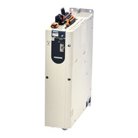
YASKAWA Sigma-7-S Series Product Manual (561 pages)
SERVOPACK with MECHATROLINK-III Communications References, AC Servo Drive
Brand:
YASKAWA
| Category:
Servo Drives
| Size: 10 MB
Table of Contents
Table of Contents
29
Basic Information on
29
Actual Operation
34
The Σ-7 Series
40
Interpreting the Nameplate
41
Part Names
42
Model Designations
44
Interpreting SERVOPACK Model Numbers
44
Interpreting Servomotor Model Numbers
45
Combinations of Servopacks and Servomotors
47
Combinations of Rotary Servomotors and Servopacks
47
Combinations of Direct Drive Servomotors and Servopacks
48
Combinations of Linear Servomotors and Servopacks
49
Combinations of Linear Servomotors and Servopacks
50
Functions
51
Selecting a SERVOPACK
54
Ratings and Specifications
55
Ratings
55
SERVOPACK Overload Protection Characteristics
58
Specifications
59
Functions
61
Block Diagrams
62
SGD7S-R70A, -R90A, and -1R6A
62
Sgd7S-2R8A
62
SGD7S-3R8A, -5R5A, and -7R6A
63
Sgd7S-120A
64
SGD7S-180A and -200A
66
Sgd7S-330A
67
SGD7S-470A and -550A
68
SGD7S-590A and -780A
69
SGD7S-R70F, -R90F, and -2R1F
69
Sgd7S-2R8F
70
External Dimensions
71
Front Cover Dimensions and Connector Specifications
71
SERVOPACK External Dimensions
72
Examples of Standard Connections between Servopacks and Peripheral Devices
78
SERVOPACK Installation
80
Installation Precautions
81
Mounting Types and Orientation
82
Mounting Hole Dimensions
83
Mounting Interval
85
Installing One SERVOPACK in a Control Panel
85
Installing more than One SERVOPACK in a Control Panel
85
Monitoring the Installation Environment
86
Derating Specifications
87
EMC Installation Conditions
88
Wiring and Connecting Servopacks
91
Wiring and Connecting Servopacks
93
General Precautions
93
Countermeasures against Noise
96
Grounding
99
Basic Wiring Diagrams
100
Wiring the Power Supply to the SERVOPACK
102
Terminal Symbols and Terminal Names
102
Wiring Procedure for Main Circuit Connector
105
Power on Sequence
106
Power Supply Wiring Diagrams
107
Wiring Regenerative Resistors
113
Wiring Reactors for Harmonic Suppression
115
Wiring Servomotors
116
Terminal Symbols and Terminal Names
116
Pin Arrangement of Encoder Connector (CN2)
116
Wiring the SERVOPACK to the Encoder
117
Wiring the SERVOPACK to the Holding Brake
123
I/O Signal Connections
124
I/O Signal Connector (CN1) Names and Functions
124
I/O Signal Connector (CN1) Pin Arrangement
126
I/O Signal Wiring Examples
127
I/O Circuits
129
Connecting Safety Function Signals
131
Pin Arrangement of Safety Function Signals (CN8)
131
I/O Circuits
131
Connecting MECHATROLINK Communications Cables
133
Connecting the Other Connectors
134
Serial Communications Connector (CN3)
134
Computer Connector (CN7)
134
Analog Monitor Connector (CN5)
134
Basic Functions that Require Setting before Operation
135
Manipulating Parameters (Pn)
138
Parameter Classification
138
Notation for Parameters
139
Parameter Setting Methods
140
Write Prohibition Setting for Parameters
141
Initializing Parameter Settings
144
MECHATROLINK-III Communications Settings
146
Communications Settings
146
Setting the Station Address
146
Power Supply Type Settings for the Main Circuit and Control Circuit
147
AC Power Supply Input/DC Power Supply Input Setting
147
Single-Phase AC Power Supply Input/Three-Phase AC Power Supply Input Setting
148
Automatic Detection of Connected Motor
149
Motor Direction Setting
150
Setting the Linear Encoder Pitch
151
Writing Linear Servomotor Parameters
152
Selecting the Phase Sequence for a Linear Servomotor
156
Polarity Sensor Setting
158
Polarity Detection
159
Restrictions
159
Using the SV_ON (Servo ON) Command to Perform Polarity Detection
160
Detection
160
Using a Tool Function to Perform Polarity Detection
161
Overtravel and Related Settings
162
Overtravel Signals
162
Setting to Enable/Disable Overtravel
163
Motor Stopping Method for Overtravel
163
Overtravel Warnings
165
Holding Brake
166
Brake Operating Sequence
166
BK (Brake) Signal
168
Output Timing of /BK (Brake) Signal When the Servomotor Is Stopped
169
Output Timing of /BK (Brake) Signal When the Servomotor Is Operating
169
Motor Stopping Methods for Servo off and Alarms
171
Stopping Method for Servo off
172
Servomotor Stopping Method for Alarms
172
Motor Overload Detection Level
174
Detection Timing for Overload Warnings (A.910)
174
Detection Timing for Overload Warnings
174
Detection Timing for Overload Alarms (A.720)
175
Electronic Gear Settings
176
Electronic Gear Ratio Settings
177
Electronic Gear Ratio Setting Examples
181
Resetting the Absolute Encoder
182
Precautions on Resetting
182
Preparations
182
Applicable Tools
183
Operating Procedure
183
Setting the Origin of the Absolute Encoder
185
Absolute Encoder Origin Offset
185
Setting the Origin of the Absolute Linear Encoder
185
Setting the Regenerative Resistor Capacity
188
Σ-V Compatible Function and Settings
189
Setting the Communications Interface Compatibility Selection
189
Setting the Encoder Resolution Compatibility Selection
189
Application Functions
190
I/O Signal Allocations
194
Input Signal Allocations
194
Output Signal Allocations
195
I/O Signal Allocations
195
ALM (Servo Alarm) Signal
197
WARN (Warning) Signal
198
TGON (Rotation Detection) Signal
198
S-RDY (Servo Ready) Signal
199
V-CMP (Speed Coincidence Detection) Signal
200
COIN (Positioning Completion) Signal
201
NEAR (Near) Signal
202
Speed Limit During Torque Control
203
Operation for Momentary Power Interruptions
205
SEMI F47 Function
206
Setting the Motor Maximum Speed
208
Encoder Divided Pulse Output
209
Encoder Divided Pulse Output Signals
209
Setting for the Encoder Divided Pulse Output
214
Software Limits
216
Setting to Enable/Disable Software Limits
216
Setting the Software Limits
216
Software Limit Check for References
216
Selecting Torque Limits
217
Internal Torque Limits
217
External Torque Limits
218
CLT (Torque Limit Detection) Signal
221
Absolute Encoders
222
Connecting an Absolute Encoder
223
Structure of the Position Data of the Absolute Encoder
223
Output Ports for the Position Data from the Absolute Encoder
224
Reading the Position Data from the Absolute Encoder
225
Transmission Specifications
226
Calculating the Current Position in Machine Coordinates
226
Alarm Output from Output Ports for the Position Data from the Absolute Encoder
227
Multiturn Limit Setting
228
Multiturn Limit Disagreement Alarm (A.CC0)
229
Absolute Linear Encoders
232
Connecting an Absolute Linear Encoder
232
Structure of the Position Data of the Absolute Linear Encoder
232
Output Ports for the Position Data from the Absolute Linear Encoder
233
Linear Encoder
233
Reading the Position Data from the Absolute Linear Encoder
234
Transmission Specifications
234
Calculating the Current Position in Machine Coordinates
235
Alarm Output from the Output Ports for the Position Data from the Absolute Linear Encoder
236
Software Reset
237
Preparations
237
Applicable Tools
237
Operating Procedure
238
Initializing the Vibration Detection Level
240
Preparations
240
Applicable Tools
241
Operating Procedure
241
Related Parameters
243
Adjusting the Motor Current Detection Signal Offset
244
Automatic Adjustment
244
Manual Adjustment
246
Forcing the Motor to Stop
248
FSTP (Forced Stop Input) Signal
248
Stopping Method Selection for Forced Stops
248
Resetting Method for Forced Stops
250
Overheat Protection
251
Connecting the Overheat Protection Input (TH) Signal
251
Connecting the Overheat Protection Input (TH)
251
Overheat Protection Selection
252
Trial Operation and Actual Operation
253
Flow of Trial Operation
254
Flow of Trial Operation for Rotary Servomotors
254
Flow of Trial Operation for Linear Servomotors
256
Inspections and Confirmations before Trial Operation
258
Trial Operation for the Servomotor Without a Load
259
Preparations
259
Applicable Tools
260
Operating Procedure
260
Trial Operation with MECHATROLINK-III Communications
262
Trial Operation with the Servomotor Connected to the Machine
264
Precautions
264
Preparations
264
Operating Procedure
265
Convenient Function to Use During Trial Operation
266
Program Jogging
266
Origin Search
271
Test Without a Motor
273
Operation Using MECHATROLINK-III Commands
278
Tuning
279
Overview and Flow of Tuning
282
Tuning Functions
283
Diagnostic Tool
284
Monitoring Methods
285
Precautions to Ensure Safe Tuning
286
Overtravel Settings
286
Torque Limit Settings
286
Setting the Position Deviation Overflow Alarm Level
286
Alarm Level
286
Vibration Detection Level Setting
288
Setting the Position Deviation Overflow Alarm Level at Servo on
288
Setting the Position Deviation Overflow Alarm Level at Servo on
289
Tuning-Less Function
290
Application Restrictions
290
Operating Procedure
291
Troubleshooting Alarms
292
Parameters Disabled by Tuning-Less Function
293
Automatically Adjusted Function Setting
293
Related Parameters
293
Estimating the Moment of Inertia
294
Outline
294
Restrictions
294
Applicable Tools
295
Operating Procedure
295
Autotuning Without Host Reference
302
Outline
302
Restrictions
303
Applicable Tools
304
Operating Procedure
304
Operating Procedure
306
Troubleshooting Problems in Autotuning Without a Host Reference
308
Automatically Adjusted Function Settings
310
Related Parameters
312
Autotuning with a Host Reference
313
Outline
313
Restrictions
314
Applicable Tools
314
Operating Procedure
314
Troubleshooting Problems in Autotuning with a Host Reference
318
Automatically Adjusted Function Settings
318
Related Parameters
319
Custom Tuning
320
Outline
320
Preparations
320
Applicable Tools
321
Operating Procedure
321
Automatically Adjusted Function Settings
327
Tuning Example for Tuning Mode 2 or 3
327
Related Parameters
328
Anti-Resonance Control Adjustment
329
Outline
329
Preparations
329
Applicable Tools
330
Operating Procedure
330
Related Parameters
332
Suppressing Different Vibration Frequencies with Anti-Resonance Control
332
Vibration Suppression
334
Outline
334
Preparations
335
Applicable Tools
335
Operating Procedure
335
Setting Combined Functions
337
Related Parameters
337
Speed Ripple Compensation
338
Outline
338
Setting up Speed Ripple Compensation
338
Setting Parameters
342
Additional Adjustment Functions
344
Gain Switching
344
Gain Switching
345
Friction Compensation
348
Gravity Compensation
350
Current Control Mode Selection
351
Current Gain Level Setting
352
Speed Detection Method Selection
352
Speed Feedback Filter
352
Backlash Compensation
353
Manual Tuning
359
Tuning the Servo Gains
359
Compatible Adjustment Functions
370
Diagnostic Tools
374
Mechanical Analysis
374
Mechanical Analysis
375
Easy FFT
376
Easy FFT
377
Monitoring
380
Monitoring Product Information
381
Items that You Can Monitor
381
Operating Procedures
381
Monitoring SERVOPACK Status
382
Servo Drive Status
382
Monitoring Status and Operations
382
I/O Signal Monitor
384
Monitoring Machine Operation Status and Signal Waveforms
385
Items that You Can Monitor
385
Using the Sigmawin
386
Using the Analog Monitors
388
Using the Analog Monitors
390
Monitoring Product Life
392
Items that You Can Monitor
392
Operating Procedure
393
Preventative Maintenance
394
Alarm Tracing
395
Data for Which Alarm Tracing Is Performed
395
Applicable Tools
395
Fully-Closed Loop Control
396
Fully-Closed System
397
SERVOPACK Commissioning Procedure
398
Parameter Settings for Fully-Closed Loop Control
400
Control Block Diagram for Fully-Closed Loop Control
400
Setting the Motor Direction and the Machine Movement Direction
401
Setting the Number of External Encoder Scale Pitches
402
Setting the PAO, PBO, and PCO (Encoder Divided Pulse Output) Signals
402
External Absolute Encoder Data Reception Sequence
403
Electronic Gear Setting
403
Alarm Detection Settings
404
Analog Monitor Signal Settings
405
Setting to Use an External Encoder for Speed Feedback
405
Introduction to the Safety Functions
407
Safety Functions
407
Precautions for Safety Functions
407
Hard Wire Base Block (HWBB)
408
Risk Assessment
409
Hard Wire Base Block (HWBB) State
410
Resetting the HWBB State
411
Related Commands
412
Detecting Errors in HWBB Signal
412
HWBB Input Signal Specifications
412
Operation Without a Host Controller
413
S-RDY (Servo Ready Output) Signal
413
BK (Brake Output) Signal
414
Stopping Methods
414
ALM (Servo Alarm) Signal
414
EDM1 (External Device Monitor)
415
EDM1 Output Signal Specifications
415
Applications Examples for Safety Functions
416
Connection Example
416
Failure Detection Method
416
Procedure
417
Validating Safety Functions
418
Connecting a Safety Function Device
419
Maintenance
420
Inspections and Part Replacement
421
Inspections
421
Guidelines for Part Replacement
421
Replacing the Battery
422
Alarm Displays
424
List of Alarms
424
List of Alarms
425
Troubleshooting Alarms
430
Resetting Alarms
462
Displaying the Alarm History
463
Clearing the Alarm History
464
Resetting Alarms Detected in Option Modules
465
Resetting Motor Type Alarms
467
Warning Displays
468
List of Warnings
468
Troubleshooting Warnings
470
Monitoring Communications Data During Alarms or Warnings
477
Troubleshooting Based on the Operation and Conditions of the Servomotor
478
Parameter Lists
488
List of Servo Parameters
489
Interpreting the Parameter Lists
489
List of Servo Parameters
490
List of MECHATROLINK-III Common Parameters
529
Interpreting the Parameter Lists
529
List of MECHATROLINK-III Common Parameters
530
Parameter Recording Table
538
Appendices
550
Interpreting Panel Displays
551
Interpreting Status Displays
551
Alarm and Warning Displays
551
Hard Wire Base Block Active Display
551
Overtravel Display
551
Forced Stop Display
551
Corresponding SERVOPACK and Sigmawin+ Function Names
552
Corresponding SERVOPACK Utility Function Names
552
Corresponding SERVOPACK Monitor Display Function Names
553
Advertisement
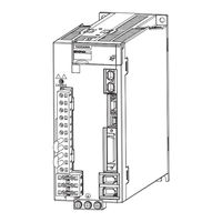
YASKAWA Sigma-7-S Series Product Manual (111 pages)
SERVOPACK with Hardware Option Specifications Dynamic Brake
Brand:
YASKAWA
| Category:
Servo Drives
| Size: 2 MB
Table of Contents
About this Manual
3
Finding Information
3
Related Documents
5
Using this Manual
12
Safety Precautions
15
Warranty
25
Compliance with UL Standards, EU Directives, and Other Safety Standards
27
Table of Contents
30
About the Dynamic Brake Hardware Option Specifications
34
What Is Dynamic Braking
34
Capabilities of Servopacks that Support the Dynamic Brake Hardware Option Specifications
34
Interpreting the Nameplate
35
Part Names
36
SGD7S-R70A to -2R8A, SGD7S-R70F to -2R8F, and SGD7W-1R6A to -2R8A
36
SGD7S-3R8A to -330A
36
SGD7S-470A to -780A
37
SGD7W-5R5A and -7R6A
37
Model Designations
38
Interpreting Σ-7S SERVOPACK Model Numbers
38
Interpreting Σ-7W SERVOPACK Model Numbers
39
Selecting a SERVOPACK
40
Combinations of Servomotors and Servopacks
41
2.1.1 Combinations of Rotary Servomotors and Servopacks
42
Combinations of Direct Drive Servomotors and Servopacks
43
Combinations of Linear Servomotors and Servopacks
45
External Dimensions
47
Selecting a Dynamic Brake Resistor
52
Precautions
53
Selection Flow
54
Determining the Resistance of the Dynamic Brake Resistor
55
How to Determine the Resistance of the Dynamic Brake Resistor
55
Brake Torque and Dynamic Brake Resistance Characteristics
56
Calculating the Energy Consumption of the Dynamic Brake Resistor
65
Presenting the Required Specifications to the Resistor Manufacturer
66
Wiring and Connecting a Dynamic Brake Resistor
67
Wiring and Connecting Servopacks
68
Dynamic Brake Resistor Connections
71
Terminal Symbols and Terminal Names
71
Wire Sizes and Tightening Torques
71
Crimp Terminals and Insulating Sleeves
72
Dynamic Brake Resistor Connector Wiring Procedure
74
Connecting Dynamic Brake Resistors
75
Basic Functions that Require Setting before Operation
77
Outline
78
Motor Stopping Methods for Servo off and Alarms
79
Stopping Method for Servo off
80
Servomotor Stopping Method for Alarms
80
Motor Stopping Method for Overtravel
82
Setting the Energy Consumption and Resistance of the Dynamic Brake Resistor
83
Maintenance
84
Alarms Related to the Dynamic Brake Hardware Option Specifications
85
List of Alarms
85
Troubleshooting Alarms
86
Troubleshooting Based on the Operation and Conditions of the Servomotor
89
Parameter Lists
90
Interpreting the Parameter Lists
91
List of Parameters
92
Appendices
93
Monitor Displays for the Dynamic Brake Hardware Option Specifications
94
Coasting Distance When Stopping with the Dynamic Brake
95
Data for Coasting Distance Calculation
96
Coasting Distance Coefficients
96
Characteristic Impedance
98
Index
109
Revision History
110
Advertisement
Related Products
YASKAWA SERVOPACK Sigma 7 Series
YASKAWA SIGMA-7 Series
YASKAWA Sigma-7W Series
YASKAWA Sigma-7-Series
YASKAWA Sigma-7S SERVOPACK
YASKAWA Sigma-7 SGD7S Series
YASKAWA Sigma-V SGDV-COA
YASKAWA Sigma-II Series
YASKAWA Sigma-V-FT Series
YASKAWA Sigma-V-FT001
YASKAWA Categories
Controller
DC Drives
Servo Drives
Robotics
Control Unit
More YASKAWA Manuals
Login
Sign In
OR
Sign in with Facebook
Sign in with Google
Upload manual
Upload from disk
Upload from URL