Sign In
Upload
Manuals
Brands
YASKAWA Manuals
Servo Drives
SIGMA-7 Series
User Manuals: YASKAWA SIGMA-7 Series Servo Motor
Manuals and User Guides for YASKAWA SIGMA-7 Series Servo Motor. We have
3
YASKAWA SIGMA-7 Series Servo Motor manuals available for free PDF download: Technical Supplement, Product Manual
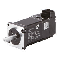
YASKAWA SIGMA-7 Series Technical Supplement (622 pages)
AC Servo Drives and Motors
Brand:
YASKAWA
| Category:
Servo Drives
| Size: 72 MB
Table of Contents
Table of Contents
19
Rotary Servo Motors SGMMV
22
Sgm7J
36
Sgm7A
72
Sgm7P
134
Sgm7G
152
Direct Drive Servo Motors
207
SGM7F (with Core, Inner Rotor)
208
SGM7D (with Core, Outer Rotor)
224
SGMCS (Small Capacity, Coreless or Medium Capacity, with Core)
252
Linear Servo Motors
277
SGLFW2 (Models with F-Type Iron Cores, 200V)
278
SGLFW2 (Models with F-Type Iron Cores, 400V)
306
SGLG (Coreless Models)
326
SGLT (Models with T-Type Iron Cores)
356
Recommended Linear Encoders and Cables
386
SGLFW (Earlier Models with F-Type Iron Cores)
410
Linear Stages
436
ST2F Sigma Trac II Linear Stages
436
Servopacks
441
Single-Axis Analog Voltage/Pulse Train Reference Servopacks
442
Single-Axis MECHATROLINK-III Communications Reference Servopacks
452
Single-Axis Ethercat Communications Reference Servopacks
466
Two-Axis MECHATROLINK-III Communications Reference Servopacks
482
Two-Axis Ethercat Communications Reference Servopacks
496
SERVOPACK External Dimensions
502
Option Modules
518
Feedback Option Module
518
Safety Option Module
524
Sigma-7Siec Option
528
Mp2600Iec Option
530
Sigmalogic7 Compact Option
538
FT19 Option - Less Deviation Control
540
FY79 Option - Built-In Indexer
542
FT81 Option - Support for Harmonic Drive SHA Series Actuators
544
FT82/83 Option - Support for SGM7D Direct Drive Motor
546
Advertisement
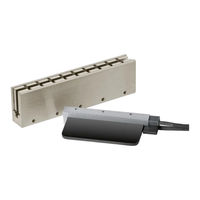
YASKAWA SIGMA-7 Series Product Manual (187 pages)
Linear Servomotor
Brand:
YASKAWA
| Category:
Servo Drives
| Size: 3 MB
Table of Contents
Table of Contents
26
Servomotor Part Names
31
SGLG Servomotors
31
SGLF Servomotors
31
SGLT Servomotors
31
Interpreting the Nameplates
32
Moving Coils
32
Magnetic Ways
32
Outline of Model Designations
33
Servomotors
33
Servopacks
33
Combinations of Servomotors and Servopacks
34
Capacity Selection
36
Selecting the Servomotor Capacity
37
Specifications, Ratings, and External Dimensions of Sglg Servomotors
39
Model Designations
40
Moving Coil
40
Magnetic Way
41
Precautions on Moving Coils with Polarity Sensors (Hall Sensors)
42
Ratings and Specifications
43
Specifications: with Standard-Force Magnetic Way
43
Ratings: with Standard-Force Magnetic Way
44
Force-Motor Speed Characteristics
45
Servomotor Overload Protection Characteristics
46
Specifications: with High-Force Magnetic Way
47
Ratings: with High-Force Magnetic Way
47
Force-Motor Speed Characteristics
48
Servomotor Overload Protection Characteristics
49
Servomotor Overload Protection
49
Characteristics
49
External Dimensions
50
Sglgw-30
50
Sglgw-40
50
Sglgw-60
53
Sglgw-40
54
Sglgw-90
54
Sglgw-60
58
Sglgw-90
61
Selecting Cables
63
Cable Configurations
63
Specifications, Ratings, and External Dimensions of Sglf Servomotors
65
Model Designations
67
SGLFW2 Models
67
SGLFW Models
68
Precautions on Moving Coils with Polarity Sensors (Hall Sensors)
69
Ratings and Specifications: SGLFW2 Models
70
Specifications
70
Ratings: Self-Cooled Models
71
Force-Motor Speed Characteristics: Self-Cooled Models
73
Ratings: Water-Cooled Models
74
Force-Motor Speed Characteristics: Water-Cooled Models
75
Servomotor Overload Protection Characteristics
76
Ratings and Specifications: SGLFW Models
77
Specifications
77
Ratings
78
Force-Motor Speed Characteristics
79
Servomotor Overload Protection Characteristics
80
External Dimensions
81
Sglfw2-30
82
Sglfw2-45
86
4.4 External Dimensions
88
Sglfw2-45
88
SGLFW2-90: Self-Cooled Models
89
SGLFW2-90: Water-Cooled Models
92
4.4.4 SGLFW2-90: Water-Cooled Models
93
SGLFW2-90: Self-Cooled and Water-Cooled Models
94
Sglfw2-1D
95
Sglfw-20
98
Sglfw-35
100
Sglfw-35
102
Sglfw-50
104
4.4.10 Sglfw-1Z
106
Selecting Cables
109
Cable Configurations
109
Linear Servomotor Main Circuit Cables
110
Specifications, Ratings, and External Dimensions of Sglt Servomotors
112
Model Designations
113
Moving Coil
113
Magnetic Way
114
Precautions on Moving Coils with Polarity Sensors (Hall Sensor)
115
Ratings and Specifications
116
Specifications
116
Ratings
117
Force-Motor Speed Characteristics
118
Servomotor Overload Protection Characteristics
120
External Dimensions
121
SGLTW-20: Standard Models
121
SGLTW-35: Standard Models
124
SGLTW-35H: High-Efficiency Models
127
SGLTW-40: Standard Models
129
SGLTW-50: High-Efficiency Models
132
SGLTW-80: Standard Models
134
Selecting Cables
137
Cable Configurations
137
Linear Servomotor Main Circuit Cables
138
Equipment Design Precautions
140
Influence of Magnetic Attraction
141
SGLF Servomotors
141
Influence of Magnetic Way Leakage Flux
143
SGLG Servomotors
143
SGLF Servomotors
143
SGLT Servomotors
144
Special Precautions for SGLT Servomotors
145
Precautions for Water-Cooled Models
146
Servomotor Installation
148
Installation Conditions
149
Installation Environment
149
Installation Orientation
149
Installation Procedure
150
SGLG Servomotors (Coreless Models)
150
SGLF Servomotors (Models with F-Type Iron Cores)
152
SGLT Servomotors (Models with T-Type Iron Cores)
157
Servomotor Temperature Increase
163
Connecting Linear Encoders
164
Installation Conditions for Linear Encoders
165
SGLG Servomotors
165
Mounting Linear Encoders
167
Linear Encoders from Heidenhain Corporation
167
Linear Encoders from RSF Elektronik Gmbh
167
Linear Encoders from Renishaw PLC
167
Linear Encoders from RLS D.o.o
167
Absolute Linear Encoders from Mitutoyo Corporation
168
Linear Encoders from Magnescale Co., Ltd
168
Adjusting Linear Encoders
169
Selecting Cables
171
Linear Encoder Cables
171
Serial Converter Unit Cables
171
Sensor Cables
172
9.1.4 Serial Converter Units
175
Wiring Servomotors and Servopacks
176
Wiring Precautions
176
Wiring Procedure
179
Periodic Inspections
183
10.1.1 Linear Servomotor Inspections
183
Linear Encoder Inspections
184
Disposing of Servomotors
185
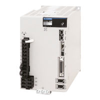
YASKAWA SIGMA-7 Series Product Manual (210 pages)
AC Servo Drive
Brand:
YASKAWA
| Category:
Controller
| Size: 1 MB
Table of Contents
About this Manual
3
Table Synchronized Stopping
3
Outline of Manual
3
Related Documents
5
Technical Terms Used in this Manual
12
Differences in Terms for Rotary Servomotors and Linear Servomotors
12
Using this Manual
12
Safety Precautions
15
Storage Precautions
17
Transportation Precautions
17
Wiring Precautions
18
Installation Precautions
18
Operation Precautions
20
Maintenance and Inspection Precautions
21
Troubleshooting Precautions
22
Warranty
24
Compliance with UL Standards and EU Directives
26
Table of Contents
28
Basic Information
31
Product Introduction
32
Model Designations
33
Interpreting SERVOPACK Model Numbers
33
Interpreting Servomotor Model Numbers
34
Combinations of Servopacks and Servomotors
35
SERVOPACK Functions
36
Function Application Restrictions
39
Sigmawin
40
SERVOPACK Ratings and Specifications
41
Ratings
42
SERVOPACK Overload Protection Characteristics
44
Specifications
45
Position Correction Table
48
Outline
49
Position Correction Table Block Diagram
50
Parameter Settings Related to the Position Correction Table
51
Position Correction Table Enable/Disable
51
Position Correction Axis Selection
51
Position Correction Table-Related Monitor Selection
51
Alarm Related to the Position Correction Table
52
Position Correction Table Settings
53
Measure the Positions Required for the Position Correction Table
53
Position Correction Table Details
54
Setting Method with the Sigmawin+
55
Initializing the Position Correction Table
60
Reading the Position Correction Table from the Servopack
62
Writing the Position Correction Table
63
Reading a Position Correction Table File
64
Saving the Position Correction Table to a Project File
65
Setting Method with the MEM_WR Command
67
Writing the Position Correction Table to Volatile Memory
67
Saving the Position Correction Table to Non-Volatile Memory
68
Details of Settings with MEM_WR (Write Memory: 1EH) Command
70
Command Parameters
71
Command Warnings
71
MECHATROLINK-III Monitoring
72
Monitoring with the Sigmawin+
72
Monitoring with the Digital Operator
72
SVCMD_IO (Servo Command Input Signal) Monitoring
73
Synchronized Stopping
74
Outline
75
Synchronized Stopping Timing Chart
76
Parameter Settings Related to Synchronized Stopping
77
Synchronized Stopping End Speed Setting
77
Adjusting Synchronized Stopping
78
Alarms Related to Synchronized Stopping
79
Warning Related to Synchronized Stopping
80
CSTP_S in the I/O Signal Status Monitor
81
SVCMD_IO (I/O Signal Status) Field
81
Details of I/O Signal Status Bits
81
Servomotor Stopping Method for Alarms
82
Position Deviation between Axes Overflow Detection
83
Outline
84
Parameter Settings Related to Position Deviation between Axes Overflow Detection
85
Alarm Related to Position Deviation between Axes Overflow Detection
86
Warning Related to Position Deviation between Axes Overflow Detection
87
Monitoring
88
Monitoring with the Sigmawin
88
Monitoring with the Digital Operator
88
Maintenance
89
Alarm Displays
90
List of Alarms
90
6.1.1 List of Alarms
92
Troubleshooting Alarms
95
Warning Displays
124
List of Warnings
124
6.2.1 List of Warnings
126
Troubleshooting Warnings
127
Troubleshooting Based on the Operation and Conditions of the Servomotor
134
Parameter Lists
144
Interpreting the Servo Parameter Lists
145
Interpreting the MECHATROLINK-III Common Parameter Lists
146
List of Servo Parameters
147
7.3 List of MECHATROLINK-III Common Parameters
199
Index
207
Revision History
208
Advertisement
Advertisement
Related Products
YASKAWA Sigma-7-S Series
YASKAWA SERVOPACK Sigma 7 Series
YASKAWA Sigma-7W Series
YASKAWA Sigma-7-Series
YASKAWA Sigma-7S SERVOPACK
YASKAWA Sigma-7 SGD7S Series
YASKAWA Sigma Mini SGMM Series
YASKAWA Sigma SGM Series
YASKAWA Sigma-III SGMAS
YASKAWA Sigma-V SGDV-J Series
YASKAWA Categories
Controller
DC Drives
Servo Drives
Robotics
Control Unit
More YASKAWA Manuals
Login
Sign In
OR
Sign in with Facebook
Sign in with Google
Upload manual
Upload from disk
Upload from URL