Sign In
Upload
Manuals
Brands
Mitsubishi Manuals
Controller
MELSEC-L Series
Mitsubishi MELSEC-L Series Controller Manuals
Manuals and User Guides for Mitsubishi MELSEC-L Series Controller. We have
8
Mitsubishi MELSEC-L Series Controller manuals available for free PDF download: User Manual, Programming Manual, Quick Start Manual
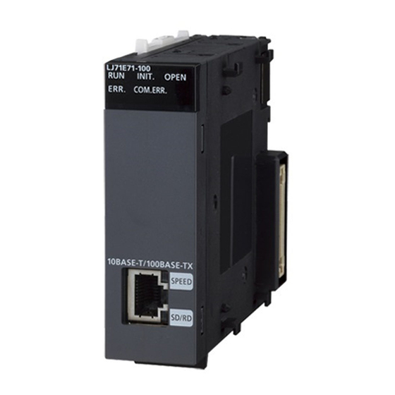
Mitsubishi MELSEC-L Series User Manual (428 pages)
Communication Module
Brand:
Mitsubishi
| Category:
Controller
| Size: 10 MB
Table of Contents
Safety Precautions
3
Conditions of Use for the Product
8
Introduction
9
Compliance with the Emc and Low Voltage Directives
10
Relevant Manuals
11
Table of Contents
13
Terms
19
Packing List
21
1 Serial Communication Module Functionality
24
2 Part Names
27
3 Specifications
29
General Specifications
29
Performance Specifications
29
Number of Parameter Settings
31
Function List
32
Basic Functions
32
Additional Functions
33
List of Input/Output Signals
35
4 Procedures Prior to Operation
37
5 System Configuration
39
Overall Configuration
39
Applicable Systems
41
Restrictions When the C24 Is Installed to the Head Module
41
Systems that Can be Configured and Functions
42
6 Setting and Wiring
46
Installation Environment and Position of the Module
46
Handling Precautions
46
External Wiring with RS-232 Interface
47
Connector Specifications
47
Cable Specification
51
Connecting the RS-232 Interface (Full-Duplex Communications)
52
External Wiring with RS-422/485 Interface
54
RS-422/485 Terminal Block Specifications
54
RS-422/485 Cable Specifications
55
Connection Method for the RS-422/485 Interface
56
Precautions When Transferring Data Using RS-422/485 Circuit
61
Enabling or Disabling Echo Back of the RS-422/485 Interface
64
Individual Station Test
66
Rom/Ram/Switch Test
66
Self-Loopback Test
66
Loopback Test
73
7 Settings for the C24
76
Adding the C24 to Projects
77
List of Setting Items for C24
78
Switch Setting
78
Transmission Setting
87
Communication Rate Setting
89
Communication Protocol Setting
90
Station Number Setting
91
Setting and Data Flow in Linked Operation
92
Precautions
94
Various Parameter Settings and Writing to the Flash ROM
95
Parameter Setting
96
Writing to the Flash ROM
98
Auto Refresh
100
Setting Method for Auto Refresh
101
Intelligent Function Module Interrupt Pointer Setting
102
Monitor/Test
104
8 Data Communication Using the MC Protocol
106
Data Communication
107
Formats and Applications of the Data Communication Frames
107
MC Protocol System Setting
108
Support for the LCPU Remote Password Function
109
Utilizing the MX Component
110
9 Data Communication Using the Predefined Protocol
111
Data Communication Procedure
113
Communication Type of Protocols
116
Packet Elements
117
Executing Condition of Predefined Protocol Communication
137
Programming Example
141
System Configuration/Wiring Example
141
Communication Data
142
Communication Settings
143
10 Data Communication Using the Nonprocedural Protocol
151
Data Reception from the External Device
152
Receiving Methods
152
The Receive Area and the Received Data List
156
Sequence Program for Data Reception
161
How to Detect and Check the Reception Errors
164
Receive Data Clear
167
Received Data Count and Receive Complete Code Settings
173
Sending Data to the External Device
176
Transmission Methods
176
Arrangement and Contents of the Transmission Area and the Transmission Data
177
Sequence Program for Transmission Data
179
How to Detect and Confirm Transmission Errors
183
Data Communications Precautions
185
11 Data Communication Using the Bidirectional Protocol
187
Data Reception from the External Device
188
Receiving Methods
188
Arrangement and Contents of the Receive Area and the Receive Data
190
Sequence Program for Data Reception
196
How to Detect and Check the Reception Errors
199
Receive Data Clear
200
Sending Data to the External Device
201
Transmission Methods
201
Arrangement and Contents of the Transmission Area and the Transmission Data
202
Sequence Program for Data Transmission
205
How to Detect and Confirm Transmission Errors
209
Processing When Simultaneous Transmission Performed During Full-Duplex Communication
211
Processing When Simultaneous Transmissions Occur
211
Communication Data Processing When Simultaneous Transmissions Occur
212
Data Communications Precautions
214
12 Dedicated Instructions
216
Dedicated Instruction List and Available Devices
216
G(P).Ondemand
218
G(P).Cprtcl
222
Functional Protocol
229
G(P).Output
230
G.input
234
G(P).Bidout
238
G(P).Bidin
242
G(P).Spbusy
246
ZP.CSET (Receive Data Clear)
248
13 Debug Support Function
252
Circuit Trace
252
Procedure for the Circuit Trace
253
Execution of the Circuit Trace
254
Circuit Trace Option Setting
256
State Monitor
258
Protocol Execution Log Display Storage Function (for Predefined Protocol Only)
263
Checking with GX Works2
264
Checking with the Buffer Memory
266
14 Maintenance and Inspection
267
Inspection Items
267
When Replacing Modules
268
Procedure of C24 Replacement and Re-Registration of Data
268
15 Troubleshooting
270
Checking the Status of the C24
270
Checking the H/W LED Information
271
Checking the H/W Switch Information
275
Reading the RS-232 Control Signal Status
278
Reading the Data Communication Status (Transmission Sequence Status)
279
Reading the Switch Setting Status
280
How to Read the Current Operation Status
282
Error Code
284
How to Check the Error Codes
284
Error Code List
288
A Compatible 1C Frame Communications Error Code List
300
Error Code List While Modem Function Is Used
301
Troubleshooting by Symptom
303
The "RUN" LED Is Turned off
305
The "RD" LED Does Not Blink Even after Message Transmission from the External Device
306
No Response Message Is Returned Even Though the External Device Transmitted a Message and the "RD" LED Blinked
307
Transmission Request Does Not Make the "SD" LED Blink
308
Read Request Signal Does Not Turn on Even Though the External Device Transmitted a Message and the "RD" LED was Blinking
309
The CPRTCL Instruction Execution Is Not Completed Although the "RD" LED Blinked
310
Communication Error "NAK
311
Communication Error "C/N
311
Communication Error "P/S
312
Communication Error "PRO
313
Communication Error "SIO
314
Communication Error "CH1 ERR." or "CH2 ERR
315
Communication Is Intermittent
317
Undecodable Data Are Transmitted or Received
319
Whether the Communication Error Is Caused on the C24 or External Device Is Unclear
320
Communication Is Not Available Via the Modem
321
Communication Is Not Available with the ISDN Sub-Address
321
Constant Cycle Transmission Is Not Performed Normally
322
Condition Agreement Transmission Is Not Performed Normally
322
Data Cannot be Received Due to by an Interrupt Program
322
Data Cannot be Written to the Flash ROM
322
Troubleshooting on the Protocol Setting Data Reading/Writing
323
The "ERR." LED Is Lit
323
Initializing Error Information of the Serial Communication Module
324
Clearing the Programmable Controller CPU Information
328
Appendixes
330
Appendix 1 Buffer Memory
330
Appendix 2 How to Confirm the Serial No. and Function Version
350
Appendix 3 Differences between L Series C24 and Q Series C24
351
Appendix 3.1 Specification Comparisons
351
Appendix 3.2 Precautions for Utilizing Programs
351
Appendix 4 When Using GX Developer or GX Configurator-SC
352
Appendix 4.1 Compatible Software Packages
352
Appendix 4.2 Specification Comparisons
352
Appendix 4.3 Operation Comparison
353
Appendix 4.3.1 Operation of GX Developer
353
Appendix 4.3.2 Operation of GX Configurator-SC
357
Appendix 5 Operation Image and Data Structure of Predefined Protocol
360
Appendix 5.1 Operation Image of each Communication Type of Protocol
360
Appendix 5.1.1 When Communication Type Is "Send Only
360
Appendix 5.1.2 When Communication Type Is "Receive Only
362
Appendix 5.1.3 When Communication Type Is "Send & Receive
364
Appendix 5.2 Verification Operation of Receive Packet
366
Appendix 5.3 Data Examples of Packet Elements
367
Appendix 5.3.1 Length
367
Appendix 5.3.2 Non-Conversion Variable
369
Appendix 5.3.3 Conversion Variable
371
Appendix 5.3.4 Check Code
374
Appendix 5.3.5 Non-Verified Reception
383
Appendix 6 Communication Example When the C24 Is Used Installed to the Head Module
384
Appendix 6.1 Restrictions for Programming
384
Appendix 6.2 System Configuration Example
385
Appendix 6.3 Parameter Setting
390
Appendix 6.3.1 Master Station Setting
390
Appendix 6.3.2 Head Module Setting
392
Appendix 6.4 Execution Program Example of the Predefined Protocol
393
Appendix 6.5 Sending/Receiving Data Using the Nonprocedural or Bidirectional Protocol
398
Appendix 6.5.1 Receiving Data Using the Nonprocedural or Bidirectional Protocol
398
Appendix 6.5.2 Sending Data Using the Nonprocedural or Bidirectional Protocol
401
Appendix 7 Processing Time
405
Appendix 8 ASCII-Code List
408
Appendix 9 Usage Example of MX Component
409
Appendix 10 Setting Value Recording Sheet
416
Appendix 11 External Dimensions
418
Advertisement
Mitsubishi MELSEC-L Series Programming Manual (390 pages)
Brand:
Mitsubishi
| Category:
Controller
| Size: 8 MB
Table of Contents
Safety Precautions
3
Conditions of Use for the Product
4
Revisions
5
Table of Contents
6
Manuals
10
1 Overview
15
Purpose of this Manual
16
Generic Terms and Abbreviations in this Manual
18
Explanation Contents in this Manual
19
Modules and Versions Applicable to Instructions
21
2 Instruction Tables
25
How to Read Instruction Tables
26
5 Module Dedicated Instruction
27
Analog Instruction
27
Serial Communication and Modem Interface Instruction
28
CC-Link Instruction
29
CC-Link IE Controller Network, MELSECNET/H, and Ethernet Instruction
30
2.2.5 Positioning Instruction
32
PID Control Instruction
33
PID Control Instruction (Inexact Differential)
33
PID Control Instruction (Exact Differential)
33
Socket Communication Function Instruction
34
Built-In I/O Function Instruction
35
Positioning Function Dedicated Instruction
35
Counter Function Dedicated Instruction
36
Data Logging Function Instruction
38
OFFGAN Instruction
48
OGLOAD Instruction
50
OGSTOR Instruction
77
Serial Communication and Modem Interface Instruction
106
ONDEMAND Instruction
106
OUTPUT Instruction
110
INPUT Instruction
113
BIDOUT Instruction
116
BIDIN Instruction
119
SPBUSY Instruction
121
CSET Instruction (Receive Data Clear)
122
BUFRCVS Instruction
125
PRR Instruction
127
CSET Instruction (Initial Setting)
131
CSET Instruction (Programmable Controller CPU Monitor)
135
PUTE Instruction
143
GETE Instruction
146
UINI Instruction
149
CC-Link Instruction
154
RIRD Instruction
154
RIWT Instruction
159
RIRCV Instruction
164
RISEND Instruction
168
RIFR Instruction
172
RITO Instruction
174
RLPASET Instruction
176
CC-Link IE Controller Network, MELSECNET/H, and Ethernet Instruction
183
READ Instruction
183
SREAD Instruction
188
WRITE Instruction
192
SWRITE Instruction
199
SEND Instruction
203
5.4.6 RECV Instruction
212
RECVS Instruction
215
REQ Instruction
218
RRUN Instruction
227
RSTOP Instruction
229
RTMRD Instruction
231
RTMWR Instruction
233
REMFR Instruction
236
REMTO Instruction
238
OPEN Instruction
241
CLOSE Instruction
245
BUFRCV Instruction
248
BUFRCVS Instruction
252
BUFSND Instruction
254
ERRCLR Instruction
258
ERRRD Instruction
261
UINI Instruction
264
MRECV Instruction
267
MSEND Instruction
272
ABRST Instruction
279
Positioning Instruction
279
PSTRT Instruction
283
TEACH Instruction
285
PFWRT Instruction
288
PINIT Instruction
290
6 Pid Control Instruction
293
PID Control Instruction (Inexact Differential)
294
6.1.1 PIDINIT Instruction
296
PIDCONT Instruction
299
PIDSTOP Instruction and PIDRUN Instruction
303
PIDPRMW Instruction
304
6.1.4 PIDPRMW Instruction
305
PID Control Instruction (Exact Differential)
308
6.2.1 PIDINIT Instruction
310
PIDCONT Instruction
313
PIDSTOP Instruction and PIDRUN Instruction
318
PIDPRMW Instruction
319
6.2.4 PIDPRMW Instruction
320
7 Socket Communication Function Instruction
323
SOCOPEN Instruction
324
SOCCLOSE Instruction
327
SOCRCV Instruction
330
SOCRCVS Instruction
333
SOCSND Instruction
335
SOCCINF Instruction
338
SOCCSET Instruction
341
SOCRMODE Instruction
344
SOCRDATA Instruction
346
8 Built-In I/O Function Instruction
349
Positioning Function Dedicated Instruction
350
IPPSTRT Instruction
350
IPDSTRT Instruction
351
IPSIMUL Instruction
354
IPOPR Instruction
355
IPJOG Instruction
357
IPABRST Instruction
359
IPSTOP Instruction
361
IPSPCHG Instruction
362
IPTPCHG Instruction
364
Counter Function Dedicated Instruction
366
ICCNTRD Instruction
366
ICRNGWR Instruction
367
ICPREWR Instruction
369
ICLTHRD Instruction
370
ICSMPRD Instruction
371
ICCOVWR Instruction
372
ICFCNT Instruction
373
ICRCNT Instruction
374
ICPLSRD Instruction
375
ICPWM Instruction
376
Data Logging Function Instruction
379
Mitsubishi MELSEC-L Series User Manual (302 pages)
Ethernet Interface Module
Brand:
Mitsubishi
| Category:
Control Unit
| Size: 6 MB
Table of Contents
Safety Precautions
3
Conditions of Use for the Product
7
Compliance with Emc and Low Voltage Directives
8
Introduction
8
Relevant Manuals
9
Table of Contents
10
Manual Page Organization
15
Term
18
Packing List
20
Chapter 1 Features
21
Chapter 2 Part Names
26
Chapter 3 Specifications
28
General Specifications
28
Performance Specifications
28
Function List
30
Use with Other Functions
31
List of I/O Signals
32
Buffer Memory
34
Configuration of the Buffer Memory
34
List of Buffer Memory Addresses
35
Chapter 4 Procedures before Operation
56
Chapter 5 System Configuration
58
Overall System Configuration
58
Network Components
59
Applicable Systems
60
Chapter 6 Installation and Wiring
61
Installation
61
Wiring
62
Chapter 7 Communication Procedure
64
Setting Parameters Required for Communications
65
Parameter List
65
Basic Setting
66
Ethernet Operation Setting
67
Open Setting
69
TCP/IP Communications
72
Establishing a Connection
72
Communication Process
73
Active Open Procedure
75
Passive Open Procedure
77
UDP/IP Communications
80
Communication Process
80
Open Procedure
81
Chapter 8 Connecting Melsoft Products and a Got
83
Applications
83
Data Communication Procedure
84
Chapter 9 MC Protocol Communications
86
Applications
86
Communication Structure
87
Data Communication Procedure
87
Parameter Setting
88
Chapter 10 Communications Using a Fixed Buffer
89
Applications
89
Differences between the "Procedure Exist" and "No Procedure" Control Methods
89
Communication Structure
90
Data Sending Procedure
92
Data Receiving Procedure
94
Data Receiving Using the Main Program (BUFRCV Instruction)
94
Data Receiving Using an Interrupt Program (BUFRCVS Instruction)
97
Parameter Setting
99
Parameter Setting When Using an Interrupt Program
100
Data Format
102
Header
102
Application Data
102
Pairing Open
107
Applications
107
Parameter Setting
108
Broadcast Communications
109
Sending/Receiving Procedures
109
Parameter Setting
111
Precautions
113
Example of Communications Using a Fixed Buffer
114
System Configuration
114
Parameter Setting
114
Program
117
Chapter 11 Communications Using a Random Access Buffer
122
Applications
122
Communication Structure
123
How Data Is Read from a Connected Device
124
How a Connected Device Writes Data
124
Parameter Setting
125
Data Format
126
Header
126
Application Data
127
Examples of Command and Response Formats
131
Precautions When Creating Programs
135
Physical and Logical Addresses of a Random Access Buffer
135
Example of Communications Using a Random Access Buffer
136
Chapter 12 Other Functions
137
Router Relay Function
137
Applications
137
Parameter Settings
137
Communications Using an Auto-Open UDP Port
141
Application
141
Remote Password
142
Application
142
Remote Password Setting Processes (Unlock and Lock Processes)
143
Remote Password Check Procedure
144
Differences in Functions According to the Remote Password Check Status (Enabled/Disabled)
147
Precautions
148
Parameter Settings
150
Hub Connection Status Monitor Function
152
IP Address in Use Detection Function
153
Alive Check Function
155
Chapter 13 Dedicated Instructions
157
List of Dedicated Instructions
157
Parameter Settings for Using Dedicated Instructions
158
When Using Data Link Instructions
158
Precautions for Dedicated Instructions
158
Organization of the Dedicated Instruction Sections
159
Zp.open
160
Zp.close
164
Zp.bufsnd
167
Zp.bufrcv
171
Z.bufrcvs
175
Zp.errclr
177
Zp.errrd
181
Zp.uini
184
Chapter 14 Troubleshooting
191
Before Troubleshooting
191
Troubleshooting Procedure
191
Checking with the Module Error Collection Function
192
Checking the Leds
193
If the RUN LED Turns off
193
If the ERR. LED or COM.ERR. LED Turns on
193
If the SD/RD LED Does Not Flash When Data Is Sent
194
Checking with a Display Unit
195
Troubleshooting by Symptom
196
Communications Cannot be Performed with the Connected Device
196
The E71 Frequently Fails to Receive a Message Sent from the Connected Device
197
A Dedicated Instruction Is Not Completed
197
MC Protocol Communications Cannot be Performed
198
Data Cannot be Sent with Communications Using a Fixed Buffer
199
Data Cannot be Received with Communications Using a Fixed Buffer
200
Communications Using a Random Access Buffer Cannot be Performed
201
An E-Mail Cannot be Sent
202
An E-Mail Cannot be Received
203
Communications Using Data Link Instructions Cannot be Performed
204
Error Code List
205
End Codes Returned to a Connected Device During Data Communications
212
Abnormal Codes Returned During Communications Using an A-Compatible 1E Frame
215
Error Codes Stored in the Buffer Memory
216
Ethernet Diagnostics
239
Checking the Status of the E71 with the System Monitor
240
How to Turn off the COM.ERR. LED
242
Appendices
243
Appendix 1 Processing Time
243
Appendix 2 Port Numbers Used for the E71
247
Appendix 3 Initial Process
248
Appendix 3.1 Setting the Initial Process
248
Appendix 3.2 Reinitialization Process
252
Appendix 4 Line Status Check
258
Appendix 4.1 PING Test
258
Appendix 4
258
Loopback Test
263
Appendix 5 Self-Diagnostic Tests
267
Appendix 5.1 Self-Loopback Test
267
Appendix 5.2 Hardware Test (H/W Test)
268
Appendix 5.2
268
Appendix 6 Differences from Ethernet Modules of Other Series
269
Differences from a Built-In Ethernet Port LCPU
269
Appendix 6
269
Differences from Q Series Modules
269
Differences from Qna/A Series Modules
269
Appendix 7 Sample Program on the Connected Device Side
273
Appendix 7.1 When Visual C++ .NET Is Used
284
Appendix 7.2
284
Appendix 7.2 When Visual Basic ® .NET Is Used
284
Appendix 8 Checking the Serial Number, Function Version, and MAC Address
293
Appendix 9 External Dimension Diagram
294
Appendix 10 ASCII Code List
295
Index
296
Revisions
298
Warranty
299
Advertisement
Mitsubishi MELSEC-L Series Programming Manual (236 pages)
Brand:
Mitsubishi
| Category:
Controller
| Size: 3 MB
Table of Contents
Safety Precautions
3
Conditions of Use for the Product
4
Revisions
5
Table of Contents
8
About Manuals
11
Generic Terms
12
1 General Description
14
Description of SFC Program
15
SFC (MELSAP3) Features
17
2 System Configuration
25
3 Specifications
29
Performance Specifications Related to SFC Programs
29
When the Basic Model QCPU Is Used
29
When the High Performance Model QCPU, Process CPU, Redundant CPU, Universal Model CPU, or LCPU Is Used
31
Performance Specifications of Qnacpu
35
Device List
37
Device List of Basic Model QCPU
37
Device List of High Performance Model QCPU, Process CPU, and Redundant CPU
39
Device List of Universal Model QCPU
41
Device List of LCPU
44
Device List of Qnacpu
45
Processing Time
47
Processing Time for SFC Program
47
Processing Time for S(P).SFCSCOMR Instruction and S(P).SFCTCOMR Instruction
53
Calculating the SFC Program Capacity
56
4 Sfc Program Configuration
59
List of SFC Diagram Symbols
60
Steps
63
Step (Without Step Attribute)
64
Initial Step
66
Dummy Step
67
Coil HOLD Step
67
Operation HOLD Step (Without Transition Check)
70
Operation HOLD Step (with Transition Check)
72
Reset Step R
74
Block START Step (with END Check)
75
Block START Step (Without END Check)
77
End Step
79
Instructions that Cannot be Used with Operation Outputs
81
Transition
82
Serial Transition
83
Selection Transition
85
Parallel Transition
88
Jump Transition
92
Precautions When Creating Sequence Programs for Operation Outputs (Steps) and Transition Conditions
93
Controlling SFC Programs by Instructions (SFC Control Instructions)
96
Step Operation Status Check Instructions (LD, LDI, AND, ANI, OR, ORI)
101
Forced Transition Check Instruction (LD, LDI, AND, ANI, OR, ORI)
104
Block Operation Status Check Instruction (LD, LDI, AND, ANI, OR, ORI)
106
Active Step Batch Readout Instructions (MOV, DMOV)
108
Active Step Batch Readout (BMOV)
111
Block START & END Instructions (SET, RST)
115
Block STOP and RESTART Instructions (PAUSE, RSTART)
117
Step START and END Instructions (SET, RST)
120
Forced Transition EXECUTE & CANCEL Instructions (SET, RST)
125
Active Step Change Instruction (SCHG)
127
Block Switching Instruction (BRSET)
128
SFC Information Devices
130
Block START/END Bit
131
Step Transition Bit
133
Block STOP/RESTART Bit
135
Block STOP Mode Bit
137
Continuous Transition Bit
139
Number of Active Steps" Register
141
Step Transition Watchdog Timer
142
SFC Operation Mode Setting
144
SFC Program Start Mode
145
Block 0 START Condition
147
Output Mode at Block STOP
148
Periodic Execution Block Setting
150
Operation Mode at Double Block START
151
Operation Mode at Transition to Active Step (Double Step START)
152
SFC Comment Readout Instruction
155
SFC Comment Readout Instruction (S(P). SFCSCOMR)
156
SFC Transition Comment Readout Instruction (S(P). SFCTCOMR)
164
5 Sfc Program Processing Sequence
172
Whole Program Processing of Basic Model QCPU
172
Whole Program Processing Sequence
172
Whole Program Processing of High Performance Model QCPU, Process CPU, Redundant CPU, Universal Model QCPU, LCPU, and Qnacpu
173
Whole Program Processing Sequence
173
Execution Type Designation by Instructions
175
SFC Program for Program Execution Management
177
SFC Program Processing Sequence
179
SFC Program Execution
179
Block Execution Sequence
181
Step Execution Sequence
182
Continuous Transition ON/OFF Operation
183
6 Sfc Program Execution
186
SFC Program START and STOP
186
SFC Program Resumptive START Procedure
187
Block START and END
189
Block START Methods
189
Block END Methods
190
Block Temporary Stop and Restart Methods
191
Block STOP Methods
191
Restarting a Stopped Block
194
Step START (Activate) and END (Deactivate) Methods
196
Step START (Activate) Methods
196
Step END (Deactivate) Methods
197
Changing an Active Step Status (Not Available for Basic Model QCPU, Universal Model QCPU, and LCPU)
198
Operation Methods for Continuous Transition
199
Operation at Program Change
200
Operation at Program Change Made by Write to PLC
201
Program Change by Online Change
202
Online Change (Inactive Block)
203
Appendices
210
APPENDIX 1 Special Relay and Special Register List
210
APPENDIX 1.1 Special Relay (SM) List
211
APPENDIX 1.2 Special Register (SD) List
215
APPENDIX 2 MELSAP-II and MELSAP3 Comparison
216
APPENDIX 3 Restrictions on Basic Model QCPU, Universal Model QCPU, and LCPU and Alternative Methods
227
APPENDIX 3.1 Step Transition Watchdog Timer Replacement Method
229
APPENDIX 3.2 Periodic Execution Block Replacement Method
230
APPENDIX 3.3 Forced Transition Bit (Trn) Replacement Method
231
APPENDIX 3.4 Active Step Change Instruction (SCHG) Replacement Method
232
Mitsubishi MELSEC-L Series User Manual (150 pages)
Analog-Digital Converter Module
Brand:
Mitsubishi
| Category:
Controller
| Size: 5 MB
Table of Contents
Safety Precautions
3
Conditions of Use for the Product
6
Introduction
7
Compliance with the Emc and Low Voltage Directives
8
Relevant Manuals
9
Table of Contents
10
Manual Page Organization
13
Packing List
16
Terms
16
Chapter 1 A/D Converter Module
17
Application
17
Features
18
Chapter 2 Part Names
19
Chapter 3 Specifications
21
General Specifications
21
Performance Specifications
22
Number of Parameter Settings
23
Function List
24
I/O Signal List
25
List of Buffer Memory Addresses
26
Chapter 4 Procedures before Starting the Operation
32
Chapter 5 System Configuration
34
Overall System Configuration
34
Applicable System
34
Chapter 6 Installation and Wiring
36
Installation Environment and Installation Position
36
Terminal Block
37
Wiring
39
External Wiring
40
Chapter 7 Various Settings
41
Addition of Modules
41
Switch Setting
42
Parameter Setting
43
Auto Refresh
45
Offset/Gain Setting
46
Chapter 8 Functions
49
Digital Data Details
49
A/D Conversion Enable/Disable Function
50
A/D Conversion Method
50
Conversion Speed Switch Function
54
Maximum and Minimum Values Hold Function
54
Input Signal Error Detection Function
55
Warning Output Function (Process Alarm)
58
Scaling Function
61
Error Log Function
64
Module Error Collection Function
66
Error Clear Function
67
Saving and Restoring Offset/Gain Values
68
Chapter 9 Display Unit
73
Display Unit
73
Menu Transition
73
List of Setting Value Change Screens
75
Checking and Clearing Errors
80
Chapter 10 Programming
82
Procedure for Programming
82
When Using the Module in a Standard System Configuration
83
Chapter 11 Troubleshooting
89
Checking on the Module Detailed Information
89
Checking by Latest Error Code (Un\G19)
90
Checking on the Module Error Collection Function
90
Error Code List
91
Alarm Code List
93
Troubleshooting
93
Checking the Status of the A/D Converter Module by the System Monitor
96
Appendices
97
Appendix 1 Details of I/O Signals
97
Appendix 1.1 Input Signal
97
Appendix 1.2 Output Signal
102
Appendix 2 Details of Buffer Memory Addresses
104
Appendix 3 I/O Conversion Characteristic of A/D Conversion
116
Appendix 4 A/D Conversion Accuracy
119
Appendix 5 Dedicated Instruction
120
Appendix 5.1 Instruction List
120
Appendix 5.2 G(P).OFFGAN
121
Appendix 5.3 G(P).OGLOAD
123
Appendix 5.4 G(P).OGSTOR
127
Appendix 6 Checking Serial Number and Function Version
131
Appendix 7 Differences with Q Series
131
Appendix 7.1 Precautions for Applying Q Series Sequence Program
132
Appendix 8 When Using GX Developer or GX Configurator-AD
134
Appendix 8.1 Operation of GX Developer
134
Appendix 8.2 Operation of GX Configurator-AD
140
Appendix 9 External Dimensions
142
Index
143
Instruction Index
145
Revisions
146
Warranty
147
Mitsubishi MELSEC-L Series Programming Manual (108 pages)
Mitsubishi Programmable Controller
Brand:
Mitsubishi
| Category:
Controller
| Size: 2 MB
Table of Contents
Safety Precautions
3
Conditions of Use for the Product
4
Revisions
5
Table of Contents
6
Manuals
8
1 Overview
10
Purpose of this Manual
10
Overview
10
Generic Terms and Abbreviations in this Manual
13
Features of Structured Programs
14
Applicable CPU Modules
15
Compatible Software Package
15
2 Structured Design of Sequence Programs
17
What Is a Hierarchical Sequence Program
18
What Is a Structured Sequence Program
19
3 Procedure for Creating Programs
21
3.1 Procedure for Creating Sequence Programs in Structured Project
22
4 Program Configuration
23
Overview of Program Configuration
24
Project
25
Program Files
25
Tasks
26
Pous
27
Types of POU
27
Program Blocks
28
Functions
28
Function Blocks
29
Ladder Blocks
30
Programming Languages for Pous
31
Functions and Function Blocks
32
EN and ENO
35
Labels
37
Global Labels
37
Local Labels
37
Label Classes
38
Setting Labels
39
Data Types
40
Expressing Methods of Constants
42
Method for Specifying Data
43
Bit Data
44
Word (16 Bits) Data
45
Double Word (32 Bits) Data
47
Single-Precision Real/Double-Precision Real Data
49
String Data
52
Time Data
53
Arrays
54
Structures
56
Device and Address
57
Device
57
Address
58
Correspondence between Devices and Addresses
59
Index Setting
62
Libraries
74
User Libraries
75
Precautions on Assigning a Name
76
5 Writing Programs
77
ST Language
78
Standard Format
78
Operators in ST Language
79
Syntaxes in ST Language
80
Calling Functions in ST Language
85
Calling Function Blocks in ST Language
86
Structured Ladder Language
87
Standard Format
87
Ladder Symbols in Structured Ladder Language
88
Appendix
91
Appendix 1 Correspondence between Generic Data Types and Devices App
92
Appendix 2 Character Strings that Cannot be Used in Label Names and Data Names App
97
Appendix 3 Recreating Ladder Programs App
98
Appendix 3.1 Procedure for Creating a Structured Program
98
Appendix 3.2 Example of Creating a Structured Program
99
Mitsubishi MELSEC-L Series User Manual (90 pages)
CC-Link/LT Master Module
Brand:
Mitsubishi
| Category:
Controller
| Size: 5 MB
Table of Contents
Safety Precautions
3
Conditions of Use for the Product
6
Compliance with Emc and Low Voltage Directives
7
Introduction
7
Relevant Manuals
8
Table of Contents
10
Manual Page Organization
12
Terms
13
Packing List
14
CHAPTER 1 CHARACTERISTICS of CC-Link/Lt SYSTEM
15
CC-Link/Lt System
15
Features
16
Chapter 2 Part Names
17
Chapter 3 Specifications
19
General Specifications
19
Performance Specifications
20
I/O Signal List
22
Buffer Memory List
24
Chapter 4 Procedure before Operation
25
Chapter 5 System Configuration
27
Overall Configuration
27
Applicable System
29
Precautions for System Configuration
29
Chapter 6 Installation and Wiring
34
Installation Environment and Installation Position of the Module
34
Point Mode Setting and the Number of Occupied I/O Points Setting
35
Connecting Modules with Cables Connecting Modules Using Connection Cables
38
Connecting a Dedicated Flat Cable Connector
39
Connecting a VCTF Cable Connector/Flexible Cable Connector
42
Using Cables of Different Types Together
45
Connecting Terminating Resistors
48
Checking Wiring
49
Installing/Removing a Remote Station
50
Last Station Number Setting
51
Chapter 7 Programming
53
System Configuration Example
53
Devices Available for Users
54
Program Example
54
Chapter 8 Troubleshooting
55
Condition of each Station in Case of Failure Station Status if an Error Occurs
55
Visual Check
56
Troubleshooting of the Master Station
57
The RUN LED Does Not Turn on
57
The L RUN LED Does Not Turn on
57
The ERR. LED Is on or Flashing
58
The L ERR. LED Is on or Flashing
59
Troubleshooting of Remote I/O Stations
61
The PW LED Does Not Turn on
61
The L RUN LED Does Not Turn on
62
The L ERR. LED Is on or Flashing
62
I/O Errors in Remote I/O Stations
63
Input Data Cannot be Read from a Remote I/O Station
63
Data Cannot be Output from a Remote I/O Station
63
Error Codes
64
CC-Link/Lt Diagnostics
65
Self-Loopback Test
69
Appendices
70
Appendix 1 Details of Buffer Memory Areas
70
Appendix 2 Check Methods of Serial Number and Function Version
74
Appendix 3 Data Link Processing Time
74
Appendix 4 Difference between L Series and Q Series
76
Appendix 5 I/O Assignment Tables
77
Appendix 6 External Dimensions
80
Index
82
Revisions
84
Warranty
85
Mitsubishi MELSEC-L Series Quick Start Manual (52 pages)
Brand:
Mitsubishi
| Category:
Controller
| Size: 17 MB
Table of Contents
How to Read this Guide
3
Related Manuals
8
Preparing for Operation
10
System Configuration
11
Mounting Modules
12
Checking Power Supply
17
Writing Programs
24
Checking Operation
27
Frequently-Used Functions
30
Checking Errors
43
Monitoring System Status
45
Advertisement
Related Products
Mitsubishi MELSEC L Series
Mitsubishi MELSEC-l
Mitsubishi MELSEC-L60AD4
Mitsubishi Melsec A series
Mitsubishi MELSEC iQ-R series
Mitsubishi MELSEC QCPU
Mitsubishi MELSEC-QX10-TS
Mitsubishi MELSEC-QX70-H
Mitsubishi MELSEC-F FX2C
Mitsubishi MELSEC-QX48Y57
Mitsubishi Categories
Air Conditioner
Controller
Projector
Automobile
Engine
More Mitsubishi Manuals
Login
Sign In
OR
Sign in with Facebook
Sign in with Google
Upload manual
Upload from disk
Upload from URL