Sign In
Upload
Manuals
Brands
Mitsubishi Electric Manuals
Controller
MELSEC iQ-RJ71EN71
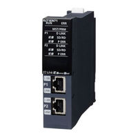
Mitsubishi Electric MELSEC iQ-RJ71EN71 Manuals
Manuals and User Guides for Mitsubishi Electric MELSEC iQ-RJ71EN71. We have
3
Mitsubishi Electric MELSEC iQ-RJ71EN71 manuals available for free PDF download: User Manual
Mitsubishi Electric MELSEC iQ-RJ71EN71 User Manual (416 pages)
Ethernet
Brand:
Mitsubishi Electric
| Category:
Controller
| Size: 16.56 MB
Table of Contents
3
Safety Precautions
10
Conditions of Use for the Product
10
Introduction
11
Table of Contents
15
Relevant Manuals
16
Terms
19
Chapter 1 Functions
19
Connection with MELSOFT Product and GOT
19
Connection Via a Hub
26
Direct Connection
29
SLMP Communications
29
Applications
30
Communication Structure
30
Data Communication Procedures
32
List of Valid Commands
34
Communications Using the Predefined Protocol
34
Applicable Connections
35
Data Communication Procedures
42
Protocol Communication Type
43
Packet Elements
50
Execution Conditions of Predefined Protocol Communications
52
Example of Predefined Protocol Communications
61
Socket Communications
61
Setting Procedure
62
Applicable Dedicated Instructions
62
Applicable Connections
63
Communication Structure
64
Communications Using TCP/IP
67
Communications Using UDP/IP
68
Broadcast Communications
69
Precautions
70
Communications Using the Fixed Buffer
70
Differences Between the "Procedure Exist" and "No Procedure" Control Methods
70
Setting Procedure
71
Applicable Dedicated Instructions
71
Applicable Connections
71
Communication Structure
73
Send Procedure
75
Receive Procedure
79
Pairing Open
80
Broadcast Communications
80
Precautions
81
Data Format
86
Example of Communications Using the Fixed Buffer
96
1.6 Communications Using the Random Access Buffer
96
Setting Procedure
97
Communication Structure
97
Procedure for Reading From External Device
98
Procedure for Writing From External Device
99
Physical Address and Logical Address of Random Access Buffer
99
Precautions
99
Data Format
108
Example of Communications with Random Access Buffer
109
Communications Using MODBUS/TCP
110
Automatic Response Function
111
MODBUS Device Assignment Function
117
List of MODBUS Standard Functions
118
Link Dedicated Instruction Communication
118
Applicable Dedicated Instructions
119
Data Communication Procedures
120
File Transfer Function (FTP Server)
121
Data Communication Procedures
123
Files That Can Be Transferred with FTP
124
FTP Command
134
Precautions
137
File Transfer Function (FTP Client)
138
Transferable Files
139
Procedure for Executing the File Transfer Function (FTP Client)
141
Precautions
143
Time Setting Function (SNTP Client)
145
Web Server Function
146
Javascript Objects
160
CGI Object
173
Error Message
175
Security Function
175
IP Filter Function
176
Remote Password
183
Simple CPU Communication Function (CPU Module (Built-In Ethernet Port Part))
184
Setting Procedure
191
Checking the Simple CPU Communication Status
193
Precautions
195
Simple CPU Communication Function (RJ71EN71, Rnencpu (Network Part))
196
Setting Procedure
209
Checking the Simple CPU Communication Status
211
Precautions
213
IP Address Change Function
214
IP Address of the Ethernet-Equipped Module
216
Usage Methods
219
Checking the IP Address
219
Checking the Operating Status
219
Precautions
221
Redundant System Function
221
System Configuration
222
System Switching Operation
223
System Switching Request to the Control System CPU Module
225
Redundant Group Setting
227
Communication Path Bypass Function
228
Both Systems Identical IP Address Setting Function
231
Functions Restricted in a Redundant System
236
Setting Example
243
Chapter 2 Parameter Settings
243
Setting Parameters
243
Basic Settings
244
Own Node Settings
246
External Device Configuration
249
Application Settings
252
Frame Settings
252
Communication Speed
254
FTP Server Settings
255
FTP Client Settings
255
DNS Settings
256
MODBUS/TCP Settings
258
Simple CPU Communication Setting (RJ71EN71, Rnencpu (Network Part))
261
Time Setting
262
Timer Settings for Data Communication
265
Security
265
Gateway Parameter Settings
267
Network/Station No. <-> IP Information Setting
275
Interrupt Settings
275
IP Packet Transfer Setting
276
Network Dynamic Routing
277
Module Operation Mode
278
Redundant System Settings
280
Simple CPU Communication Setting (CPU Module (Built-In Ethernet Port Part))
282
Chapter 3 Troubleshooting
282
Checking with LED
284
Checking the Module Status
288
Checking the Network Status
288
Ethernet Diagnostics
296
Simple CPU Communication Diagnostics
297
Troubleshooting By Symptom
312
List of Error Codes
329
List of Parameter Numbers
331
Event List
333
End Codes Returned to an External Device During Data Communications
335
Appendices
335
Appendix 1 Module Label
336
Appendix 2 I/O Signals
336
List of I/O Signals
338
Appendix 3 Buffer Memory
338
List of Buffer Memory Addresses
357
Details of Buffer Memory Addresses (RJ71EN71, Rnencpu (Network Part))
372
Details of Buffer Memory Addresses (CPU Module (Built-In Ethernet Port Part))
376
Appendix 4 Dedicated Instruction
379
Precautions for Dedicated Instructions
380
Appendix 5 TCP/IP Communications, UDP/IP Communications
380
TCP/IP Communications
385
UDP/IP Communications
387
Appendix 6 Communications with Different Networks
390
Appendix 7 Processing Time
394
Performance List of Simple CPU Communication Function
395
Appendix 8 When Connecting the Module to a Remote Head Module
395
Restricted Functions and Specifications
396
Appendix 9 Port Numbers Used By Ethernet-Equipped Module
397
Appendix 10Operation Image and Data Structure of Predefined Protocol
397
Operation Image of Each Communication Type of Protocol
402
Verification Operation of Receive Packet
403
Example of Packet Element Data
406
Appendix 11 Example of External Device Program
407
Appendix 12How to Turn Off ERR LED
408
Appendix 13Added and Enhanced Functions
410
Index
412
Revisions
413
Warranty
414
Trademarks
Advertisement
Mitsubishi Electric MELSEC iQ-RJ71EN71 User Manual (390 pages)
MELSEC iQ-R Series CC-Link IE Field Network
Brand:
Mitsubishi Electric
| Category:
Controller
| Size: 48.67 MB
Table of Contents
3
Safety Precautions
10
Conditions of Use for the Product
10
Introduction
11
Table of Contents
14
Relevant Manuals
15
Terms
18
1.1 Cyclic Transmission
18
Data Flow and Link Device Assignment
18
Chapter 1 Functions
20
Link Refresh
23
Direct Access to Link Devices
25
Cyclic Data Integrity Assurance
31
Interlink Transmission
31
Sequence Scan Synchronization Specification
33
Input and Output Status Settings When Failure Occurs
34
Output Status Setting for CPU STOP
36
Cyclic Transmission Stop and Restart
37
Transient Transmission
37
Communications Within the Same Network
38
Communications with Different Networks
43
IP Packet Transfer Function
44
System Configuration
45
Setting
50
IP Communication Test
52
Access Range
53
Relay Using CC-Link IE Controller Network
54
Precautions
56
Example of Communications Using the IP Packet Transfer Function
62
Communication Speed
67
Interrupt Request to CPU Module
68
Loopback Function
70
Submaster Function
71
Cyclic Transmission of When the Submaster Function Is Used
75
Transient Transmission of When the Submaster Function Is Used
75
Switch From the Master Station to the Submaster Station
78
Precautions
81
Redundant System Function
81
System Configuration
84
System Switching Operation
91
System Switching Request to the Control System CPU Module
95
Wiring Precautions
96
Functions Restricted in a Redundant System
97
Setting Examples
110
Safety Communication Function
110
System Using the Safety CPU
114
System Using the SIL2 Process CPU
126
Chapter 2 Parameter Settings
126
Setting Parameters
126
Required Settings
128
Station Type
128
Network No
128
Station No
129
Parameter Setting Method
130
Basic Settings
131
Network Configuration Settings
135
Refresh Settings
138
Network Topology
138
Submaster Parameters
138
Operation of Master Station After Reconnection
139
Application Settings
141
Supplementary Cyclic Settings
143
Interrupt Settings
146
IP Address
147
Communication Mode
147
Parameter Name
147
Dynamic Routing
148
Event Reception From Other Stations
149
Module Operation Mode
149
Interlink Transmission Settings
153
Safety Communication Setting
156
Redundant System Settings
157
Chapter 3 Programming
157
Precautions for Programming
161
Communication Example Using the Submaster Function
161
System Configuration Example
163
Setting in the Master Station
166
Setting in the Local Station
167
Setting in the Submaster Station
168
Starting Up the System
169
Checking the Network Status
170
Program Examples
173
Programming for When the Submaster Function Is Used
175
Communication Example of Safety Communication Function
175
System Configuration Example
177
Setting in the Master Station and Remote Device Station
184
Setting in the Local Station
186
Checking the Network Status
187
Program Examples
189
Communication Example of Safety Communication Function Used in Redundant Master Stations
189
System Configuration Example
191
Intelligent Device Station Setting
193
Master Station Setting
201
Checking the Network Status
202
Program Examples
203
Communication Example of Safety Communication Function Used in a Redundant Line
203
System Configuration Example
205
Intelligent Device Station Setting
207
Master Station Setting
215
Checking the Network Status
216
Program Examples
217
Chapter 4 Troubleshooting
217
Checking with LED
221
Checking the Module Status
225
Checking the Network Status
253
Troubleshooting By Symptom
259
List of Error Codes
280
List of Parameter Numbers
281
Event List
284
Appendices
284
Appendix 1 Module Label
285
Appendix 2 I/O Signals
285
List of I/O Signals
285
Details of I/O Signals
287
Appendix 3 Buffer Memory
287
List of Buffer Memory Addresses
290
Details of Buffer Memory Addresses
296
Appendix 4 List of Link Special Relay (SB)
316
Appendix 5 List of Link Special Register (SW)
337
Appendix 6 Dedicated Instruction
339
Precautions for Dedicated Instructions
342
Appendix 7 Processing Time
343
Link Scan Time
345
Master Station Switching Time
345
Cyclic Transmission Delay Time
348
Interlink Transmission Time
349
Transmission Delay Time of Safety Communications
354
Cyclic Data Holding Time When System Switching Occurs
374
Safety Data Holding Time When System Switching Occurs
381
Appendix 8 Differences in Cyclic Transmission Modes
382
Appendix 9 Precautions for When Connecting the Module to the Conventional Product
383
Appendix 10Added and Enhanced Functions
384
Index
386
Revisions
387
Warranty
388
Trademarks
Mitsubishi Electric MELSEC iQ-RJ71EN71 User Manual (110 pages)
Brand:
Mitsubishi Electric
| Category:
Controller
| Size: 15.7 MB
Table of Contents
3
Safety Precautions
11
Conditions of Use for the Product
12
Compliance with Emc and Low Voltage Directives
12
Introduction
13
Table of Contents
15
Relevant Manuals
16
Terms
19
Chapter 1 Part Names
19
Rj71En71
20
Available Combination of Network
21
Network Used and LED Indication
25
CPU Module
26
Available Combination of Network
27
Network Used and LED Indication
28
Rj71Gp21(S)-Sx
30
Rj71Gf11-T2
32
Chapter 2 Specifications
32
Performance Specifications of Ethernet
33
Performance Specifications of CC-Link IE Controller Network
34
Performance Specifications of CC-Link IE Field Network
36
Hardware Specifications
37
Chapter 3 Function List
37
Function List of Ethernet
39
Function List of CC-Link IE Controller Network
42
Function List of CC-Link IE Field Network
46
Chapter 4 Procedures before Operation
48
Chapter 5 System Configuration
49
Ethernet Configuration
50
CC-Link IE Controller Network Configuration
50
When Optical Fiber Cables Are Used
51
When Ethernet Cables Are Used
53
Precautions When Ethernet Cables Are Used
56
CC-Link IE Field Network Configuration
59
Precautions
62
Precautions for System Configuration
63
Chapter 6 Wiring
63
Ethernet Wiring
65
Wiring of CC-Link IE Controller Network
65
Optical Fiber Cable
66
External Power Supply
67
Ethernet Cables
69
Wiring of CC-Link IE Field Network
71
Chapter 7 Communication Examples
71
Communication Examples of Ethernet
71
System Configuration Example
71
Sending Side
73
Receiving Side
75
Program Example
81
Communication Examples of CC-Link IE Controller Network
81
System Configuration Example
82
Setting in the Control Station
85
Setting in the Normal Stations
87
Checking the Network Status
88
Program Example
92
Communication Examples of CC-Link IE Field Network
92
System Configuration Example
94
Setting in the Master Station
97
Setting in the Local Station
99
Checking the Network Status
100
Program Example
102
Appendix
102
Appendix 1 External Dimensions
104
Index
106
Revisions
107
Warranty
108
Trademarks
Advertisement
Share and save
Advertisement
Related Products
Mitsubishi Electric MELSEC iQ-RJ71GF11-T2
Mitsubishi Electric MELSEC iQ-RJ71GP21-SX
Mitsubishi Electric MELSEC iQ-RJ71GP21S-SX
Mitsubishi Electric MELSEC iQ-RJ71EIP91
Mitsubishi Electric MELSEC iQ-RJ71C24
Mitsubishi Electric MELSEC iQ-RJ71C24-R2
Mitsubishi Electric MELSEC iQ-RJ71C24-R4
Mitsubishi Electric MELSEC iQ-R-R16PCPU
Mitsubishi Electric MELSEC iQ-R-R32SFCPU
Mitsubishi Electric MELSEC iQ-R-R6RFM
Mitsubishi Electric Categories
Air Conditioner
Controller
Projector
Inverter
Monitor
More Mitsubishi Electric Manuals
×
Login
Sign In
OR
Sign in with Facebook
Sign in with Google
×
Upload manual
Upload from disk
Upload from URL