KEB COMBIVERT G6 series Installation Manual
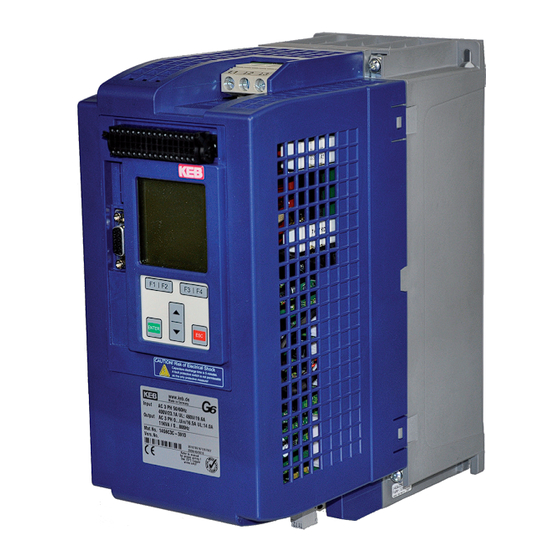
Housing c
power 5.5...11kw
Hide thumbs
Also See for COMBIVERT G6 series:
- Instructions for use manual (54 pages) ,
- Programming manual (32 pages) ,
- Instructions for use manual (54 pages)
Table of Contents
Advertisement
Quick Links
Download this manual
See also:
Programming Manual
Advertisement
Table of Contents

Subscribe to Our Youtube Channel
Related Manuals for KEB COMBIVERT G6 series


Summary of Contents for KEB COMBIVERT G6 series
- Page 1 C O M B I V E R T GB Installation Manual Housing C Power 5.5…11 kW Mat.No. Rev. 00G6NEM-DC00...
- Page 3 Table of Contents Preface ........5 3.2.4.2 Terminal strip X1C temperature detection ..........20 General ..........5 3.2.4.3 Use of the temperature input in the Validity and liability ......5 PTC mode .......... 20 Copyright ..........6 3.2.5 Wiring example ........21 1.4 Specified application ......
- Page 4 Table of Contents GB - 4...
-
Page 5: Preface
Preface Preface General First we would like to welcome you as a customer of the company Karl E. Brinkmann GmbH and congratulation to the purchase of this product. You have decided for a product on highest technical niveau. The described hard- and software are developments of the Karl E. Brinkmann GmbH. The enclosed documents correspond to conditions valid at printing. -
Page 6: Copyright
The used semiconductors and components of KEB are developed and dimensioned for the use in industrial products. If the KEB COMBIVERT F5 is used in machines, which work under exceptional conditions or if essential functions, life-supporting measures or an extraordinary safety step must be fulfilled, the necessary reliability and security must be ensured by the ma- chine builder. -
Page 7: Part Code
Preface Part code xx G6 C 3 x - 3 9 0 0 Cooling Air-cooling (housing C, D, E); air-cooling/flat rear (housing A, B) Flat rear Keyboard/Display none with Switching frequency; short time current limit; overcurrent cut-off 2 kHz 125 % 150 % 4 kHz 125 % 150 % 8 kHz 125 % 150 % 16 kHz 125 % 150 %... -
Page 8: Safety And Operating Instructions
Safety Instructions Safety and Operating Instructions Safety and operating instructions for drive converters (in conformity with the Low-Voltage Directive 2006/95/EC) 1. General Drive converters contain electrostatic sensitive compo- In operation, drive converters, depending on their degree nents which are liable to damage through improper use. of protection, may have live, uninsulated, and possibly Electric components must not be mechanically damaged also moving or rotating parts, as well as hot surfaces. -
Page 9: Technical Data
Technical Data Technical Data Operating conditions Standard S t a n d a r d / Instructions class EN 61800-2 Inverter product standard: rated specifications Definition according to EN 61800-5-1 Inverter product standard: general safety max. 2000 m above sea level Site altitude With site altitudes over 1000 m a derating of 1 % per 100 m must be taken into consideration. -
Page 10: Technical Data G6 400V Class
(continuous duty). For continuous duty (S1) drives with a medium duty of >60%, KEB recommends the use of mains chokes with a terminal voltage (Uk) of The term "hard" power system means that the nodal point power (S ) of the mains is very high (>>... - Page 11 Technical Data Maximum load and derating depending on the switching frequency 220% OC (13/14.G6) 200% 13.G6 (4/8kHz) & 14.G6 (4kHz) HSR (13/14.G6) OC (15.G6) 180% 14.G6 (8 kHz) 160% 15.G6 (8 kHz) HSR (15.G6) 15.G6 (4 kHz) 13.G6 (16 kHz) 140% 120% 100%...
-
Page 12: Mechanical Installation
Mechanical Installation Mechanical installation 2.3.2 Dimensions and weights für M5 Weight [kg] Housing C GB - 12... -
Page 13: Control Cabinet Installation
Mechanical Installation 2.3.3 Control cabinet installation The power loss for the control cabinet dimension is to be taken from the technical data. Mounting distances Dimensi- Distance in mm Distance in inch 1) Distance to preceding elements in the cabinet door. If construction-conditioned the control cabinet cannot be without indoor ventilation, appropri- ate filters must avoid suction of foreign objects. -
Page 14: Installation And Connection
Unit Description Installation and Connection Overview of the COMBIVERT G6 Overview of the COMBIVERT G6 Size C X1A Terminal strip Connection for three-phase motor , bra- king resistor and DC supply X4A Diagnostic interface RS232/485 interface with DIN66019-II X2B Safety function here with STO interface X2A Control terminal strip 32-pole cage clamp terminal strip... -
Page 15: Connection Of The Power Unit
KEB COMBIVERT units contain dangerous voltages which can cause death or serious injury. The KEB COMBIVERT can be adjusted in such a way that energy regene- ration into the supply net is possible at regenerative operation also during mains power failure. Therefore a dangerous high tension can exist in the unit after switching off the supply system. -
Page 16: Ac Supply 400V / 3-Phase
RCMA with separator or Earth leakage monitor RCD type B Main fuses Type gG or MCCB Mains contactor Mains choke (optional) 13/14/15Z1B04-1000 KEB COMBIVERT G6-C 3.2.1.3 Line terminal strip X1A Picture 3.2.1.1 Description of the line terminal strip X1A Name Function Cross-section Tightening... -
Page 17: Connection At Dc Voltage Supply
Connection at DC voltage supply T1 T2 DC voltage 420…746 V DC Type aR Fuses Pay attention to the permissible voltage range ! KEB COMBIVERT G6-C 3.2.1.6 Terminal strip X1B Picture 3.2.1.5 Description of the terminal strip X1B Name Function Cross-section... -
Page 18: Conducted Disturbances Depending On The Motor Line Length At Ac Supply
25 m 50 m 50 m 100 m < 5 mA The line length can be extend significant by using motor chokes or filters. KEB recom- mends the use of motor chokes or filters for a line length upto 50 m. Motor chokes or filters are absolutely necessary upto 100 m. 3.2.2.4 Motor cable cross-section Recommended minimum cross section of the motor line for rated power and Size a cable length of upto 100 m (copper) 3 x 4 mm²... -
Page 19: Wiring Of The Motor
11 lb inch earthing 3.2.2.7 Wiring of the motor 1 KEB COMBIVERT 2 Apply motor cable, shielding on both sides over a large surface on the function earth T1 T2 3 Three-phase motor 4 Temperature monitoring (optional) see chapter „Temperature detection"... -
Page 20: Connection Of A Temperature Detection
Connection of a temperature detection 3.2.4.1 Temperature detection terminals T1, T2 The KEB COMBIVERT G6 is delivered with a PTC evaluation. The function corresponds to DIN EN 60947-8 and works in accordance with the following table: Function of T1, T2 Resistance Display ru.46... -
Page 21: Wiring Example
Main fuses S1 Push-bottom switch for switch on K1 Line contactor with auxiliary contacts S2 Emergency-off switch KEB COMBIVERT G6 RB Braking resistor with temperature moni- toring 3.2.5.2 Note to the function In the example above the locking of the line contactor K1 is interrupted in case of overheating of the braking resistor. -
Page 22: With Frequency Inverters According To En 60204 Part 1 Of 2007
Connection of the Power Unit Depending on the case of application (e.g. no generatoric operation) simple circuits can be used. See chapter 7 for instructions of the download. Input I1 must be program- med and inverted in the application mode to "external error". 3.2.6 Final test informations of the machines/systems which are provided with frequency inverters according to EN 60204 Part 1 of 2007... -
Page 23: Control Circuit Analog/Digital
Control Control Circuit Analog/Digital The control circuit provides the following analog and digital functions: • Hardware allocation of digital and analog inputs and outputs. • Diagnostic interface (parameter display, scope mode) • Hardware of the control circuit „safety separated“ according to EN 61800-5-1 (base TN- C/-S mains) •... -
Page 24: Keyboard And Display
Control 4.1.2 Keyboard and display LCD display, 160 x 160 pixel, 32 levels of grey The LCD display offers a clear display of the information with plain text display. Function strip The function strip displays the actual possible functions of the keys F1 to F4. A flashing function strip indicates an inverter error. -
Page 25: Control Terminal Strip X2A
Control 4.1.4 Control terminal strip X2A The control terminal strip is designed as a double, plug-in terminal strip with spring cage con- nection. It contains 32 pole. The following instructions must be observed at connection: Attention Prevent EMC malfunctions • Use shielded / drilled cables •... -
Page 26: Assignment Of The Terminal Strip X2A
Control 4.1.4.2 Assignment of the terminal strip X2A 10 12 14 16 18 20 22 24 26 28 30 32 11 13 15 17 19 21 23 25 27 29 31 Name Description Specifications Digital mass; 0V reference potential for digital inputs/outputs and U Input external voltage supply U=24 VDC +20 %/-15 % =400 mA... - Page 27 Control 10 12 14 16 18 20 22 24 26 28 30 32 11 13 15 17 19 21 23 25 27 29 31 Name Description Specifications AN1- -Analog input 1 adjustable: 0…±10 V (Ri=55 kΩ) AN1+ +Analog input 1 0…±20 mA (Ri=250 Ω) AN2- -Analog input 2 4…20 mA (Ri=250 Ω)
-
Page 28: Connection Of The Digital Inputs
Control 4.1.4.3 Connection of the digital inputs Picture 4.1.5.3 Connection of the digital inputs with internal voltage supply with external voltage supply 7 8 9 10 11 12 6 8 10 4.1.4.4 Connection of the digital outputs Picture 4.1.5.4 Examples for the connection of the digital outputs Connection appliance Connection to an external control 1314... -
Page 29: Connection Of The Relay Outputs
Control 4.1.4.5 Connection of the relay outputs Picture 4.1.6.5 Examples for the connection of the digital outputs 262830 252729 GB - 29... -
Page 30: Safety Module
Safety Module Safety Module General instructions A safety module must be installed, if the COMBIVERT G6 shall be operated in an environ- ment with corresponding requirements to the intrinsic safety. Safety function Description none Control release is set via a digital input of terminal strip X2A. two-channel Safe torque off by two-channel off-modulation and driver supply via torque-... -
Page 31: Parameter Description
Parameter Description Parameter Description On delivery the KEB COMBIVERT G6 is assigned with an user menu, the CP-Parameters. These parameters describe a selection of the most important inverter functions. If required up to maximally 48 CP-Parameters can be defined. Overview of the CP-Parameters Resolu- based Default Unit ↵... - Page 32 Fcon „Forward Constant“; drive runs with constant speed and direction of rotation for- ward. rcon „Reverse Constant“; drive runs with constant speed and direction of rotation rever- Status messages and information about the cause and removal are to be found in www.keb. de > Service&Downloads > Downloads ==> status_gb.pdf. CP.17 Voltage stabilization With this parameter a regulated output voltage in relation to the rated frequency can be adjus- ted.
- Page 33 Parameter Description CP.25 Max. constant current This function protects the frequency inverter against switch off through overcurrent during constant output frequency. When exceeding the adjusted value, the output frequency is redu- ced until the value drops below the adjusted value. CP. 03 displays "SSL" at active function. CP.26 Speed search condition When connecting the frequency inverter onto a decelerating motor, an error can be triggered by the differing rotating field frequencies. With activated speed search the inverter searches...
- Page 34 Parameter Description CP.27 Response Description Quick stopping, Fast stop - holding torque on reaching 0 Hz. Correct the holding torque, error for the restart and activate reset. The drive remains restart after reset in condition fast stop until a reset signal is recognized. Status message A.xx modulation off, Immediate switch off of modulation;...
- Page 35 Parameter Description DC link voltage CP.07 0…1000 V apparent current CP.04 0…2 • rated current active current ru.17 0…2 • ±rated current 8…10 reserved – absolute active current ru.17 0…2 • rated current power stage temperature ru.38 0…100 °C 13…21 reserved – Analog input before amplification (ru.27) 0…100 % Analog input after amplification (ru.28) 0…400 % 24…25 reserved –...
- Page 36 Parameter Description Value Function Active current > switching level HSP5 bus synchronized Actual value < minimum setpoint Warning, external error input is active Warning HSP5 or operator watchdog Warning overload summary alarm (switching condition 7, 8, 9 , 10 or 11 is active) No listed values are only for application mode.
- Page 37 Parameter Description GB - 37...
-
Page 38: A.1 Calculation Of The Motor Voltage
This affects the dielectric strength and the capacity. If the capacitor starts running with rated voltage, it is tried to build the oxide film abrupt again. This causes heat and gas and leads to the destruction of the capacitor. In order to avoid defectives, the KEB COMBIVERT must be started up depending on the sto- rage period in accordance with the following specification: GB - 38... - Page 39 • Input voltages as before, however double the times per year. Eventually change capaci- tors. After expiration of this start-up the KEB COMBIVERT can be operated on nominal rating con- ditions or delivered to a new storage. GB - 39...
-
Page 40: B.1 Certification
In this case the operator may need to take cor- responding measures. B.1.2 UL Marking - in preparation - Further informations and documentation You find supplementary manuals and instructions for the download under http://www.keb.de > Service & Downloads > Downloads General instructions • EMC and safety instructions • Manuals for further control boards Service notes •... - Page 41 Notes GB - 41...
- Page 42 Société Française KEB mail: vb.schweden@keb.de Z.I. de la Croix St. Nicolas • 14, rue Gustave Eiffel F-94510 LA QUEUE EN BRIE fon: +33 1 49620101 • fax: +33 1 45767495 KEB America, Inc. net: www.keb.fr • mail: info@keb.fr 5100 Valley Industrial Blvd. South USA-Shakopee, MN 55379 fon: +1 952 224-1400 • fax: +1 952 224-1499 net: www.kebamerica.com • mail: info@kebamerica.com More and newest addresses at http://www.keb.de © KEB Mat.No. 00G6NEM-DC00 Rev. Date 07/2010...
Need help?
Do you have a question about the COMBIVERT G6 series and is the answer not in the manual?
Questions and answers