Sign In
Upload
Manuals
Brands
Hioki Manuals
Voice Recorder
Memory HiCorder MR6000-01
Hioki Memory HiCorder MR6000-01 System Manuals
Manuals and User Guides for Hioki Memory HiCorder MR6000-01 System. We have
5
Hioki Memory HiCorder MR6000-01 System manuals available for free PDF download: Instruction Manual, Quick Start Manual
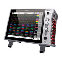
Hioki Memory HiCorder MR6000-01 Instruction Manual (392 pages)
Brand:
Hioki
| Category:
Measuring Instruments
| Size: 20 MB
Table of Contents
Table of Contents
3
Introduction
7
How to Use this Document
8
Measurement Method
9
Measurement Procedure
9
Setting Measurement Conditions
11
Sampling Rate Setting Guideline
13
Using the Envelope
15
Configuring the Input Channel Settings
17
Analog Channels
19
Logic Channels
23
Configuring the Sheet Settings
25
Switching Sheets on the Waveform Screen
30
Generating XY Composite Waveforms
31
Starting/Stopping a Measurement
34
Operating the Waveform Screen and Analyzing Data
35
Reading Measured Values (Trace Cursors, Horizontal Cursors)
36
Specifying the Waveform Range (Section Cursor)
40
Changing the Display Magnification of the Waveforms While Moving the Section Cursor
41
Displaying Vertical Scales (Gauge Function)
42
Scrolling through Waveforms
44
Checking a Position of Waveforms with the Scroll Bar
45
Changing the Display Position and Display Magnification of Waveforms
46
Differentiating a Waveform Display Position and Display Magnification from those of Other Analog Channels
47
Operating the Rotary Knobs
50
Enlarging a Part of the Waveform (Zoom Function)
51
Generating XY Composite Waveforms (XY Composite)
52
Displaying Measured Values
54
Advanced Functions
57
Overlaying New Waveforms with Previously Acquired Waveforms
58
Converting Input Values (Scaling Function)
60
When Using Model U8969 Strain Unit
65
Adjusting the Waveform Display Positions (Variable Function)
66
Fine-Adjusting Input Values (Vernier Function)
68
Inverting a Waveform (Invert Function)
69
Copying Settings (Copy Function)
70
Configuring Module-Specific Settings
71
Configuring Model 8968 High Resolution Unit Settings
71
Configuring Model 8967 Temp Unit Settings
72
Configuring Model U8969 Strain Unit Settings
74
Configuring Model 8970 Freq Unit Settings
76
Configuring Model 8971 Current Unit Settings
79
Configuring Model 8972 DC/RMS Unit Settings
81
Configuring Model MR8990 Digital Voltmeter Unit Settings
82
Configuring Model U8974 High Voltage Unit Settings
84
Configuring Model U8977 3CH Current Unit Settings
85
Configure Model U8979 Charge Unit Settings
87
Generating Signals from Model U8793 Arbitrary Waveform Generator Unit
90
Configuring Model U8793 Arbitrary Waveform Generator Unit
92
Registering Arbitrary Waveforms in the U8793 Arbitrary Waveform Generator Unit
95
Editing Programs of the U8793 Arbitrary Waveform Generator Unit
100
Saving/Loading Data and Managing Files
103
Data that Can be Saved and Loaded
104
Saving Data
106
Saving Types and Setting Procedure
106
Structure of the Save Destination Folders
107
Automatically Saving Waveform Data
108
Real-Time Saving
112
Freely Choosing Data Items to be Saved and Save Files (SAVE Key)
115
Loading Data
119
Data Loading Procedure
119
Loading Waveform Data in a Batch
121
Automatically Loading the Settings (Automatic Setup Function)
121
Managing Files
122
Configuring the Trigger Settings
123
Trigger Setting Procedure
124
Enabling the Trigger Function
125
Configuring the Trigger Timing Setting
126
Configuring the Pre-Trigger and Post-Trigger Settings
128
To Observe an Input Waveform While the Instrument Is Waiting for a Trigger
132
Setting the Trigger Satisfaction Conditions (AND/OR Operation) Among Trigger Sources
133
Triggering the Instrument Using Analog Signals (Analog Trigger)
135
Triggering the Instrument Using Logic Signals (Logic Trigger)
144
Triggering the Instrument at Regular Intervals (Interval Trigger)
146
Externally Triggering the Instrument (External Trigger)
148
Manually Triggering the Instrument (Forcible Trigger)
148
Triggering the Instrument Using CAN Signals (CAN Trigger)
149
Search Function
153
Searching for Peak Values
154
Searching for Positions Where a Trigger Condition Is Satisfied
157
Searching for Differences from a Fundamental Wave (Memory Hiconcierge)
162
Jumping to the Specified Position
165
Numerical Calculation Function
167
Numerical Calculation Procedure
168
Configuring the Numerical Calculation Settings
170
Displaying Numerical Calculation Results
181
Evaluating Calculation Results on a Pass/Fail Basis
183
Displaying Evaluation Results and Externally Outputting Signals
186
Numerical Calculation Types and Descriptions
187
Waveform Calculation Function
195
Waveform Calculation Procedure
196
Configuring the Waveform Calculation Settings
198
Defining Constants
205
Operators of the Waveform Calculation and Calculation Results
207
Examples of Configuring Waveform Calculation Settings
215
Obtaining an RMS Waveform from an Instantaneous Waveform
215
FIR Filter
218
IIR Filter
222
Explanations of Filter Calculation
227
Filter Type
227
Filter Configuration
228
FFT Calculation Function
229
Operating Procedure
230
Enabling the FFT Calculation Settings
232
Setting FFT Calculation Conditions
234
Specifying the Number of Calculation Points
234
Configuring the Window Function Settings
237
Configuring the Calculation Result Peak Value Settings
239
Averaging Calculation Results
240
FFT Calculation Advanced Settings
244
Performing Calculations on the Waveform Screen
248
To Specify a Range before Calculation
248
FFT Calculation Types
251
Calculation Types and Display Examples
251
Calculation Types and Internal Calculation Formulas
260
Memory Division Function
261
Configuring the Memory Division Settings
262
Configuring the Display Settings
263
Dual Sampling
267
Dual Sampling Procedure
268
Configuring Dual Sampling Settings
269
Operating the Waveform Screen for Analyzing Waveforms
273
Calculation Function
278
Files
280
Automatically Saving Waveform Data
281
Freely Choosing Data Items to be Saved and Save Files (SAVE Key)
282
Loading Waveform Data
282
CAN/LIN Measurement Function
283
CAN/LIN Measurement Procedure
284
Connecting CAN/LIN Interfaces
286
Configuring the CAN/LIN Interface Settings
291
Configuring the CAN/LIN Definition Data Settings
297
Choosing CAN Definition Data
303
Configuring the Transmission Function Settings (Creating a Transmission List)
305
Choosing Data Sets to be Displayed as Waveforms (When Displaying Waveforms During Measurement)
310
Choosing Data to be Displayed as Waveforms (When Using the Waveform Calculation Function)
311
Saving Data
314
Configuring the System Environment Settings
315
Connecting the Instrument to Computers
321
Configuring the LAN Settings and Connecting the Instrument to the Network
323
Configuring the LAN Settings with the Instrument
323
Managing Data in the Instrument with the FTP Server Function
328
Configuring the FTP Sever Setting with the Instrument
329
Operating the Instrument with Your Computer (FTP Server Function)
330
Sending Data to a Computer with the FTP Client Function
331
Configuring an FTP Server Setting on a Computer
332
Configuring the FTP Client Setting with the Instrument
337
Operating the Instrument with a Browser Installed in a Computer
339
Connecting Your Computer to the Instrument with a Web Browser
340
Remotely Operating the Instrument
341
Starting/Stopping Measurement
342
Configuring the Comment Setting
343
Acquiring Data from the Instrument
344
Setting the Clock
345
Handling Files
345
Sending Email Messages
346
Configuring the Basic Setting for Sending Email Messages
347
Configuring the Email Contents Settings
348
Configuring the Authentication, Compression, and Encryption Settings for Email Messages to be Sent
349
Controlling the Instrument with Command Communications (LAN)
351
Externally Controlling the Instrument
353
External Input and Output
354
External Input (IN1), (IN2)
354
External Output (OUT1), (OUT2)
355
Trigger Output (TRIG.OUT)
357
External Trigger Terminal (EXT.TRIG)
359
External Sampling (EXT.SMPL)
362
Appendix
363
Information for Reference Purposes
363
Waveform File Size (Values for Reference Purposes)
363
Maximum Recordable Time When the Real-Time Saving Is Enabled (Values for Reference Purposes)
367
Scaling Method for Strain Gauges
373
Example of a Waveform Text File
375
File Saving Rates (Values for Reference Purposes)
376
FFT Definitions
377
Dual Sampling
386
Index
387
Advertisement
Hioki Memory HiCorder MR6000-01 Instruction Manual (291 pages)
MEMORY HiCORDER
Brand:
Hioki
| Category:
Voice Recorder
| Size: 14 MB
Table of Contents
Table of Contents
2
Introduction
5
How to Refer to this Document
6
1 Measurement Method
7
Measurement Procedure
8
Setting Measurement Conditions
9
Sampling Rate Setting Guideline
9
Using the Envelope
13
Configuring the Input Channel Settings
15
Analog Channels
17
Configuring the Sheet Settings
20
Logic Channels
21
Switching Sheets on the Waveform Screen
22
Starting/Stopping a Measurement
25
2 Operating the Waveform Screen and Analyzing Data
26
Reading Measured Values (Trace Cursors)
26
Specifying the Waveform Range (Section Cursor)
31
Changing the Display Magnification of the Waveforms While Moving the Section Cursor
32
Displaying Vertical Scales (Gauge Function)
33
Scrolling through Waveforms
34
Scrolling through Waveforms
35
Checking a Position of Waveforms with the Scroll Bar
36
Changing the Display Position and Display Magnification of Waveforms
37
Differentiating a Waveform Display Position and Display Magnification from those of Other Analog Channels
37
Position and Display Magnification from those of Other Analog Channels
38
Operating the Rotary Knobs
41
Enlarging a Part of the Waveform (Zoom Function)
42
3 Advanced Functions
43
Overlaying New Waveforms with Previously Acquired Waveforms
44
Converting Input Values (Scaling Function)
46
When Using Model U8969 Strain Unit
51
Fine-Adjusting Input Values (Vernier Function)
52
Inverting a Waveform (Invert Function)
53
Copying Settings (Copy Function)
54
Configuring Module-Specific Settings
55
Configuring Model 8968 High Resolution Unit Settings
55
Configuring Model 8967 Temp Unit Settings
56
Configuring Model U8969 Strain Unit Settings
58
Configuring Model 8970 Freq Unit Settings
60
Configuring Model 8971 Current Unit Settings
63
Configuring Model 8972 DC/RMS Unit Settings
64
Configuring Model MR8990 Digital Voltmeter Unit Settings
65
Settings 58
66
Configuring Model U8974 High Voltage Unit Settings
67
Configuring Model U8977 3CH Current Unit Settings
68
Configure Model U8979 Charge Unit Settings
70
4 Saving/Loading Data and Managing Files
73
Data that Can be Saved and Loaded
74
Saving Data
75
Saving Types and Setting Procedure
75
Automatically Saving Waveform Data
76
Real-Time Save
80
Freely Choosing Data Items to be Saved and Save Files (SAVE Key)
82
Loading Data
85
Data Loading Procedure
85
Loading Waveform Data in a Batch
87
Automatically Loading the Settings (Auto-Setup Function)
87
Managing Files
88
5 Configuring the Trigger Settings
89
Trigger Setting Procedure
90
Enabling the Trigger Function
91
Configuring the Trigger Timing Setting
92
Configuring the Pre-Trigger and Post-Trigger Settings
94
To Observe an Input Waveform While the Instrument Is Waiting for a Trigger
98
Setting the Trigger Satisfaction Conditions (AND/OR Operation) Among Trigger Sources
99
Triggering the Instrument Using Analog Signals (Analog Trigger)
101
Triggering the Instrument with Logic Signals (Logic Trigger)
110
Triggering the Instrument at Regular Intervals (Interval Trigger)
112
Externally Triggering the Instrument (External Trigger)
114
Manually Triggering the Instrument (Forcible Trigger)
114
6 Search Function
115
Searching for Peak Values
116
Searching for Positions Where a Trigger Condition Is Satisfied
118
Searching for Differences from a Fundamental Wave (Memory Hiconcierge)
122
Jump to the Specified Position
124
7 Numerical Calculation Function
127
Numerical Calculation Procedure
128
Configuring the Numerical Calculation Settings
130
Displaying Numerical Calculation Results
141
Evaluating Calculation Results on a Pass/Fail Basis
142
Displaying Evaluation Results and Externally Outputting Signals
145
Numerical Calculation Types and Descriptions
146
8 Waveform Calculation Function
153
Waveform Calculation Procedure
154
Configuring the Waveform Calculation Settings
156
Defining Constants
162
Operators of the Waveform Calculation and Calculation Results
164
Examples of Configuring Waveform Calculation Settings
169
Obtaining an RMS Waveform from an Instantaneous Waveform
169
FIR Filter
172
IIR Filter
177
Explanations of Filter Calculation
182
Filter Type
182
Filter Configuration
183
9 FFT Calculation Function
185
Operating Procedure
186
Enabling the FFT Calculation Settings
188
Setting FFT Calculation Conditions
190
Specifying the Number of Calculation Points
190
Configuring the Window Function Settings
193
Configuring the Calculation Result Peak Value Settings
195
Averaging Calculation Results
196
FFT Calculation Advanced Settings
200
Making Calculations on the Waveform Screen
203
To Specify a Range before Calculation
203
FFT Calculation Types
206
Calculation Types and Display Examples
206
Calculation Types and Internal Calculation Formulas
214
10 Memory Division Function
215
Configuring the Memory Division Settings
216
Configuring the Display Settings
217
11 Configuring the System Environment Settings
221
Environment Settings
221
12 Connecting the
227
Computers
227
Configuring the LAN Settings and Connecting the Instrument to the Network
229
Configuring the LAN Settings with the Instrument
229
Instrument to Computers
229
Managing Data in the Instrument with the FTP Server Function
234
Configuring the FTP Sever Setting with the Instrument
235
Operating the Instrument with Your Computer (FTP Server Function)
236
Sending Data to a Computer with the FTP Client Function
237
Configuring an FTP Server Setting on a Computer
238
Configuring the FTP Client Setting with the Instrument
243
Operating the Instrument with a Browser Installed in a Computer
244
Connecting Your Computer to the Instrument with a Web Browser
245
Remotely Operating the Instrument
246
Starting/Stopping Measurement
247
Configuring the Comment Setting
248
Acquiring Data from the Instrument
249
Setting the Clock
250
Handling Files
250
Sending Email Messages
251
Configuring the Basic Setting for Sending Email Messages
252
Configuring the Email Contents Settings
253
Configuring the Authentication, Compression, and Encryption Settings for Email Messages to be Sent
254
Controlling the Instrument with Command Communications (LAN)
256
13 Externally Controlling the Instrument
259
External Input and Output
260
External Input (IN1), (IN2)
260
External Output (OUT1), (OUT2)
261
Trigger Output (TRIG.OUT)
263
External Trigger Terminal (EXT.TRIG)
265
External Sampling (EXT.SMPL)
267
Appendix
269
Information for Reference Purposes
269
Waveform File Size (Values for Reference Purposes)
269
Maximum Recordable Time When the Real-Time Save Is Enabled (Values for Reference Purposes)
273
Scaling Method for Strain Gauges
279
Example of a Waveform Text File
281
FFT Definitions
282
Hioki Memory HiCorder MR6000-01 Instruction Manual (210 pages)
Brand:
Hioki
| Category:
Measuring Instruments
| Size: 8 MB
Table of Contents
Table of Contents
3
Introduction
5
How To Refer To This Manual
6
1 Measurement Method
7
Measurement Procedure
7
Configuring Measurement Conditions
9
X84; Sampling Rate Setting Guideline
11
X84; Using the Envelope
13
Setting Input Channels
15
X84; Analog Channels
17
X84; Logic Channels
21
Setting the Sheets
22
X84; Switching Sheets on the Waveform Screen
23
Starting/Stopping the Measurement
24
2 Operating the Waveform Screen and Analyzing Data
25
Reading Measured Values (Trace Cursors)
26
Specifying the Waveform Range (Section Cursor)
30
X84; Changing the Display Magnification of the Waveforms While Moving the Section Cursor
31
Displaying Vertical Scales (Gauge Function)
32
Scrolling Waveforms
34
X84; Scrolling Waveforms
34
The Scroll Bar
35
Changing the Display Position and Display Magnification of the Waveforms
36
X84; Differentiating the Waveform Display Position and Display Magnification for each Analog Channel
37
Operating the Rotary Knob
40
Enlarging a Part of the Waveform (Zoom Function)
41
3 Advanced Functions
43
Overlaying New Waveforms with Previously Acquired Waveforms
44
Converting Input Values (Scaling Function)
46
X84; When Using Model U8969 Strain Unit
51
Fine-Adjusting Input Values (Vernier Function)
52
Inverting the Waveform (Invert Function)
53
Copying Settings (Copy Function)
54
Configuring Module-Specific Settings
55
X84; Setting Model 8968 High Resolution Unit
55
X84; Setting Model 8967 Temp Unit
56
X84; Setting Model U8969 Strain Unit
58
X84; Setting Model 8970 Freq Unit
60
X84; Setting Model 8971 Current Unit
63
X84; Setting Model 8972 DC/RMS Unit
65
X84; Setting Model MR8990 Digital Voltmeter Unit
66
X84; Setting Model U8974 High Voltage Unit
68
4 Saving/Loading Data and Managing Files
69
Data that Can be Saved and Loaded
70
Saving Data
71
X84; Save Types and Setting Procedure
71
X84; Saving Waveform Data Automatically
72
X84; Real-Time Save
76
X84; Freely Selecting Data Items to be Saved and Save Files (SAVE Key)
78
Loading Data
81
X84; Data Loading Procedure
81
X84; Loading the Settings Automatically (Auto-Setup Function)
82
Managing Files
83
5 Setting the Trigger
85
Trigger Setting Procedure
86
Enabling the Trigger Function
87
Setting the Trigger Timing
88
Setting the Pre-Trigger and Post-Trigger
90
X84; to Observe the Input Waveforms While the Instrument Is Waiting for a Trigger
94
Setting the Trigger Logical Conditions (AND/OR) Among Trigger Sources
95
Triggering the Instrument Using Analog Signals
97
Triggering the Instrument with Logic Signals (Logic Trigger)
106
Triggering the Instrument at Regular Intervals (Interval Trigger)
108
Triggering the Instrument Externally (External Trigger)
110
Triggering the Instrument Manually (Forcible Trigger)
110
6 Search Function
111
Searching for Peak Values
112
Searching for the Positions Where Trigger Condition Is Satisfied
114
Searching for Differences from the Fundamental Wave (Memory Hiconcierge)
118
Allowing the Display to Jump to the Specified Position
120
7 Numerical Calculation
123
Function
123
Numerical Calculation Procedure
124
Setting Numerical Calculation
126
X84; Displaying the Numerical Calculation Results
135
Evaluating the Calculation Results on a Pass/Fail Basis
136
X84; Displaying the Evaluation Results and Outputting Signals Externally
139
Numerical Calculation Types and Descriptions
140
8 Setting the System Environment
147
9 Connecting the Instrument to Pcs
153
Configuring the LAN Settings and Connecting to the Network
154
X84; Configuring the LAN Settings with the Instrument
154
And Connecting to the Network
155
Managing Data in the Instrument with the FTP Server Function
159
X84; Setting the FTP Sever with the Instrument
160
X84; Operating the Instrument with a PC (FTP Server Function)
161
Sending Data to a PC with the FTP Client Function
162
X84; Setting up an FTP Server on a PC
163
X84; Setting the FTP Client with the Instrument
167
Operating the Instrument with a Browser Installed in a PC
168
X84; Connecting the PC to the Instrument with Internet Browser
169
X84; Operating the Instrument Remotely
170
X84; Starting/Stopping the Instrument
171
X84; Setting the Comment
172
X84; Acquiring Data from the Instrument
173
X84; Setting the Clock
174
X84; Handling Files
174
Sending Emails
175
X84; Configuring the Basic Setting for Sending Email
176
X84; Setting Email Contents
177
X84; Setting Authentication, Compression, and Encryption for Emails to be Sent
178
Controlling the Instrument with Command Communications (LAN)
180
10 Controlling the Instrument Externally
183
External Input and Output
184
X84; External Input (IN1), (IN2)
184
X84; External Output (OUT1), (OUT2)
185
X84; Trigger Output (TRIG.OUT)
187
X84; External Trigger Terminal (EXT.TRIG)
189
External Sampling (EXT.SMPL)
191
11 Appendix
193
Information for Reference Purposes
193
X84; Waveform File Size (for Reference)
193
X84; Maximum Recording Time When the Real-Time Save Is on (Reference)
197
X84; Scaling Method for Strain Gauges
203
X84; Example of a Waveform Text File
204
Advertisement
Hioki Memory HiCorder MR6000-01 Quick Start Manual (160 pages)
MEMORY HiCORDER
Brand:
Hioki
| Category:
Recording Equipment
| Size: 10 MB
Table of Contents
Table of Contents
4
Introduction
6
Notations
7
Confirming Package Contents
9
Options (Sold Separately)
10
Safety Information
11
Operation Precautions
13
How to Refer to this Document
22
1 Overview
24
Product Overview and Features
24
Name and Function of each Part
25
Screen
29
Screen Configuration
29
Explanation of each Screen
30
Basic Operation
32
Touch Panel
32
Rotary Knob
33
Changing Screens and Settings
35
Quick-Access Menu
37
Key Lock
38
Help Function (Displaying Manuals)
38
Mouse Operation
39
Touch Keyboard
39
2 Preparing for Measurement
42
Installing and Removing Modules
43
Allocation of Modules and Channels
44
Attaching Connection Cords
45
Connection Cords (for Measuring Voltage, Frequency, or Rotation Speed, and Obtaining Accumulations)
46
Thermocouple (Temperature)
48
Strain Gauge Transducer
49
Current Sensor
51
Acceleration Sensor
54
Logic Probe (Measuring Logic Signals)
56
Connection Cable (for Precisely Measuring Voltage)
56
Connection Cable (for Measuring High Voltage)
57
Supplying Power to Current Sensors
58
External Sampling (EXT.SMPL)
59
Connecting the External Control Terminals
60
Connecting the Instrument with Computers
62
Preparing Storage Devices (Recording Media)
64
SD Memory Card
64
USB Flash Drive
64
Built-In Drive
65
Removing Storage Devices
65
Formatting Storage Devices
66
How to Open the Media Box
67
Supplying Power to the Instrument
68
Turning on the Instrument
68
GND Terminal (Functional Earth Terminal)
68
Turning off the Instrument
68
Setting the Clock
69
Executing Zero-Adjustment
70
Executing Calibration
72
MR8990 Installed)
72
3 Measurement Method
74
Inspection before Measurement
74
Setting Measurement Conditions
75
Sampling Rate Setting Guideline
76
Configuring the Input Channel Settings
77
Analog Channel
78
Configuring the Level Trigger Settings
80
Starting/Stopping a Measurement
82
Saving Data Consisting of Items Selected
83
Save Types and Setting Procedure
83
Selective Save
84
Measuring Signals with the Auto-Range Setting
86
4 Analysis Method
88
Reading Measured Values (Trace Cursors)
88
Handling Waveforms
91
Scrolling through Waveforms
91
Zooming in and out Waveforms
91
Loading Data on Your Computer (Wave Viewer)
92
5 Specifications
94
Specifications of Model MR6000
94
General Specifications
94
Trigger
98
Waveform Screen
100
Setting Screen
101
File
104
Calculation
105
Memory Division
108
Waveform Search
108
Specifications of the Options
110
Model Z5021 Probe Power Unit
110
Model U8332 SSD Unit
110
Model U8333 HD Unit
111
Model 8966 Analog Unit
111
Model 8967 Temp Unit
113
Model 8968 High Resolution Unit
115
Model U8969 Strain Unit
117
Model 8970 Freq Unit
119
Model 8971 Current Unit
121
Model 8972 DC/RMS Unit
123
Model 8973 Logic Unit
125
Model MR8990 Digital Voltmeter Unit
125
Model U8974 High Voltage Unit
127
Model U8975 4Ch Analog Unit
129
Model U8976 High Speed Analog Unit
131
Model U8977 3CH Current Unit (Available for the Firmware Version 2.10 or Later)
133
Model U8978 4CH Analog Unit (Available for the Firmware Version 2.10 or Later)
135
Model U8979 Charge Unit (Available for the Firmware Version 2.10 or Later)
137
6 Maintenance and Service
140
Troubleshooting
142
Before Sending the Instrument for Repair
142
Initializing the Instrument
144
Message
145
Error Messages
146
Warning Messages
147
Self-Check
151
Memory Check
151
Touch Panel Check
152
Key Check
152
LCD Check
152
LAN Check
153
Media Check
154
System Configuration Check
155
Cleaning the Instrument
155
Disposing of the Instrument (Removing the Lithium Battery)
156
Hioki Memory HiCorder MR6000-01 Quick Start Manual (142 pages)
memory hicorder
Brand:
Hioki
| Category:
Recording Equipment
| Size: 8 MB
Table of Contents
Table of Contents
1
Introduction
7
Notation
8
Verifying Package Contents
10
X84; Options (Sold Separately)
11
Safety Information
12
Operation Precautions
14
How to Refer to this Document
22
Overview
23
Product Overview And Features
23
Part Names and Functions
24
Part Names And Functions
24
Screen
28
X84; Screen Configuration
28
X84; Explanation for Screen Contents
29
Basic Operation
31
X84; Touch Panel
31
X84; Rotary Knob
32
X84; Changing Screens and Settings
33
X84; Key Lock
35
X84; Help (Displaying Manuals)
35
X84; Key Operations with Mouse
36
X84; Touch Keyboard
36
Preparing for Measurement
37
Installing and Removing Modules
38
X84; Allocation of Modules and Channels
39
Attaching Connection Cables
40
Rotation Speed, Count)
41
X84; Thermocouple (Temperature)
43
X84; Strain Gauge Transducer
44
X84; Current Sensor
46
X84; Logic Probe (Logic Signal)
47
X84; Connection Cable (High Precision Voltage)
47
X84; Connection Cable (High Voltage)
48
Supplying Power to Current Sensors
49
External Sampling (EXT.SMPL)
50
Connecting the External Control Terminals
51
Connecting the Instrument with Pcs
53
Preparing Storage Devices (Recording Media)
54
X84; SD Memory Card
54
X84; USB Flash Drive
54
X84; Built-In Drive
55
X84; Removing Storage Devices
55
X84; Formatting Storage Devices
56
Opening The Media Box
57
Supplying Power to the Instrument
58
X84; Turning on the Instrument
58
X84; GND Terminal (Functional Earth Terminal)
58
X84; Turning off the Instrument
58
Setting the Clock
59
Regulating the Zero Position (Zero Adjustment)
60
Executing the Calibration (When Model MR8990 Is Installed)
62
Measurement Method
63
Inspection before Measurement
63
Setting Measurement Conditions
64
X84; Sampling Rate Setting Guideline
65
Configuring the Input Channel Setting
66
X84; Analog Channel
67
Setting the Level Trigger
69
Starting/Stopping the Measurement
71
Saving Data Consisting of Selected Items
72
Measurement with the Auto-Range Setting
74
Analysis Method
77
Reading Measured Values (Trace Cursors)
77
Handling Waveforms
80
X84; Scrolling Waveforms
80
X84; Zooming in and out Waveforms
80
Loading Data with PC (Wave Viewer)
81
Specifications
83
Instrument Specifications
83
X84; General Specifications
83
X84; Trigger
87
X84; Waveform Screen
89
X84; Setting Screen
90
X84; File
92
X84; Calculation
93
X84; Waveform Search
94
X84; Others
94
Specifications For Options
96
X84; Model Z5021 Probe Power Unit
96
X84; Model U8332 SSD Unit
96
X84; Model U8333 HD Unit
97
X84; Model 8966 Analog Unit
97
X84; Model 8967 Temp Unit
99
X84; Model 8968 High Resolution Unit
101
X84; Model U8969 Strain Unit
103
X84; Model 8970 Freq Unit
105
X84; Model 8971 Current Unit
107
X84; Model 8972 DC/RMS Unit
109
X84; Model 8973 Logic Unit
110
X84; Model MR8990 Digital Voltmeter Unit
111
X84; Model U8974 High Voltage Unit
113
X84; Model U8975 4Ch Analog Unit
115
X84; Model U8976 High Speed Analog Unit
117
Maintenance and Service
119
Trouble Shooting
121
X84; before Having the Instrument Repaired
121
Initializing the Instrument
123
Message
124
X84; Error Messages
125
X84; Warning Messages
125
Self-Test
129
X84; Memory Check
129
X84; Touch Panel Check
130
X84; KEY Check
130
X84; LCD Check
130
X84; LAN Check
131
X84; Media Check
132
X84; System Configuration Check
133
Cleaning the Instrument
134
Disposing of the Instrument (Removing the Lithium Battery)
134
Advertisement
Related Products
Hioki Memory HiCorder MR6000
Hioki MR8880-20
Hioki MR8847-53
Hioki MR8827
Hioki MR8790
Hioki MR8791
Hioki MR8740-50
Hioki MR8741
Hioki MEMORY HiCORDER MR8847-03
Hioki MR8875
Hioki Categories
Measuring Instruments
Test Equipment
Data Loggers
Multimeter
Accessories
More Hioki Manuals
Login
Sign In
OR
Sign in with Facebook
Sign in with Google
Upload manual
Upload from disk
Upload from URL