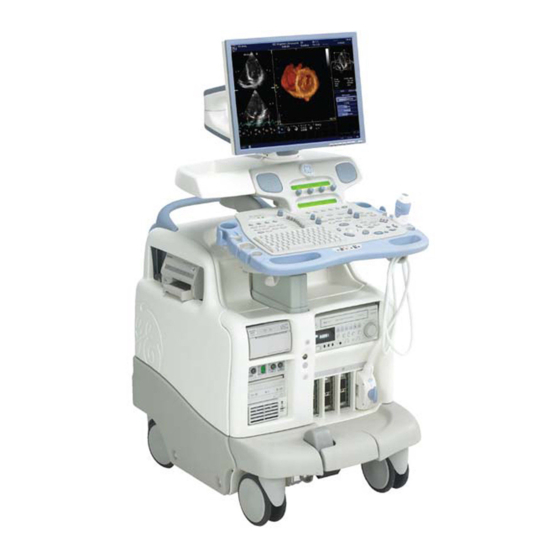
Sign In
Upload
Manuals
Brands
GE Manuals
Medical Equipment
Vivid 7
GE Vivid 7 Manuals
Manuals and User Guides for GE Vivid 7. We have
2
GE Vivid 7 manuals available for free PDF download: Service Manual
GE Vivid 7 Service Manual (858 pages)
Brand:
GE
| Category:
Medical Equipment
| Size: 31.59 MB
Table of Contents
Table of Contents
13
Overview
39
Purpose of Chapter 1
39
Contents in Chapter 1
39
Purpose of Service Manual
39
Product Description
44
Important Conventions
47
Conventions Used in Book
47
Standard Hazard Icons
48
Product Icons
49
Safety Considerations
53
Overview
53
Introduction
53
Human Safety
54
Mechanical Safety
55
Electrical Safety
57
Labels Locations
58
Labels on Front of Monitor and Operator Panel
58
Labels on Rear of LCD Monitor
60
Labels on Front Handle
61
Labels Near Connectors on Front
62
Label on External I/O
63
Labels at AC Mains Inlet and Circuit Breaker
64
Label on Rear Cover - VIVID 7 Dimension
66
Label on Rear Cover - VIVID 7
67
Label on Rear Cover - VIVID 7 PRO
70
Label on Rear Cover - VIVID 7 Dimension for China
72
Label on Rear Cover - VIVID 7 for China
76
Label on Rear Cover - VIVID 7 PRO for China
77
Label on Rear Cover - VIVID 7 Dimension for Korea
81
Label on Rear Cover - VIVID 7 PRO for Korea
82
Label on Rear Cover - VIVID 7 - Details Descriptions
83
Labels on Internal I/O (Inside Scanner)
85
Label, Internal Connections (Int.conn.)
89
Label, Internal Connections (Int.conn.)
90
Label, BEP1, Internal Connections (Int.conn.)
91
Label, BEP2, Internal Connections (Int.conn.)
92
Label, BEP4 as BEP2 Replacement, Internal Connections (Int.conn.)
93
Label, BEP2.2, Internal Connections (Int.conn.)
94
Label, BEP4 as BEP2.2 Replacement, Internal Connections (Int.conn.)
95
Label, Bep3.X, Internal Connections (Int.conn.)
96
Label, Bep3.X with 4D, Internal Connections (Int.conn.)
97
Label, Bep4.X, Internal Connections (Int.conn.)
98
Label, Bep4.X with 4D, Internal Connections (Int.conn.)
99
Label, Disassembly Nester, Part 1 (Left Part of Label)
100
Label, Disassembly Nester, Part 2 (Right Part of Label)
103
Dangerous Procedure Warnings
106
Lockout/Tagout (LOTO) Requirements
107
Returning/Shipping Probes and Repair Parts
107
Electromagnetic Compatibility (EMC)
108
What Is EMC
108
Compliance
108
Electrostatic Discharge (ESD) Prevention
108
Customer Assistance
109
Contact Information
109
System Manufacturer
110
Overview
111
Purpose of Chapter 2
111
Contents in Chapter 2
111
General Console Requirements
112
Console Environmental Requirements
112
Electrical Requirements
113
EMI Limitations
117
Probes Environmental Requirements
119
Time and Manpower Requirements
119
Facility Needs
120
Purchaser Responsibilities
120
Required Facility Needs
121
Desirable Features
122
Minimal Floor Plan Suggestion
122
Networking Setup Requirements
123
Purpose of Chapter 3
125
Contents in Chapter 3
125
Installation Reminders
126
Average Installation Time
126
Installation Warnings
126
Receiving and Unpacking the Equipment
128
Overview
128
The Post Delivery Checklist
129
The Tilt & Shock Indicators
130
Unpacking VIVID 7
134
Packing Materials - Recycling Information
137
Preparing for Setup
138
Physical Inspection
138
EMI Protection
138
Completing the Setup
138
System Specifications
138
Electrical Specifications
139
Connections on the External IO
143
Connections on the Patient I/O Panel
144
Probe Connection
145
Power On/Bootup
147
Switching off the Unit
151
Configuration
152
VIVID 7 Configuration
152
Service Screen Setup
157
Optional Peripherals/Peripheral Connection
160
Available Probes
162
Video Specification
162
Software Options Configuration
163
Connectivity Overview
165
Physical Connection
165
Direction Fc091194, Revision
166
Connectivity Setup - Software V7.X (BT'08), V6.X, V5.X and V4.X
166
Introduction
166
Contents in this Section
166
Compatibility
167
Select TCP/IP Set-Up Screen
168
Changing the Computer Name, AE Title And/Or Port Number (Port No.)
169
Set the Scanner's Network Information - S/W V4.2/V5.2/V6.1/V7.X and Later
173
Set the Scanner's Network Information - S/W V4.0/V4.1/V5.0/V5.1/V6.0
174
Advanced Settings
175
DHCP Configuration
176
Set the Remote Archive's Network Information
179
Save the New Settings
179
Remote Path
180
Configurable Remote Path User
181
Set up Connection to a DICOM Server in a Network
182
Export Configuration
194
Create a New Dataflow
199
Mapping of Parameters from VIVID 7 to DICOM
209
Introduction
213
Contents in this Section
213
Set the Scanner's Network Information - Software Version V3.X
215
Set the Remote Archive's Network Information - Software Version V3.X
216
Save the New Settings
216
Connect to a DICOM Server in a Network - Software Version V3.X
217
HL7 Communication Setup - Software V3.X
222
Query/Retrieve (Q/R) Setup for Software V3.X
226
Introduction
233
Contents in this Section
233
Compatibility
233
Select TCP/IP Set-Up Screen - Software V2.X
235
Set the Scanner's Network Information - Software Version V2.X
236
Set the Remote Archive's Network Information - Software V2.X
237
Save the New Settings - Software V2.X
237
Verification of a Connection Set up to Echopac PC - Software V2.X
241
Irection Fc091194, Revision IVID Ervice Anual
241
HL7 Communication Setup for Software V2.X
246
Set up Connection to a DICOM Server in a Network - Software V2.X
250
Ethernet Switch / Hub
257
Local Network Connection to Echopac PC Workstation
258
Hospital Network Connection to Echopac PC Workstation
259
Installation Paperwork
260
User's Manual(S)
260
Product Locator Installation Card
261
Post Delivery Check List
262
Irection Fc091194, Revision IVID Ervice Anual
262
Functional Checks
265
Overview
265
Purpose of Chapter 4
265
Contents in Chapter 4
265
Special Equipment Required
265
General Procedures
266
Overview
266
Power ON/ Boot up
267
Power Shut down
271
Log on to the System as 'ADM
276
Using Removable Media
278
Labeling Removable Media
280
Formatting Removable Media - Software Version V3.X and above
281
Formatting Removable Media - Software Version V2.X
282
Verifying Removable Media
282
Archiving and Loading Presets - Software Version V2.X/V3.X
283
Space Management - Software Version V7.X/V6.X/V5.X/V4.X
285
Backup - Software Version V7.X/V6.X/V5.X/V4.X
288
Moving and Transporting the VIVID 7
291
Functional Checks
292
Overview
292
Contents in this Section
292
Preparation
292
Basic Controls
293
Performance Tests
295
Mode (B Mode) Checks
296
M Mode Checks
303
Color Mode Checks
307
Doppler Mode Checks
313
Volume Rendering Test
319
Tissue Velocity Imaging (TVI) Checks
321
Contrast Checks
327
Stress Echo
327
Measurements and Multi Image Checks
328
Multi Image Checks
330
Probe/Connectors Check
331
ECG Check
332
Cineloop Check
333
Back-End Processor Checks
337
Peripheral Checks
338
Mechanical Functions Checks
342
Application Turnover Check List
346
Software Configuration Checks
346
Power Supply
346
Power Supply Test Procedure
346
Site Log
346
Overview
347
General Information
348
Introduction
348
Signal Flow
349
System Configuration and Software
349
Operator Panel
349
The Electronics
349
Block Diagram - Units with Front-End Card Cage, Version 1 (FEP1)
350
Block Diagram - Units with Front-End Card Cage, Version 2 (FEP2)
351
Front-End Processor (FEP)
352
General Description
352
Fep1
352
Fep2
353
Fep's Location in the Unit
354
Input Signals
354
Bidirectional Signals
354
Output Signals
354
Fuses, Jumpers, Dip-Switches and Leds
354
Transmitter and Receiver Subsystem
355
Transmitter Board, TX128-5 (Version Introduced for BT'05)
360
Transmitter Board, TX128 (Version Used before BT'05)
365
Transducer Bus Boards, XD BUS
370
Relay Board (RLY)
372
Receiver Board, RX-128
377
Beam Former Board(S), BF-64
380
Front-End Controller Board, FEC
383
Digital Signal Processors Subsystem in Units with FEP1
391
RF & Tissue Processor Board, RFT
393
Spectrum Doppler Processor Board, SDP
398
Image Port (IMP) Board
402
Radio Frequency Interface Board, RFI
407
Motherboard (Backplane)
418
Back-End Processor (BEP)
419
BEP Overview
419
Irection Fc091194, Revision IVID Ervice Anual
419
Introduction
420
Signal Flow and Processing
420
Location of the Back-End Processor (BEP)
421
Back-End Processor (BEP) Block Diagrams
422
Back-End Processor (BEP) Descriptions
434
Internal Storage Devices
441
Back-End Processor (BEP) Inputs
441
Back-End Processor (BEP) Outputs
443
UPS Battery Description
444
Patient I/O (Physio)
446
Patient I/O General Description
446
Patient I/O Location in the Unit
447
Patient I/O - Inputs
448
Patient I/O - Outputs
448
Internal I/O
449
General Description
449
Internal I/O - Location in the Unit
452
Input Signals to Internal I/O
453
Output Signals from the Internal I/O
457
Leds on Internal I/O
458
Fuses
458
Jumpers and Dip-Switches
458
Top Console with Monitor and Operator Panel
459
General Description
459
Monitors
461
Operator Panel
462
External I/O
463
General Description, External I/O
463
Location in the Unit
464
Input Signals
465
Bi-Directional Signals
466
Output Signals
466
Reset Switch
467
Jumpers and Dip-Switches
467
Leds
467
Video Specifications
468
Peripherals
469
Internal Peripherals
469
External Peripherals
469
Modem (Option)
470
General Description
470
Location in the Unit
470
Modem (Option) Inputs/Outputs
471
Fuses
471
Jumpers and Dip-Switches
471
Leds on Modem
472
Power Distribution
473
Overall AC Power Distribution
473
AC Controller
475
DC Power
479
TX Power Supply
483
Mechanical Descriptions
487
General Description, Top Console on VIVID 7
487
Transporting VIVID 7
488
Location in the Unit
489
General Description, Top Console on VIVID 7 PRO
491
Location in the Unit VIVID 7 PRO
491
Air Flow Control
492
General Description
492
Location in the Unit
492
Software Overview
493
Introduction
493
System Software
493
Application Software
493
Software Patches
493
Service Platform
493
Connectivity Theory
494
Introduction
494
The Dataflow Concept
494
New Dataflows
495
Dataflow Examples
496
Sneaker Net" Environment
497
Direct Connection from VIVID 7 to an Echopac PC Workstation
497
Irection Fc091194, Revision IVID Ervice Anual
497
VIVID 7 and a DICOM Server in a Network
497
Product Manuals
497
Service Platform
498
Introduction
498
Ilinq Interactive Platform Features
498
Global Service User Interface (GSUI)
499
System Logs
500
Restart VIVID 7 after Diagnostics
500
LCD Monitor Adjustments
502
Overview
502
Cautions and Warnings
502
Access to Adjustments
502
Degaussing the CRT Monitor
503
Adjusting the Crt's Contrast and Brightness
504
Front-End Alignment Procedure (Beamformer Calibration)
506
Introduction
506
When to Use this Procedure
506
Front-End Alignment Procedure
507
Direction Lock and Brake Adjustment
509
Front Caster Brakes Adjustment Procedure
509
Direction Lock Adjustment Procedure
510
Rear Brakes Adjustment
512
Diagnostics/Troubleshooting
513
Overview
513
Purpose of this Chapter
513
Contents in this Chapter
513
Service Tools Overview
514
Service Software Tools
514
Special Service Tool
514
Frequently Asked Questions - FAQ
515
Error Message(S) During Start up
515
Service Safety Considerations
516
Gathering Troubleshooting Data
517
Overview
517
Collect Vital System Information
517
Collect a Trouble Image with Logs
518
Diagnostics Tools
519
Diagnostic Procedure Summary
519
Common Service Diagnostic Interface (GSUI)
520
Error Logs
523
Diagnostics Screen Overview
538
Image Quality
544
Calibration
545
Configuration
547
Utilities
548
Replacement
558
Home
559
Exit from Diagnostics
559
Common Diagnostics
560
Common Diagnostics - Utilities
561
PC (Back-End Processor) Diagnostics, Non-Interactive Tests
563
PC (Back-End Processor) Diagnostics, Interactive Tests
569
Acquisition Diagnostics
575
Acquisition Diagnostics Introduction
575
Calibration Screen
576
System Test
578
General Recommendations to Troubleshoot Noise Issues
586
EMI Prevention/Abatement
587
Replacement Procedures
589
Overview
589
Definitions of Left, Right, Front and Back
590
Returning/Shipping Probes and Repair Parts
591
Warnings
591
Side Covers (with Bumpers) Replacement Procedure
592
Manpower
592
Tools
592
Preparations
592
Side Covers Removal Procedure
592
Side Covers Installation Procedure
593
Verification - Functional Checks
593
Upper Rear Cover (Filter Cover) Replacement Procedure
594
Manpower
594
Tools
594
Upper Rear Cover Removal Procedure
594
Upper Rear Cover Installation Procedure
594
Verification - Functional Checks
594
Front Cover Replacement Procedure
595
Manpower
595
Tools
595
Preparations
595
Front Cover Removal Procedure
595
Front Cover Installation Procedure
595
Verification - Functional Checks
595
Air Filter Replacement Procedure
596
Manpower
596
Tools
596
Filter Removal Procedure
596
Filter Installation Procedure
596
Verification - Functional Checks
597
Lower Rear Cover Replacements Procedure
598
Manpower
598
Tools
598
Preparations
598
Lower Rear Cover Removal Procedure
598
Lower Rear Cover Installation Procedure
598
Verification - Functional Checks
599
Introduction
600
Preparations before Software Re-Installation
600
Customer Provided Prerequisite
601
Tools Provided with Unit or after an Upgrade
601
Preparations
602
Backup - Software Version V7.X/V6.X/V5.X/V4.X
606
Record SW Option Keys - Software Version V7.X/V6.X/V5.X/V4.X
621
Restore Patient Archive/System Config. - Software V7.X/V6.X/V5.X/V4.X
625
Verification - Functional Checks
625
Introduction
626
Preparations before Software Re-Installation
626
Verification - Functional Checks
641
Introduction
642
Prepare MO Disk for Patient Archive - Software Version V2.X
648
Backup of Patient Database & User Presets - Software Version V2.X
649
Record Standard Printer IP and Port Settings - Software Version V2.X
654
Restore Standard Printer IP and Port Settings - Software Version V2.X
666
Verification - Functional Checks
667
BEP Filter Assembly Replacement Procedure
668
Manpower
668
Tools
668
Preparations
668
BEP Filter Removel Procedure
668
BEP Filter Installation Procedure
668
Verification - Functional Checks
669
AC Power Replacement Procedure
670
Manpower
670
Tools
670
Preparations
670
AC Power Removal Procedure
671
AC Power Installation Procedure
672
Verification - Functional Checks
673
DC Power Replacement Procedure
674
Manpower
674
Tools
674
Preparations
674
DC Power Removal Procedure
675
DC Power Installation Procedure
676
Verification - Functional Checks
676
TX Power Replacement Procedure
677
Manpower
677
Tools
677
Preparations
677
TX Power Removal Procedure
678
TX Power Installation Procedure
678
Rear Casters Replacement Procedure
679
Manpower
679
Tools
679
Preparations
679
Rear Casters Removal Procedure
680
Rear Casters Installation Procedure
682
Front Casters Replacement Procedure
683
Manpower
683
Tools
683
Preparations
683
Front Casters Removal Procedure
684
Front Casters Installation Procedure
687
Front Bumper Replacement Procedure
688
Manpower
688
Tools
688
Preparations
688
Front Bumper Removal Procedure
688
Front Bumper Installation Procedure
688
Brake Pedal Replacement Procedure
689
Manpower
689
Tools
689
Direction Lock Pedal Replacement Procedure
690
Manpower
690
Tools
690
Direction Lock Replacement Procedure
690
Brake Pedal and Direction Lock Assembly Replacement Procedures
691
Manpower
691
Tools
691
Preparations
691
Brake Pedal and Direction Lock Removal Procedure
691
Brake Pedal and Direction Lock Installation Procedure
692
Verification - Functional Checks
692
Contents in Chapter 9
698
Definitions of Left, Right, Front and Back
698
List of Abbreviations
699
VIVID 7 Models and Hardware/Software Compatibility
703
Software
706
Software Version V5.X
708
Software Patches
712
Printer Drivers
712
Plastic Parts, Console, Top and Front
713
Plastic Parts, Airduct Cover and Cover Boxes
715
Plastic Parts, External Covers and Bumpers, Left, Right and Rear
716
Frogleg and Swivel Arm
717
Console Lock
718
Introduction
718
Console Lock - VIVID 7/VIVID 7 Dimension
719
Console Lock - VIVID 7 PRO
720
Gas Spring
721
Fan Assembly
722
Operator Panel
723
Introduction
723
Operator Panel-Version 3
723
Operator Panel-Version 1
723
Operator Panel-Common Parts
729
Monitor Assembly
730
LCD Monitor
730
CRT Monitor
731
Casters
732
Brake Assembly
733
Introduction
734
Front-End Processor Version 2 FRU Parts
736
Front-End Processor Version 1 FRU Parts
740
Back-End Processor
743
FRU Parts for Back-End Processor Version 4.3 (BEP4.3)
743
FRU Parts for Back-End Processor Version 4.2 (BEP4.2)
745
FRU Parts for BEP4 as Replacement for BEP2.0
749
FRU Parts for Back-End Processor Version 3.2 (BEP3.2)
751
FRU Parts for Back-End Processor Version 3.0 (BEP3.0)
753
FRU Parts for Back-End Processor Version 2.2 (BEP2.2)
754
FRU Parts for Back-End Processor Version 2 (BEP2)
755
FRU Parts for Back-End Processor Version 1 (BEP1)
756
AC Power Parts
757
Input /Output Modules
758
Peripherals
759
Peripherals Compatibility
759
Printers, Internal
761
Network Printers
762
Digital Video Disc Recorder (DVR)
763
Video Cassette Recorders (Vcrs)
763
USB Flash Card (USB Drive)
763
Footswitch
764
Modem Option
764
ECG Cables
774
Physio TX Parts
775
Probes
776
Supported Probes and Software Versions - BT'08
777
Supported Probes and Software Versions - BT'06
779
Supported Probes and Software Versions - BT'05
781
Supported Probes and Software Versions - BT'04
783
Probe Service Parts
786
Other Probe Part(S)
786
Options
787
Overview
787
Options - VIVID 7 Dimension/VIVID 7/VIVID 7 PRO - BT'04, Software V4.X
791
Options - VIVID 7/VIVID 7 PRO - BT'03, SW V3.X
794
Kits
795
Service Kits
795
VIVID 7 Upgrade Kits
796
Language Kits
798
Parts List for Bumper Kit, Frogleg
799
Parts Lists for Column Cover Kit
800
Accessory Boxes, VIVID 7 / VIVID 7 PRO
801
Accessory Box - Delivered with System
801
Accessory Box - SERVICE V7, US
803
Product Manuals
804
Overview
804
Care & Maintenance
819
Overview
819
Periodic Maintenance Inspections
819
Important Warnings
820
Why Do Maintenance
820
Keeping Records
820
Quality Assurance
820
Maintenance Task Schedule
821
How Often Should Maintenance Tasks be Performed
821
Tools Required
823
Special Tools, Supplies and Equipment
823
System Maintenance
824
Preliminary Checks
824
Input Power
826
Cleaning
827
Physical Inspection
828
Optional Diagnostic Checks
829
Probe Maintenance
829
Using a Phantom
830
Electrical Safety Tests
830
Safety Test Overview
830
GEHC Leakage Current Limits
831
Outlet Test - Wiring Arrangement - USA & Canada
832
Grounding Continuity
832
Chassis Leakage Current Test
834
Isolated Patient Lead (Source) Leakage-Lead to Ground
835
Isolated Patient Lead (Source) Leakage-Lead to Lead
836
Isolated Patient Lead (Sink) Leakage-Isolation Test
837
Probe Leakage Current Test
839
When There's too Much Leakage Current
842
Advertisement
GE Vivid 7 Service Manual (510 pages)
Brand:
GE
| Category:
Medical Equipment
| Size: 16.89 MB
Table of Contents
Table of Contents
9
Overview
25
Purpose of Chapter 1
25
Purpose of Service Manual
25
Typical Users of the Service Manual
26
VIVID 7 / VIVID 7 PRO Models Covered by this Manual
26
Purpose of Operator Manual(S)
31
Important Conventions
32
Conventions Used in Book
32
Standard Hazard Icons
33
Product Icons
34
Safety Considerations
36
Introduction
36
Human Safety
36
Mechanical Safety
36
Electrical Safety
37
Labels Locations
38
Dangerous Procedure Warnings
60
Lockout/Tagout Requirements (for USA Only)
60
EMC, EMI, and ESD
61
Electromagnetic Compatibility (EMC) and Interference (EMI)
61
CE Compliance
61
Electrostatic Discharge (ESD) Prevention
61
Customer Assistance
62
Contact Information
62
System Manufacture
63
Pre-Installation
65
Overview
65
Purpose of Chapter 2
65
General Console Requirements
66
Console Environmental Requirements
66
Electrical Requirements
67
EMI Limitations
68
Probes Environmental Requirements
70
Time and Manpower Requirements
70
Facility Needs
71
Purchaser Responsibilities
71
Required Facility Needs
72
Desirable Features
73
Minimal Floor Plan Suggestion
73
Networking Pre-Installation Requirements
74
Overview
77
Purpose of Chapter 3
77
Installation Reminders
77
Average Installation Time
77
Installation Warnings
78
Receiving and Unpacking the Equipment
79
Introduction
79
Receiving VIVID 7 / VIVID 7 PRO
80
Introduction
80
Unpacking VIVID 7 / VIVID 7 PRO
81
Transportation Box Dimensions
83
Preparing for Installation
84
Physical Inspection
84
EMI Protection
84
Completing the Installation
84
System Specifications
84
Electrical Specifications
85
Connect Footswitch
86
Connect Telephone Line to Modem Connector
86
Connect ECG
87
Connect Phono
87
Connect Pulse Pressure Transducer
88
Connect Ethernet
88
Probe Connection
89
Power On/Boot up
90
Power Shut down
93
Switching off the Unit
93
Configuration
97
VIVID 7 / VIVID 7 PRO Configuration
98
Service Screen
104
Optional Peripherals/Peripheral Connection
108
Available Probes
108
Video Specification
108
Software Options Configuration
109
Connectivity
111
Introduction
111
Physical Connection
111
Connectivity Setup
113
Installation Paperwork
132
User Manual(S)
132
Complete the Post Delivery Check List
133
Post Delivery Check List
134
Functional Checks
135
Overview
135
Purpose of Chapter 4
135
Special Equipment Required
135
General Procedures
136
Power ON/ Boot up
136
Power Shut down
139
Using Removable Media
143
Labeling Removable Media
144
Formatting Removable Media
145
Verifying Removable Media
145
Archiving and Loading Presets
146
Functional Checks
148
Preparation
148
Basic Controls
148
Performance Tests
150
2D Mode (B Mode) Checks
151
M Mode Checks
158
Color Mode Checks
162
Doppler Mode Checks
168
Tissue Velocity Imaging (TVI) Checks
174
Contrast Checks
180
Stress Echo
180
Measurements and Multi Image Checks
181
Multi Image Checks
183
Probe/Connectors Check
184
ECG Check
185
Cineloop Check
186
Backend Processor Checks
190
Peripheral Checks
191
Mechanical Functions Checks
195
Application Turnover Check List
197
Software Configuration Checks
197
Power Supply
198
Power Supply Test Procedure
198
Power Supply Adjustment
198
Components and Functions (Theory)
201
Overview
201
Purpose of Chapter 5
201
General Information
202
Block Diagram
203
Front End Processor
204
General Information
204
Front End Bus
204
Phased and Linear Array Front End
204
Transmitter Power Supply
205
MID Processors
205
Major Sub-Systems in VIVID 7 / VIVID 7 PRO
211
Front End Subsystem
212
MID Processors
213
Back End Processor
214
Introduction
214
Signal Flow and Processing
214
Location of the Back End Processor
214
BEP-1 Block Diagram
215
BEP-1 Description
216
BEP-2 Block Diagram
217
BEP-2 Description
218
PCVIC Card
219
UPS Battery Operation
219
Internal Storage Devices
220
Inputs
220
Outputs
222
Patient I/O (Physio)
223
Internal I/O
224
Location in the Unit
226
Leds
226
Fuses
226
Jumpers and Dip-Switches
226
Inputs
227
Outputs
229
Top Console
231
Peripherals
232
On-Board Peripherals
232
External Peripherals
232
Modem
233
Power Distribution
234
Overall AC Power Distribution
234
Overview
235
AC Power Distribution Box (PWB)
235
DC Power
237
TX Power Supply
241
Circuit Boards
244
Overview
244
Relay Board, RLY
245
Transmitter Board, TX128
247
Front End Controller Board, FEC-2
256
Transducer Bus Boards, XD BUS Boards
261
RF & Tissue Processor Board, RFT
262
Spectrum Doppler Processor Board, SDP
266
Image Port 2 Board, IMP2
270
Backend Processor
274
Patient I/O
278
Internal I/O
280
External I/O
287
Interconnect Cabling
290
Motherboard (Back Plane)
292
Modem
293
Video Specifications
295
Pal
295
Ntsc
295
System Logs
295
Board Rack Cooling System
296
General Description
296
Location in the Unit
296
Top Console Movement
297
Transportation of VIVID 7 / VIVID 7 PRO
297
Location in the Unit
298
General Description VIVID 7 PRO
300
Location in the Unit VIVID 7 PRO
300
Common Service Platform
301
Introduction
301
Ilinq Interactive Platform Features
301
Global Service User Interface (GSUI)
302
Overview
305
Purpose of Chapter 6
305
Power Supply Adjustments
305
Monitor Adjustments
306
Cautions and Warnings
306
Access to Adjustments
306
Adjustment Procedure(S)
306
Front End Alignment Procedure
307
When to Do a Front End Alignment Procedure
307
Procedure
307
Direction Lock and Brake Adjustment
308
Front Caster Brakes Adjustment Procedure
308
Direction Lock Adjustment Procedure
309
Rear Brakes Adjustment
311
Overview
313
Purpose of Chapter 7
313
Service Software Tools
313
Special Service Tool
313
Frequently Asked Questions
314
Diagnostics
315
Diagnostic Procedure Summary
315
Common Service Diagnostic Interface (Ultrasound Interface)
316
Service Home Page
317
Description of Screens
318
Error Logs
319
Utilities
329
Diagnostics
335
Image Quality
340
Calibration
341
Configuration
343
Utilities
344
Replacement
354
Home
355
Exit from Diagnostics
355
Common Diagnostics
356
Common Diagnostics - Utilities
357
PC (Backend Processor) Diagnostics, Non-Interactive Tests
359
PC (Backend Processor) Diagnostics, Interactive Tests
365
Acquisition Diagnostics
371
System Test Diagnostics Summary
371
Start System Test
371
Beamformer Calibration
372
System Test
373
Beamformer Calibration (Front End Alignment)
377
Troubleshooting
379
Console Troubleshooting Trees
379
Overview
383
Purpose of Chapter 8
383
Warnings
383
Plastic Parts Replacement Procedures
384
Overview of Covers and Bumpers
384
Side Covers Replacement Procedure
385
Front Cover Replacement Procedure
387
Filter Cover Replacement Procedure
388
Filter Replacement Procedure
389
Lower Rear Cover Replacements Procedure
390
SW Loading Procedure
391
Introduction
391
Customer Provided Prerequisite
391
Tools Provided with Unit or after a Software Upgrade
392
Preparation
393
Prepare MO Disks for Image Storage
394
Move Images
395
Prepare MO Disk for Patient Archive
398
Backup of Patient Database and User Presets
399
Recording of SW Option Keys, TCP/IP and Service Settings
400
Software Installation
406
Advertisement
Related Products
GE Vivid 7, Vivid E9
GE Vivid 7 PRO
GE Vivid i SafeLock Cart
GE Vivid 3
GE VividTE7
GE Vivid P3
GE Vivid in
GE Vivid iq
GE Vivid S6
GE Vivid q
GE Categories
Refrigerator
Ranges
Microwave Oven
Air Conditioner
Dishwasher
More GE Manuals
Login
Sign In
OR
Sign in with Facebook
Sign in with Google
Upload manual
Upload from disk
Upload from URL