
Related Manuals for GE Vivid 7


Summary of Contents for GE Vivid 7
- Page 1 GE Medical Systems Technical Publication Part Number FC091194 Revision 02 GE Medical Systems Vivid 7 / Vivid 7 PRO Service Manual Copyright© 2002 General Electric Co. All rights reserved...
- Page 3 VERSUCHEN SIE NICHT, DAS GERÄT ZU REPARIEREN, BEVOR WARNUNG DIESES KUNDENDIENST-HANDBUCH NICHT ZU RATE GEZOGEN UND VERSTANDEN WURDE. • WIRD DIESE WARNUNG NICHT BEACHTET, SO KANN ES ZU VERLETZUNGEN DES KUNDENDIENSTTECHNIKERS, DES BEDIENERS ODER DES PATIENTEN DURCH ELEKTRISCHE SCHLÄGE, MECHANISCHE ODER SONSTIGE GEFAHREN KOMMEN.
- Page 4 GE M EDICAL YSTEMS FC091194, R 7 / V 7 PRO S IRECTION EVISION IVID IVID ERVICE ANUAL • ESTE MANUAL DE SERVICIO SÓLO EXISTE EN INGLÉS. • SI ALGÚN PROVEEDOR DE SERVICIOS AJENO A GEMS SOLICITA UN IDIOMA QUE NO SEA EL INGLÉS, ES RESPONSABILIDAD DEL CLIENTE OFRECER UN SERVICIO DE TRADUCCIÓN.
- Page 5 All packages should be closely examined at time of delivery. If damage is apparent write “Damage In Shipment” on ALL copies of the freight or express bill BEFORE delivery is accepted or “signed for” by a GE representative or hospital receiving agent. Whether noted or concealed, damage MUST be reported to the carrier immediately upon discovery, or in any event, within 14 days after receipt, and the contents and containers held for inspection by the carrier.
- Page 6 Other connections between pieces of electrical equipment, calibrations and testing shall be performed by qualified GE Medical personnel. In performing all electrical work on these products, GE will use its own specially trained field engineers. All of GE’s electrical work on these products will comply with the requirements of the applicable electrical codes.
- Page 7 IVID ERVICE ANUAL Revision History REVISION DATE REASON FOR CHANGE Covers both Vivid 7 and Vivid 7 PRO 11. JUN. 2002 Replaces Vivid 7 Service Manual, Part Number FB091202 30. AUG. 2002 Updated per BT02-M4 release. Included description for BEP-2.
- Page 8 GE M EDICAL YSTEMS FC091194, R 7 / V 7 PRO S IRECTION EVISION IVID IVID ERVICE ANUAL List of Effected Pages Pages Revision Pages Revision Pages Revision Title Page 4-1 to 4-66 9-1 to 9-37 Warnings 5-1 to 5-104...
-
Page 9: Table Of Contents
Typical Users of the Service Manual ......1 - 2 Vivid 7 / Vivid 7 PRO Models Covered by this Manual ....1 - 2 Purpose of Operator Manual(s) . - Page 10 GE M EDICAL YSTEMS FC091194, R 7 / V 7 PRO S IRECTION EVISION IVID IVID ERVICE ANUAL CHAPTER 2 Pre-Installation Overview ............2 - 1 Purpose of Chapter 2 .
- Page 11 Vivid 7 / Vivid 7 PRO Configuration ......3 - 22...
- Page 12 GE M EDICAL YSTEMS FC091194, R 7 / V 7 PRO S IRECTION EVISION IVID IVID ERVICE ANUAL Software Options Configuration ........3 - 33 Connectivity .
- Page 13 GE M EDICAL YSTEMS FC091194, R 7 / V 7 PRO S IRECTION EVISION IVID IVID ERVICE ANUAL CHAPTER 4 Functional Checks Overview............4 - 1 Purpose of Chapter 4 .
- Page 14 GE M EDICAL YSTEMS FC091194, R 7 / V 7 PRO S IRECTION EVISION IVID IVID ERVICE ANUAL Site Log ............4 - 65...
- Page 15 Mid Processors ..........5 - 5 Major Sub-Systems in Vivid 7 / Vivid 7 PRO ..... . . 5 - 11 Front End Subsystem .
- Page 16 GE M EDICAL YSTEMS FC091194, R 7 / V 7 PRO S IRECTION EVISION IVID IVID ERVICE ANUAL Top Console............5 - 31 Peripherals.
- Page 17 General Description Vivid 7 PRO ....... . 5 - 100...
- Page 18 GE M EDICAL YSTEMS FC091194, R 7 / V 7 PRO S IRECTION EVISION IVID IVID ERVICE ANUAL CHAPTER 6 Service Adjustments Overview ............6 - 1 Purpose of Chapter 6 .
- Page 19 GE M EDICAL YSTEMS FC091194, R 7 / V 7 PRO S IRECTION EVISION IVID IVID ERVICE ANUAL CHAPTER 7 Diagnostics/Troubleshooting Overview............7 - 1 Purpose of Chapter 7 .
- Page 20 GE M EDICAL YSTEMS FC091194, R 7 / V 7 PRO S IRECTION EVISION IVID IVID ERVICE ANUAL CHAPTER 8 Replacement Procedures Overview ............8 - 1 Purpose of Chapter 8 .
- Page 21 GE M EDICAL YSTEMS FC091194, R 7 / V 7 PRO S IRECTION EVISION IVID IVID ERVICE ANUAL CHAPTER 9 Renewal Parts Overview............9 - 1 Purpose of Chapter 9 .
- Page 22 Accessory Box, Vivid 7 / Vivid 7 PRO ....... . .
- Page 23 GE M EDICAL YSTEMS FC091194, R 7 / V 7 PRO S IRECTION EVISION IVID IVID ERVICE ANUAL CHAPTER 10 Periodic Maintenance Overview............10 - 1 Purpose of Chapter 10 .
- Page 24 GE M EDICAL YSTEMS FC091194, R 7 / V 7 PRO S IRECTION EVISION IVID IVID ERVICE ANUAL This page was intentionally left blank. xxiv Table of Contents...
-
Page 25: Overview
1-38 1-1-2 Purpose of Service Manual This Service Manual provides installation and service information for the Vivid 7 / Vivid 7 PRO Ultrasound Scanning unit and contains the following chapters: Chapter 1 - Introduction: Contains a content summary and warnings. -
Page 26: Typical Users Of The Service Manual
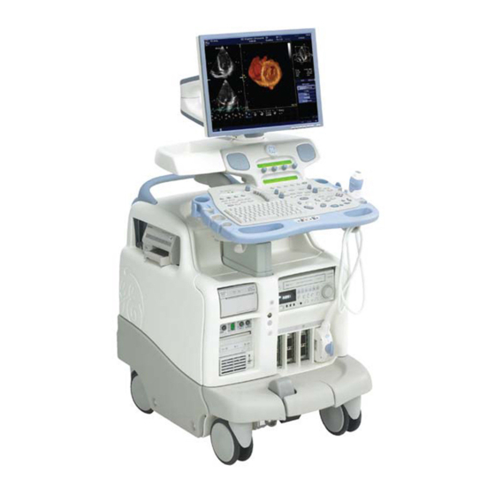
Doppler a number of combinations of the above • Vivid 7 / Vivid 7 PRO is a digital beam forming unit and can handle up to 192 element linear probes by use of multiplexing. • Signal flow from the Probe Connector Panel to the Front End, then to the Mid Processors and Backend Processor and finally to the monitor and peripherals. - Page 27 Upper Panel With Stereo Loudspeakers Control Panel B/w Video Printer Doppler (PEDOF) connector Probe Connectors Parking Slot Brake Pedals Patient I/O MO Disk CD-R Drive Figure 1-1 Vivid 7 / Vivid 7 PRO Major Components Chapter 1 - Introduction 1 - 3...
- Page 28 MCD rev. 07 includes a FB200060 RLY-3 noisefix for use of PAMPTE probe. For Vivid 7 produced before FB200170 TX128-2. June 3, 2002 and for Vivid 7 Replacement for FB200170 FC200022 TX128-3 used on Vivid 7 produced after June 3, 2002 FB200831 RX128-3B...
- Page 29 GE M EDICAL YSTEMS FC091194, R 7 / V 7 PRO S IRECTION EVISION IVID IVID ERVICE ANUAL 1-1-4-2 History - Hardware/Software Versions (cont’d) Table 1-4 Required Revisions for Cards and Modules Backend Rack BT’01 BT’01 BT’02 (sw. 1.0) (sw. 1.0 / 1.1 / 1.2) (sw.
- Page 30 GE M EDICAL YSTEMS FC091194, R 7 / V 7 PRO S IRECTION EVISION IVID IVID ERVICE ANUAL 1-1-4-3 History - Supported Probes Table 1-5 Supported Probes and SW Versions SUPPORTED MODELS & SW VERSION PART PROBES NUMBER NAME BT-01, V7...
-
Page 31: Purpose Of Operator Manual(S)
1-1-5 Purpose of Operator Manual(s) The Operator Manual(s) should be fully read and understood before operating the Vivid 7 / Vivid 7 PRO and also kept near the unit for quick reference. Chapter 1 - Introduction... -
Page 32: Important Conventions
Important Conventions 1-2-1 Conventions Used in Book 1-2-1-1 Model Designations. This manual covers the Vivid 7 / Vivid 7 PRO scanners listed in Table 1-2. 1-2-1-2 Icons. Pictures, or icons, are used wherever they will reinforce the printed message. The icons, labels and conventions used on the product and in the service information are described in this chapter. -
Page 33: Standard Hazard Icons
GE M EDICAL YSTEMS FC091194, R 7 / V 7 PRO S IRECTION EVISION IVID IVID ERVICE ANUAL 1-2-2 Standard Hazard Icons Important information will always be preceded by the exclamation point contained within a triangle, as seen throughout this chapter. In addition to text, several different graphical icons (symbols) may be used to make you aware of specific types of hazards that could possibly cause harm. -
Page 34: Product Icons
IPX8 indicates drip proof and may be IP Code (IPX8/IP68) Footswitch used in an Operating Theater. The footswitch delivered with Vivid 7 / Vivid 7 PRO is IP68 rated. Equipment Type BF (man in the box Probe connectors including Doppler... - Page 35 GE M EDICAL YSTEMS FC091194, R 7 / V 7 PRO S IRECTION EVISION IVID IVID ERVICE ANUAL Table 1-8 Product Icons (continued) LABEL/SYMBOL PURPOSE/MEANING LOCATION “ATTENTION - Consult accompanying documents” is intended to alert the user Various to refer to the operator manual or other instructions when complete information cannot be provided on the label.
-
Page 36: Safety Considerations
Human Safety Operating personnel must not remove the system covers. Servicing should be performed by authorized personnel only. Only personnel who have participated in a Vivid 7 / Vivid 7 PRO Training Seminar are authorized to service the equipment. 1-3-3... -
Page 37: Electrical Safety
1-3-3 Mechanical Safety (cont’d) VIVID 7 / VIVID 7 PRO weighs 190 kg (419 lbs) or more, depending on installed peripherals, when CAUTION ready for use. Care must be used when moving it or replacing its parts. Failure to follow the precautions listed below could result in injury, uncontrolled motion and costly damage. -
Page 38: Labels Locations
Labels on Front of Monitor and Control Panel DESCRIPTION ILLUSTRATION Label, Vivid 7 (Monitor) - BT’01 Label, Vivid 7 (Monitor) - BT’02 Label, Vivid 7 PRO (Monitor) - BT’02 Label, GE Logo 1 - 14 Section 1-3 - Safety Considerations... - Page 39 GE M EDICAL YSTEMS FC091194, R 7 / V 7 PRO S IRECTION EVISION IVID IVID ERVICE ANUAL Table 1-9 Labels on Front of Monitor and Control Panel (continued) DESCRIPTION ILLUSTRATION press once ON/OFF: FC314104 03 Label, On/Off Switch (Two versions of the label have been used, the one to the right is the latest version.)
- Page 40 GE M EDICAL YSTEMS FC091194, R 7 / V 7 PRO S IRECTION EVISION IVID IVID ERVICE ANUAL 1-3-5-2 Labels on Front Handle Table 1-10 Labels on Front Handle DESCRIPTION ILLUSTRATION Label, Front Handle (Three versions of the label have been used.
- Page 41 GE M EDICAL YSTEMS FC091194, R 7 / V 7 PRO S IRECTION EVISION IVID IVID ERVICE ANUAL 1-3-5-3 Labels Near Connectors on Front Table 1-11 Labels Near Connectors on Front DESCRIPTION ILLUSTRATION Label, Probe Connector (The Label, “Probe Connector” consists of three labels, named;...
- Page 42 GE M EDICAL YSTEMS FC091194, R 7 / V 7 PRO S IRECTION EVISION IVID IVID ERVICE ANUAL 1-3-5-4 Label on External I/O Table 1-12 Label, External I/O DESCRIPTION ILLUSTRATION Label, External. I/O 1 - 18 Section 1-3 - Safety Considerations...
- Page 43 GE M EDICAL YSTEMS FC091194, R 7 / V 7 PRO S IRECTION EVISION IVID IVID ERVICE ANUAL 1-3-5-5 Labels at AC Mains Inlet and Circuit Breaker Table 1-13 Labels at AC Mains Inlet and Circuit Breaker (used before May 2002)
- Page 44 GE M EDICAL YSTEMS FC091194, R 7 / V 7 PRO S IRECTION EVISION IVID IVID ERVICE ANUAL Table 1-13 Labels at AC Mains Inlet and Circuit Breaker (used before May 2002) (continued) DESCRIPTION ILLUSTRATION Hospital Grade Ground (GND) Label. (Used on some Label, GND-symbol., Hospital Grade...
- Page 45 DESCRIPTION ILLUSTRATION Label, General Info (Located on rear of system) Label used for Vivid 7 before 2 May 2002 Label, General Info (Located on rear of system) Label used for Vivid 7 after 2 May 2002 Chapter 1 - Introduction...
- Page 46 Label on Rear Cover (continued) DESCRIPTION ILLUSTRATION Label, General Info (Located on rear of system) Label used for Vivid 7 to China Label, General Info (Located on rear of system) Label used for Vivid 7 PRO 1 - 22 Section 1-3 - Safety Considerations...
- Page 47 7 PRO S IRECTION EVISION IVID IVID ERVICE ANUAL Table 1-15 Label on Rear Cover (continued) DESCRIPTION ILLUSTRATION Label, General Info (Located on rear of system) Label used for Vivid 7 PRO to China Chapter 1 - Introduction 1 - 23...
- Page 48 GE M EDICAL YSTEMS FC091194, R 7 / V 7 PRO S IRECTION EVISION IVID IVID ERVICE ANUAL 1-3-5-7 Labels on Internal I/O (Inside Scanner) Label on Front End Card Cage Side of Internal I/O Figure 1-2 Labels on Internal I/O (Inside Scanner), Front End Card Cage Side of Internal I/O...
- Page 49 GE M EDICAL YSTEMS FC091194, R 7 / V 7 PRO S IRECTION EVISION IVID IVID ERVICE ANUAL 1-3-5-8 Labels on Internal I/O (Inside Scanner) Label on Backend Processor Side of Internal I/O Figure 1-3 Labels on Internal I/O (Inside Scanner), Backend Processor Side of Internal I/O...
- Page 50 GE M EDICAL YSTEMS FC091194, R 7 / V 7 PRO S IRECTION EVISION IVID IVID ERVICE ANUAL 1-3-5-9 Label, Internal Connections (Int.Conn.) - Part 1, Left Part of Label Located on the outside of the Front End Card Rack’s cover (inside unit).Different versions of the label has been used since production start.
- Page 51 GE M EDICAL YSTEMS FC091194, R 7 / V 7 PRO S IRECTION EVISION IVID IVID ERVICE ANUAL 1-3-5-10 Label, Internal Connections (Int.Conn.) - Part 2, Right Part of Label Located on the outside of the Front End Card Rack’s cover (inside unit). Different versions of the label has been used since production start.
- Page 52 GE M EDICAL YSTEMS FC091194, R 7 / V 7 PRO S IRECTION EVISION IVID IVID ERVICE ANUAL 1-3-5-11 Label, Internal Connections (Int.Conn.) - Upper Part Located on the outside of the Backend Processor’s Cover (inside unit) Figure 1-6 Label, Internal Connections (Int.Conn.), Upper Part...
- Page 53 GE M EDICAL YSTEMS FC091194, R 7 / V 7 PRO S IRECTION EVISION IVID IVID ERVICE ANUAL 1-3-5-12 Label, Internal Connections (Int.Conn.) - Lower Part Located on the outside of the Backend Processor’s Cover (inside unit) Figure 1-7 Label, Internal Connections (Int.Conn.) - Lower Part...
- Page 54 GE M EDICAL YSTEMS FC091194, R 7 / V 7 PRO S IRECTION EVISION IVID IVID ERVICE ANUAL 1-3-5-13 Label, Internal Connections (Int.Conn.) - Upper Part Located on the outside of the Backend Processor’s Cover (inside unit) Figure 1-8 Label, Internal Connections (Int.Conn.), Upper Part...
- Page 55 GE M EDICAL YSTEMS FC091194, R 7 / V 7 PRO S IRECTION EVISION IVID IVID ERVICE ANUAL 1-3-5-14 Label, Internal Connections (Int.Conn.) - Lower Part Located on the outside of the Backend Processor’s Cover (inside unit) Figure 1-9 Label, Internal Connections (Int.Conn.) - Lower Part...
- Page 56 GE M EDICAL YSTEMS FC091194, R 7 / V 7 PRO S IRECTION EVISION IVID IVID ERVICE ANUAL 1-3-5-15 Label, Disassembly Nester, Part 1 (Left Part of Label) Located on the outside of the Front End Card Rack’s Cover (inside unit) DISASSEMBLY INSTRUCTIONS Remove all screws on rear side of monitor cover, and remove cover.
- Page 57 GE M EDICAL YSTEMS FC091194, R 7 / V 7 PRO S IRECTION EVISION IVID IVID ERVICE ANUAL 1-3-5-16 Label, Disassembly Nester, Part 2 (Right Part of Label) Located on the outside of the Front End Card Rack’s Cover (inside unit)
- Page 58 GE M EDICAL YSTEMS FC091194, R 7 / V 7 PRO S IRECTION EVISION IVID IVID ERVICE ANUAL 1-3-5-17 Labels on Footswitch Table 1-16 Labels on Footswitch DESCRIPTION ILLUSTRATION Label, Footswitch Footswitch, underneath 1 - 34 Section 1-3 - Safety Considerations...
- Page 59 GE M EDICAL YSTEMS FC091194, R 7 / V 7 PRO S IRECTION EVISION IVID IVID ERVICE ANUAL Table 1-16 Labels on Footswitch (continued) DESCRIPTION ILLUSTRATION LABEL, GE VINGMED LABEL, GE MEDICAL SYSTEMS Chapter 1 - Introduction 1 - 35...
-
Page 60: Dangerous Procedure Warnings
GE M EDICAL YSTEMS FC091194, R 7 / V 7 PRO S IRECTION EVISION IVID IVID ERVICE ANUAL 1-3-6 Dangerous Procedure Warnings Warnings, such as the example below, precede potentially dangerous procedures throughout this manual. Instructions contained in the warnings must be followed. -
Page 61: Emc, Emi, And Esd
1-4-2 CE Compliance Vivid 7 / Vivid 7 PRO conforms to all applicable conducted and radiated emission limits and to immunity from electrostatic discharge, radiated and conducted RF fields, magnetic fields and power line transient requirements. -
Page 62: Customer Assistance
Customer Answer Center Fax: +1-414-647-4125 Europe Tel: +49 212 2802 208 - CARDIAC GE Ultraschall Deutschland GmbH& Co. KG +49 212 2802 207 - GENERAL IMAGING BeethovenstraBe 239 Postfach 11 05 60, D-42655 Solingen Fax: +49 212 2802 431 Germany... -
Page 63: System Manufacture
IVID ERVICE ANUAL 1-5-2 System Manufacture Table 1-18 System Manufacture MANUFACTURER PHONE NUMBER FAX NUMBER GE Vingmed Ultrasound A/S Strandpromenaden 45 +47 3302 1100 +47 3302 1350 P.O. Box 141 N-3191 HORTEN NORWAY Chapter 1 - Introduction 1 - 39... - Page 64 GE M EDICAL YSTEMS FC091194, R 7 / V 7 PRO S IRECTION EVISION IVID IVID ERVICE ANUAL This page was intentionally left blank. 1 - 40 Section 1-5 - Customer Assistance...
-
Page 65: Pre-Installation
Purpose of Chapter 2 This chapter provides the information required to plan and prepare for the installation of a Vivid 7 / Vivid 7 PRO. Included are descriptions of the facility and electrical needs to be met by the purchaser of the unit. -
Page 66: General Console Requirements
2-2-1-1 Cooling The cooling requirement for the Vivid 7 / Vivid 7 PRO is 3500 BTU/hr. This figure does not include cooling needed for lights, people, or other equipment in the room. Each person in the room places an additional 300 BTU/hr. demand on the cooling system. -
Page 67: Electrical Requirements
2-2-2-5 Unit Power Plug If the unit arrives without a power plug, or with the wrong plug, you must contact your GE dealer or the installation engineer must supply what is locally required. Chapter 2 - Pre-Installation... -
Page 68: Emi Limitations
Ultrasound machines are susceptible to Electromagnetic Interference (EMI) from radio frequencies, magnetic fields, and transients in the air or wiring. They also generate EMI. The Vivid 7 / Vivid 7 PRO complies with limits as stated on the EMC label. However there is no guarantee that interference will not occur in a particular installation. - Page 69 Never place a label where RF gaskets meet the unit. Otherwise, the gap created will permit RF gaskets touch metal RF leakage. Or, if a label has been found in such a position, move the label. Use GE specified The interconnect cables are grounded and require ferrite beads and other shielding. Also, harnesses and peripherals cable length, material, and routing are all important;...
-
Page 70: Probes Environmental Requirements
Site preparation takes time. Begin Pre-installation checks as soon as possible, if possible, six weeks before delivery, to allow enough time to make any changes. Have two people available to deliver and unpack the Vivid 7 / Vivid 7 PRO. CAUTION Attempts to move the unit considerable distances or on an incline by one person could result in injury or damage or both. -
Page 71: Facility Needs
All electrical work on these products must comply with the requirements of applicable electrical codes. The purchaser of GE equipment must only utilize qualified personnel to perform electrical servicing on the equipment. -
Page 72: Required Facility Needs
Power outlet and place for any external peripheral are within 2 m (6.5 ft) of each other with peripheral within 1 m of the unit to connect cables. NOTE: The Vivid 7 / Vivid 7 PRO has four outlets inside the unit. One is for the monitor and three for on board peripherals. •... -
Page 73: Desirable Features
• Nearby waiting room, lavatory, and dressing room • Dual level lighting (bright and dim) • Lockable cabinet ordered by GE for its software and proprietary manuals 2-3-4 Minimal Floor Plan Suggestion Scale: Each square equals one square foot (app. 31 x 31 cm) -
Page 74: Networking Pre-Installation Requirements
Entries must include: • A host name, local port number, AE Title, IP address and Net Mask for the Vivid 7 / Vivid 7 PRO. • The IP addresses for the default gateway and other routers at the site for ROUTING INFORMATION. - Page 75 7 / V 7 PRO S IRECTION EVISION IVID IVID ERVICE ANUAL 2-3-5 Networking Pre-installation Requirements (cont’d). Vivid 7 / Vivid 7 PRO IP Address Local Port Host Name AE Title Net Mask ROUTING INFORMATION GATEWAY IP Addresses Destination IP Addresses...
- Page 76 GE M EDICAL YSTEMS FC091194, R 7 / V 7 PRO S IRECTION EVISION IVID IVID ERVICE ANUAL This page was intentionally left blank. 2 - 12 Section 2-3 - Facility Needs...
-
Page 77: Overview
3-1-1 Purpose of Chapter 3 This chapter contains information needed to install Vivid 7 / Vivid 7 PRO. Included is a procedure that describes how to receive and unpack the equipment and how to file a damage or loss claim. -
Page 78: Installation Warnings
CAUTION performance and cooling require this. OPERATOR MANUAL(S) CAUTION The User Manual(s) should be fully read and understood before operating the Vivid 7 / Vivid 7 PRO and kept near the unit for quick reference. Acoustic Output Hazard CAUTION Although the ultrasound energy transmitted from the Vivid 7 / Vivid 7 PRO probe is within AIUM/ NEMA standards, avoid unnecessary exposure. -
Page 79: Receiving And Unpacking The Equipment
Transportation“ on page in the beginning of this manual. We strongly advice you to store the Vivid 7 / Vivid 7 PRO packing material in undamaged condition in case of future transportation. The weight of the special designed wooden transportation box, with a Vivid 7 / Vivid 7 PRO and other normal equipment included, is approximate 300 kg (615 lbs). -
Page 80: Receiving Vivid 7 / Vivid 7 Pro
Receiving Vivid 7 / Vivid 7 PRO 3-4-1 Introduction Vivid 7 / Vivid 7 PRO is a fine tuned electronic equipment, and should be treated properly during transportation. NOTE: If the box is damaged or if the tilt & drop indicators show failure, please inform the sales representative immediately. -
Page 81: Unpacking Vivid 7 / Vivid 7 Pro
“Labank” On the first version transportation box, which On the second version transportation box, the ramp is placed is no longer manufactured by GE, a 10 cm directly on the labank ends. board (not furnished) is placed as a support under the upper end of the ramp. - Page 82 Step Task The rear wheels on Vivid 7 / Vivid 7 PRO do not have a direction lock. That is why the instrument has to be removed through the rear end of the Transportation Box. Press once on the brake pedal to release the brakes. Keep direction lock activated. The direction lock keeps the front wheels from swiveling and blocking the system inside the narrow transportation box.
-
Page 83: Transportation Box Dimensions
GE M EDICAL YSTEMS FC091194, R 7 / V 7 PRO S IRECTION EVISION IVID IVID ERVICE ANUAL 3-5-1 Transportation Box Dimensions 159 cm 130 cm 80 cm On first version box: 3 cm protruding ends in front Figure 3-2 Transportation box dimensions... -
Page 84: Preparing For Installation
• Verify that the specifications below don’t conflict with any on site conditions 3-7-1-2 Physical Dimensions The physical dimensions of the Vivid 7 / Vivid 7 PRO unit are summarized in Table 3-5. Table 3-5 Physical Dimensions of Vivid 7 / Vivid 7 PRO with monitor and peripherals... -
Page 85: Electrical Specifications
IVID IVID ERVICE ANUAL 3-7-2 Electrical Specifications CONNECTING A Vivid 7 / Vivid 7 PRO UNIT TO THE WRONG VOLTAGE LEVEL WILL WARNING WARNING MOST LIKELY DESTROY THE UNIT. 3-7-2-1 Verification of the System’s Voltage Settings Verify that the mains voltage specified for the unit is available on site. -
Page 86: Connect Footswitch
IVID ERVICE ANUAL 3-7-3 Connect Footswitch Connect Footswitch to External I/O at the rear side of Vivid 7 / Vivid 7 PRO. When not in use, store it in the tray below. Footswitch connection Figure 3-4 Footswitch connection 3-7-4 Connect Telephone Line to Modem Connector... -
Page 87: Connect Ecg
IVID ERVICE ANUAL 3-7-5 Connect ECG Connect ECG to Patient I/O Module in the front of Vivid 7 / Vivid 7 PRO. ECG connection Figure 3-6 ECG connection to Patient I/O Module 3-7-6 Connect Phono Connect Phono to Patient I/O Module in the front of Vivid 7 / Vivid 7 PRO. -
Page 88: Connect Pulse Pressure Transducer
IVID ERVICE ANUAL 3-7-7 Connect Pulse Pressure Transducer Connect Pulse Pressure Transducer to Patient I/O Module in the front of Vivid 7 / Vivid 7 PRO. Pulse Pressure Transducer connection Figure 3-8 Pulse Pressure Transducer connection 3-7-8 Connect Ethernet Connect Ethernet to External I/O at the rear side of Vivid 7 / Vivid 7 PRO. -
Page 89: Probe Connection
3-7-9 Probe Connection Vivid 7 / Vivid 7 PRO has four positions to plug in probes. The connector to the left is a “dummy” connector, only used for parking one probe. The three other connectors are selectable and used for scanning. -
Page 90: Power On/Boot Up
GE M EDICAL YSTEMS FC091194, R 7 / V 7 PRO S IRECTION EVISION IVID IVID ERVICE ANUAL 3-7-10 Power ON/Boot Up 3-7-10-1 Connecting Mains Power to the Unit Never use a three-to-two prong adapter; this defeats the safety ground. - Page 91 GE M EDICAL YSTEMS FC091194, R 7 / V 7 PRO S IRECTION EVISION IVID IVID ERVICE ANUAL 3-7-10-2 Turn Unit ON Table 3-9 Turn Unit ON Step Task Expected Result(s) Switch ON the Mains Power Circuit Breaker at the rear of the unit.
- Page 92 GE M EDICAL YSTEMS FC091194, R 7 / V 7 PRO S IRECTION EVISION IVID IVID ERVICE ANUAL Table 3-9 Turn Unit ON (continued) Step Task Expected Result(s) The software initiates and set up the Card Rack and the rest of the instrument.
-
Page 93: Power Shut Down
GE M EDICAL YSTEMS FC091194, R 7 / V 7 PRO S IRECTION EVISION IVID IVID ERVICE ANUAL 3-7-11 Power Shut Down 3-7-12 Switching OFF the Unit "Power Shut Down" on page 4-5 for a detailed description. 1.) Press the ON/OFF button on the top left of the Control Panel to display the Exit dialog window. - Page 94 GE M EDICAL YSTEMS FC091194, R 7 / V 7 PRO S IRECTION EVISION IVID IVID ERVICE ANUAL 3-7-12-2 Power Shut Down to Standby Mode (cont’d) Figure 3-12 System - Exit menu The System - Exit menu gives you the following choices: Logoff Use this button to log off the current user.
- Page 95 GE M EDICAL YSTEMS FC091194, R 7 / V 7 PRO S IRECTION EVISION IVID IVID ERVICE ANUAL 3-7-12-3 Full Power Shut Down This procedure describes the needed steps to do a complete power down of the system: 1.) Press the ON/OFF key on the Control Panel once to display the System - Exit menu on the screen.
- Page 96 GE M EDICAL YSTEMS FC091194, R 7 / V 7 PRO S IRECTION EVISION IVID IVID ERVICE ANUAL 3-7-12-3 Full Power Shut Down (cont’d) 2.) Click SHUTDOWN to do a complete power down of the unit. Backend Processor will first turn OFF the Scanner activity and print the message “Please wait - Shutdown in progress”...
-
Page 97: Configuration
ANUAL Section 3-8 Configuration OVERVIEW Table 3-10 Contents in Section 3-5 Sub-section Description Page Number 3-8-1 Vivid 7 / Vivid 7 PRO Configuration 3-21 3-8-1-1 Log on to the system 3-22 3-8-1-2 Enter Location 3-24 3-8-1-3 Date and Time Adjustments... -
Page 98: Vivid 7 / Vivid 7 Pro Configuration
7 PRO S IRECTION EVISION IVID IVID ERVICE ANUAL 3-8-1 Vivid 7 / Vivid 7 PRO Configuration 3-8-1-1 Log on to the system Table 3-11 Log on to the system Step Task Expected Result(s) The Operator Login window is displayed. - Page 99 GE M EDICAL YSTEMS FC091194, R 7 / V 7 PRO S IRECTION EVISION IVID IVID ERVICE ANUAL Table 3-11 Log on to the system (continued) Step Task Expected Result(s) The System Setup window is displayed Click SYSTEM to select the System Setup window.
- Page 100 GE M EDICAL YSTEMS FC091194, R 7 / V 7 PRO S IRECTION EVISION IVID IVID ERVICE ANUAL 3-8-1-2 Enter Location Figure 3-16 Hospital and Department Name Table 3-12 Location Name Step Task Expected Result(s) Open the Configuration Window as described in 3-8-1-1 "Log on...
- Page 101 GE M EDICAL YSTEMS FC091194, R 7 / V 7 PRO S IRECTION EVISION IVID IVID ERVICE ANUAL 3-8-1-3 Date and Time Adjustments Figure 3-17 Date and Time Adjustments Table 3-13 Date and Time adjustments Step Task Expected Result(s) Open the Configuration Window as described in 3-8-1-1 "Log on...
- Page 102 GE M EDICAL YSTEMS FC091194, R 7 / V 7 PRO S IRECTION EVISION IVID IVID ERVICE ANUAL 3-8-1-4 Language Selection Language Figure 3-18 Language Selection Table 3-14 Language Adjustments Step Task Expected Result(s) Open the Configuration Window as described in 3-8-1-1 "Log on...
- Page 103 GE M EDICAL YSTEMS FC091194, R 7 / V 7 PRO S IRECTION EVISION IVID IVID ERVICE ANUAL 3-8-1-5 Units of Measure Units Figure 3-19 Select Units of Measure Table 3-15 Select Units of Measure Step Task Expected Result(s) Open the Configuration Window as described in 3-8-1-1 "Log on...
-
Page 104: Service Screen
GE M EDICAL YSTEMS FC091194, R 7 / V 7 PRO S IRECTION EVISION IVID IVID ERVICE ANUAL 3-8-2 Service Screen 3-8-2-1 Overview The Service Screen gives you access to; • select Video Format to be used by VCR •... - Page 105 Select Video Cassette Recorder (VCR) Type Use the VCR drop down menu to select VCR type. See "Approved On-board Peripherals" on page 3- for approved VCRs for use with Vivid 7 / Vivid 7 PRO. Select Video Player Figure 3-22 Select Video Player...
- Page 106 GE M EDICAL YSTEMS FC091194, R 7 / V 7 PRO S IRECTION EVISION IVID IVID ERVICE ANUAL 3-8-2-6 Keyboard Setup Click KEYBOARD SETUP to get access to Keyboard Properties Select Keyboard setup Figure 3-24 Select Keyboard Setup The Keyboard Properties window has controls for: •...
- Page 107 GE M EDICAL YSTEMS FC091194, R 7 / V 7 PRO S IRECTION EVISION IVID IVID ERVICE ANUAL 3-8-2-7 Add Printer Click Add Printer Figure 3-26 Select Add Printer Click ADD PRINTER to start the Add Printer (Installation) Wizard. Figure 3-27 Add Printer Wizard Follow the instructions in the Wizard to install a new printer.
-
Page 108: Optional Peripherals/Peripheral Connection
3-8-3 Optional Peripherals/Peripheral Connection 3-8-3-1 Approved On-board Peripherals The following list covers the on-board peripherals available for Vivid 7 / Vivid 7 PRO • Printer, Black & White, Video, Sony • Printer, Color, Video, Sony, both PAL and NTSC versions are available •... -
Page 109: Software Options Configuration
Prerequisite Password (Software Option Key) A Password enables the software option or combination of software options. This password is specific for each Vivid 7 / Vivid 7 PRO. 3-8-6-2 On site Configuration 1.) Press Config (See “Log on to the system” on page 3-22. for detailed description) 2.) Select the user adm... - Page 110 Figure 3-30 Software Option Key Incorrect password entry will result in loss of system options. CAUTION If password is incorrect, please contact your local GE Service representative. 8.) Type the Password (Software Option Key). 9.) Press OK to save the new setting.
-
Page 111: Connectivity
Section 3-9 Connectivity 3-9-1 Introduction The next pages describes how to connect the Vivid 7 / Vivid 7 PRO to a remote archive/work station or a DICOM service, using a TCP/IP connection. Major subjects discussed in this section; • "Physical Connection" on page 3-35 •... - Page 112 GE M EDICAL YSTEMS FC091194, R 7 / V 7 PRO S IRECTION EVISION IVID IVID ERVICE ANUAL 3-9-2-2 Local Network Connection to EchoPAC PC Workstation Do not use the fifth connector and the switch can be in any position,...
-
Page 113: Connectivity Setup
GE M EDICAL YSTEMS FC091194, R 7 / V 7 PRO S IRECTION EVISION IVID IVID ERVICE ANUAL 3-9-3 Connectivity Setup NOTE: If connected as a stand-alone network (only scanner, EchoPAC PC work station and eventually a network printer in a separate network), you should use default delivery settings. - Page 114 GE M EDICAL YSTEMS FC091194, R 7 / V 7 PRO S IRECTION EVISION IVID IVID ERVICE ANUAL 3-9-3-2 Select TCP/IP Set-up Screen (cont’d) 2.) Select CONNECTIVITY (in the lower part of the window) Connectivity Figure 3-35 Connectivity Opening Screen 3.) Select the TCP/IP TAB (it is named Tcpip).
- Page 115 IP address for Default Gateway NOTE: Do not enable DHCP. The use of DHCP is not supported. IP Address Subnet Mask Default Gateway Figure 3-37 TCP/IP Set-up for Vivid 7 / Vivid 7 PRO Chapter 3 - Installation 3 - 39...
- Page 116 The new settings are saved to a common settings file. After a restart, the settings are also included in other screens. 2.) Restart Vivid 7 / Vivid 7 PRO to make the changes take place. 3 - 40 Section 3-9 - Connectivity...
- Page 117 5.) Click the + beside the dataflow you want to check (here: Remote Archive - Remote HD) to see its contents. DATAFLOW button Click + Figure 3-40 Pre-configured Data flows in Vivid 7 / Vivid 7 PRO Chapter 3 - Installation 3 - 41...
- Page 118 GE M EDICAL YSTEMS FC091194, R 7 / V 7 PRO S IRECTION EVISION IVID IVID ERVICE ANUAL 3-9-3-6 Verification of a Connection Set Up to an EchoPAC PC Work Station (cont’d) Click once to highlight server’s name Figure 3-41 Remote HD dataflow contents The Remote Archive - Remote HD includes an EchoPAC PC with one Service also called Remote Archive - Remote HD.
- Page 119 The cause may be; the setup of the network information, either on Vivid 7 / Vivid 7 PRO or on the EchoPAC PC, or the network connection is broken somewhere between the Vivid 7 / Vivid 7 PRO and the EchoPAC PC.
- Page 120 GE M EDICAL YSTEMS FC091194, R 7 / V 7 PRO S IRECTION EVISION IVID IVID ERVICE ANUAL 3-9-3-6 Verification of a Connection Set Up to an EchoPAC PC Work Station (cont’d) 8.) Click the DATAFLOW tab to view the Dataflow Services window.
- Page 121 GE M EDICAL YSTEMS FC091194, R 7 / V 7 PRO S IRECTION EVISION IVID IVID ERVICE ANUAL 3-9-3-6 Verification of a Connection Set Up to an EchoPAC PC Work Station (cont’d) Remote Archive - Remote HD Figure 3-46 Remote Archive - Remote HD Dataflow Contents Overview...
- Page 122 GE M EDICAL YSTEMS FC091194, R 7 / V 7 PRO S IRECTION EVISION IVID IVID ERVICE ANUAL 3-9-3-6 Verification of a Connection Set Up to an EchoPAC PC Work Station (cont’d) 10.)Select the SERVICES tab (located near the top of the window).
- Page 123 GE M EDICAL YSTEMS FC091194, R 7 / V 7 PRO S IRECTION EVISION IVID IVID ERVICE ANUAL 3-9-3-6 Verification of a Connection Set Up to an EchoPAC PC Work Station (cont’d) 12.)Verify that the IP-address is correct, indicating that you have selected the right unit.
- Page 124 GE M EDICAL YSTEMS FC091194, R 7 / V 7 PRO S IRECTION EVISION IVID IVID ERVICE ANUAL 3-9-3-6 Verification of a Connection Set Up to an EchoPAC PC Work Station (cont’d) 13.)In the list of “Services”, select “Remote Archive - Remote Storage”.
- Page 125 It may be necessary for the administrator to enter information about Vivid 7 / Vivid 7 PRO into the DICOM server’s set-up. This information is typically Vivid 7 / Vivid 7 PRO’s AE Title and maybe also the IP address which he provides.
- Page 126 1.) Select CONNECTIVITY 2.) Click on the SERVICES tab. Vivid 7 / Vivid 7 PRO’s AE Title is listed below My Computer (here it is VIVID7-000000). Vivid 7 / Vivid 7 Figure 3-51 Vivid 7 / Vivid 7 PRO’s AE Title 3-9-3-7-6 Set-up of DICOM Server in Vivid 7 / Vivid 7 PRO’s Configuration Screens...
- Page 127 Set Up Connection to a DICOM Server in a Network (cont’d) 3-9-3-7-6 Set-up of DICOM Server in Vivid 7 / Vivid 7 PRO’s Configuration Screens (cont’d) 3.) Click once on the Pure DICOM Storage line under Services and the bottom part of the screen will be populated with set-up information for the DICOM server.
- Page 128 Set Up Connection to a DICOM Server in a Network (cont’d) 3-9-3-7-6 Set-up of DICOM Server in Vivid 7 / Vivid 7 PRO’s Configuration Screens (cont’d) 4.) Change the Name to a name you pick for the DICOM server (e.g. ProSolv server). It doesn’t really matter what this name is.
- Page 129 GE M EDICAL YSTEMS FC091194, R 7 / V 7 PRO S IRECTION EVISION IVID IVID ERVICE ANUAL 3-9-3-7-7 Check the Connection to the DICOM Server (Ping) 1.) After the system is rebooted, press Config, log on as adm (no password) and enter the Connectivity screen.
- Page 130 GE M EDICAL YSTEMS FC091194, R 7 / V 7 PRO S IRECTION EVISION IVID IVID ERVICE ANUAL 3-9-3-7-8 Setting the DICOM Server as Default Dataflow 1.) Finnish the verification in "Check the Connection to the DICOM Server (Ping)" on page 3-53.
- Page 131 GE M EDICAL YSTEMS FC091194, R 7 / V 7 PRO S IRECTION EVISION IVID IVID ERVICE ANUAL 3-9-3-7-9 Performing a Study 1.) After restart, hit New Exam (you’ll see that DICOM Server is the default dataflow), enter a last name and patient ID and start scanning and image acquisition.
-
Page 132: Installation Paperwork
GE M EDICAL YSTEMS FC091194, R 7 / V 7 PRO S IRECTION EVISION IVID IVID ERVICE ANUAL Section 3-10 Installation Paperwork NOTE: During and after installation, the documentation (i.e. User Manuals, Installation Manuals etc.) for the peripheral units must be kept as part of the original system documentation. This will ensure that all relevant safety and user informations are available during the operation and service of the complete system. -
Page 133: Complete The Post Delivery Check List
GE M EDICAL YSTEMS FC091194, R 7 / V 7 PRO S IRECTION EVISION IVID IVID ERVICE ANUAL 3-10-2 Complete the Post Delivery Check List Please fill in the enclosed form “Post Delivery Check List” (at the back of this reminder) and fax it to our System Test Department, Fax # +47 3302 1354, as soon as you have powered up and checked the system.This is most important for us to ensure top quality on our delivery. -
Page 134: Post Delivery Check List
ANUAL 3-10-3 Post Delivery Check List Fill in your observations and return the check list to: GE Vingmed Ultrasound Fax No.: +47 3302 1354 Attention: System Test Department System tester: ____________________________________________ (please use BLOCK LETTERS) Post Delivery Check List for Vivid______________ Serial NO:_____________________... -
Page 135: Functional Checks
Overview 4-1-1 Purpose of Chapter 4 This chapter provides procedures for quickly checking major functions of the Vivid 7 / Vivid 7 PRO scanner, diagnostics by using the built-in service software, and power supply adjustments. Table 4-1 Contents in chapter 4... -
Page 136: General Procedures
GE M EDICAL YSTEMS FC091194, R 7 / V 7 PRO S IRECTION EVISION IVID IVID ERVICE ANUAL Section 4-2 General Procedures 4-2-1 Power ON/ Boot Up 4-2-1-1 Connecting Mains Power to the Unit Never use a three-to-two prong adapter; this defeats the safety ground. - Page 137 GE M EDICAL YSTEMS FC091194, R 7 / V 7 PRO S IRECTION EVISION IVID IVID ERVICE ANUAL 4-2-1-2 Turn Unit ON Table 4-3 Turn Unit ON Step Task Expected Result(s) Switch ON the Mains Power Circuit Breaker at the rear of the unit.
- Page 138 GE M EDICAL YSTEMS FC091194, R 7 / V 7 PRO S IRECTION EVISION IVID IVID ERVICE ANUAL Table 4-3 Turn Unit ON (continued) Step Task Expected Result(s) The software initiates and set up the Card Rack and the rest of the instrument.
-
Page 139: Power Shut Down
GE M EDICAL YSTEMS FC091194, R 7 / V 7 PRO S IRECTION EVISION IVID IVID ERVICE ANUAL 4-2-2 Power Shut Down 4-2-2-1 Overview When the unit is switched off, the system performs an automatic shutdown sequence. The unit can be switched off into two states: •... - Page 140 GE M EDICAL YSTEMS FC091194, R 7 / V 7 PRO S IRECTION EVISION IVID IVID ERVICE ANUAL 4-2-2-2 Power Shut Down to Standby Mode (cont’d) Figure 4-2 System - Exit menu The System - Exit menu gives you the following choices: Logoff Use this button to log off the current user.
- Page 141 GE M EDICAL YSTEMS FC091194, R 7 / V 7 PRO S IRECTION EVISION IVID IVID ERVICE ANUAL 4-2-2-3 Full Power Shut Down This procedure describes the needed steps to do a complete power down of the system: 1.) Press the ON/OFF key on the Control Panel once to display the System - Exit menu on the screen.
- Page 142 GE M EDICAL YSTEMS FC091194, R 7 / V 7 PRO S IRECTION EVISION IVID IVID ERVICE ANUAL 4-2-2-3 Full Power Shut Down (cont’d) 2.) Click SHUTDOWN to do a complete power down of the unit. Backend Processor will first turn OFF the Scanner activity and print the message “Please wait - Shutdown in progress”...
-
Page 143: Using Removable Media
4-2-3-1 Introduction Vivid 7 / Vivid 7 PRO is equipped with a Magneto Optical Disk Drive (MO Drive) and a CD Drive. Both units are available from the front of the unit, below the Patient I/O panel. Magneto Optical Disk Drive... -
Page 144: Labeling Removable Media
Install CD-R Disk in CD Drive NOTE: CD-RW disks are NOT supported by Vivid 7 / Vivid 7 PRO, but CD-R disks may be used. 1.) Press the Eject button on the right side of the CD Drive once to open the disk tray. -
Page 145: Formatting Removable Media
GE M EDICAL YSTEMS FC091194, R 7 / V 7 PRO S IRECTION EVISION IVID IVID ERVICE ANUAL 4-2-5 Formatting Removable Media This procedure describes how to format an MO Disk or a CD-R disk. Before you continue, be sure about what naming convention you will use for labelling the Removable Media. -
Page 146: Archiving And Loading Presets
TASK FUNCTION Insert an empty, formatted MO disk labelled “PRESETS” and marked with Vivid 7 / Vivid 7 PRO’s serial number and the date, into the MO Drive (for formatting, see chapter 12 in the Vivid 7 User’s Manual). The Backup window is displayed. - Page 147 GE M EDICAL YSTEMS FC091194, R 7 / V 7 PRO S IRECTION EVISION IVID IVID ERVICE ANUAL Table 4-4 Saving Presets (continued) STEP TASK FUNCTION Press ALT + E on the alphanumeric The MO disk is ejected. keyboard. 4-2-7-2...
-
Page 148: Functional Checks
Keys and Trackball vary according to the scan mode and position that is currently active. 4-3-2-2 Assignable Rotary Knobs Vivid 7 / Vivid 7 PRO has four assignable rotary knobs. The assigned functions are indicated above the rotary on the LCD display. 4-3-2-3 Assignable Push Buttons Vivid 7 / Vivid 7 PRO has five Assignable Push Buttons. - Page 149 GE M EDICAL YSTEMS FC091194, R 7 / V 7 PRO S IRECTION EVISION IVID IVID ERVICE ANUAL 4-3-2-4 More The MORE button gives access to additional controls on the Assignable Push Buttons. 4-3-2-5 Soft Menu Control (4-way Rocker) The 4-way Rocker works together with the Soft menu on the screen.
-
Page 150: Performance Tests
Performance Tests 4-3-3-1 Recommended Test Phantoms GE Medical Systems recommends the RMI 430GS phantom. It is the most current phantom recommended to our field service personnel and provides the necessary targets and extended life necessary for consistent system testing. Lateral Distance... -
Page 151: 2D Mode (B Mode) Checks
GE M EDICAL YSTEMS FC091194, R 7 / V 7 PRO S IRECTION EVISION IVID IVID ERVICE ANUAL 4-3-4 2D Mode (B mode) Checks 4-3-4-1 Introduction The 2D Mode is the system’s default mode. Status Window Control Menu Figure 4-11 2D Mode Screen Example... - Page 152 GE M EDICAL YSTEMS FC091194, R 7 / V 7 PRO S IRECTION EVISION IVID IVID ERVICE ANUAL 4-3-4-2 Preparations (cont’d) Mode Dependant Keys Width Frequency Focus Frame rate Up/Down* Left/Right* Cineloop (in Freeze, only) B Color Maps Zoom Gain...
- Page 153 GE M EDICAL YSTEMS FC091194, R 7 / V 7 PRO S IRECTION EVISION IVID IVID ERVICE ANUAL 4-3-4-3 Check Width, Focus, Framerate, Frequency These 2D Mode Functions are located on Assignable Rotaries. The results of these adjustments must be verified on the 2D sector on the screen.
- Page 154 GE M EDICAL YSTEMS FC091194, R 7 / V 7 PRO S IRECTION EVISION IVID IVID ERVICE ANUAL 4-3-4-4 Check Up/Down, Left/Right, B Color Maps and Cineloop These 2D Mode Functions are located on Mode Dependant Keys (Push Buttons) The results of these adjustments must be verified on the 2D sector on the screen.
- Page 155 GE M EDICAL YSTEMS FC091194, R 7 / V 7 PRO S IRECTION EVISION IVID IVID ERVICE ANUAL 4-3-4-5 Check Gain, TGC and Depth Table 4-8 2D Mode: Check Gain, TGC and Depth in 2D Mode Step Task Expected Result...
- Page 156 GE M EDICAL YSTEMS FC091194, R 7 / V 7 PRO S IRECTION EVISION IVID IVID ERVICE ANUAL 4-3-4-6 2D Soft Menu Controls Table 4-9 4-way rocker used for Soft Menu control DESCRIPTION A 4-way rocker (4-way multi direction switch) used to;...
- Page 157 GE M EDICAL YSTEMS FC091194, R 7 / V 7 PRO S IRECTION EVISION IVID IVID ERVICE ANUAL 4-3-4-8 Check DDP, Diff, Power and Dynamic Range Table 4-11 2D Mode: Check DDP, Diff, Power and Dynamic Range Step Task Expected Result(s)
-
Page 158: M Mode Checks
GE M EDICAL YSTEMS FC091194, R 7 / V 7 PRO S IRECTION EVISION IVID IVID ERVICE ANUAL 4-3-5 M Mode Checks 4-3-5-1 Introduction Figure 4-13 M-Mode Screen Example 4-3-5-2 Preparations Use a phantom when doing these tests. 1.) Connect one of the probes, to the scanner’s left-most probe connector. - Page 159 GE M EDICAL YSTEMS FC091194, R 7 / V 7 PRO S IRECTION EVISION IVID IVID ERVICE ANUAL 4-3-5-2 Preparations (cont’d) Mode Dependant Keys Horizontal Sweep* Frequency Focus Contour Up/Down Gain * Zoom Cursor Zoom Steer Display zoom HR zoom M-Mode Act.
- Page 160 GE M EDICAL YSTEMS FC091194, R 7 / V 7 PRO S IRECTION EVISION IVID IVID ERVICE ANUAL 4-3-5-3 Check Horizontal Sweep, Frequency, Focus and Contour Table 4-12 M-Mode: Check Horizontal Sweep, Frequency, Focus and Contour Step Task Expected Result(s)
- Page 161 GE M EDICAL YSTEMS FC091194, R 7 / V 7 PRO S IRECTION EVISION IVID IVID ERVICE ANUAL 4-3-5-4 Check Compress, Reject, Power and Dynamic Range Table 4-13 M-Mode Soft menu Controls check Step Task Expected Result(s) Adjust Compress Controls the amount of contrast in the image.
-
Page 162: Color Mode Checks
GE M EDICAL YSTEMS FC091194, R 7 / V 7 PRO S IRECTION EVISION IVID IVID ERVICE ANUAL 4-3-6 Color Mode Checks 4-3-6-1 Introduction Color Flow screens is 2D or M Mode screens with colors representing blood or tissue movement. - Page 163 GE M EDICAL YSTEMS FC091194, R 7 / V 7 PRO S IRECTION EVISION IVID IVID ERVICE ANUAL 4-3-6-2 Preparations (cont’d) Mode Dependant Keys Horiz. sweep (Color M-Mode only) * Scale Baseline * Invert * Variance * Color maps *...
- Page 164 GE M EDICAL YSTEMS FC091194, R 7 / V 7 PRO S IRECTION EVISION IVID IVID ERVICE ANUAL 4-3-6-5 Check Horizontal Sweep, PRF, Baseline, LVR and Invert Table 4-14 Color Flow Mode Controls Check Step Task Expected Result(s) Adjust Horizontal Sweep (Color M-Mode only) Adjusts the horizontal refresh rate of the M-Mode area of the display.
- Page 165 GE M EDICAL YSTEMS FC091194, R 7 / V 7 PRO S IRECTION EVISION IVID IVID ERVICE ANUAL 4-3-6-6 Check Variance, Color Maps and Cineloop Table 4-15 Color Flow Mode: Check Variance, Color Maps and Cineloop Step Task Expected Result(s)
- Page 166 GE M EDICAL YSTEMS FC091194, R 7 / V 7 PRO S IRECTION EVISION IVID IVID ERVICE ANUAL Table 4-16 Color Flow Mode: Check Variance, Color Maps and Cineloop Step Task Expected Result(s) Select Color Maps Displays a menu of color map options.
- Page 167 GE M EDICAL YSTEMS FC091194, R 7 / V 7 PRO S IRECTION EVISION IVID IVID ERVICE ANUAL Table 4-17 Color-Mode Soft Menu Controls Check Step Task Expected Result(s) Adjust Power Controls the amount of acoustic power applied in all modes.
-
Page 168: Doppler Mode Checks
GE M EDICAL YSTEMS FC091194, R 7 / V 7 PRO S IRECTION EVISION IVID IVID ERVICE ANUAL 4-3-7 Doppler Mode Checks 4-3-7-1 Introduction Doppler is used to measure velocity (most often in blood). Doppler mode can be done with a special pencil probe or with an ordinary probe. By using an ordinary probe, you can first bring up a 2D picture for navigation purpose and then add Doppler. - Page 169 GE M EDICAL YSTEMS FC091194, R 7 / V 7 PRO S IRECTION EVISION IVID IVID ERVICE ANUAL 4-3-7-2 Preparations (cont’d) Mode Dependant Keys Horizontal Sweep * Velocity Range Baseline * Invert * LPRF (in PW mode only) Color Maps *...
- Page 170 GE M EDICAL YSTEMS FC091194, R 7 / V 7 PRO S IRECTION EVISION IVID IVID ERVICE ANUAL 4-3-7-3 Check Horizontal Sweep, Velocity Range, Baseline and Low Velocity Reject Table 4-19 Doppler Mode Controls Checks Step Task Expected Result(s) Adjust HORIZONTAL SWEEP Adjusts the horizontal refresh rate of the Doppler area of the display.
- Page 171 GE M EDICAL YSTEMS FC091194, R 7 / V 7 PRO S IRECTION EVISION IVID IVID ERVICE ANUAL 4-3-7-4 Check Invert, LPRF (in PW only) and Color Maps Table 4-20 Doppler Mode Controls Checks Step Task Expected Result(s) Press INVERT...
- Page 172 GE M EDICAL YSTEMS FC091194, R 7 / V 7 PRO S IRECTION EVISION IVID IVID ERVICE ANUAL 4-3-7-5 Check Sample Volume, Compress, Reject and Frequency Table 4-21 PW/CW Doppler Mode: Check Sample Volume, Compress, Reject and Frequency Step Task...
- Page 173 GE M EDICAL YSTEMS FC091194, R 7 / V 7 PRO S IRECTION EVISION IVID IVID ERVICE ANUAL 4-3-7-6 Check Frame Rate, Angle Correction and Power Table 4-22 PW/CW Doppler Mode: Check Frame Rate, Angle Correction and Power Step Task...
-
Page 174: Tissue Velocity Imaging (Tvi) Checks
GE M EDICAL YSTEMS FC091194, R 7 / V 7 PRO S IRECTION EVISION IVID IVID ERVICE ANUAL 4-3-8 Tissue Velocity Imaging (TVI) Checks 4-3-8-1 Introduction TVI calculates and color codes the velocities in tissue. The tissue velocity information is acquired by sampling of tissue Doppler velocity values at discrete points. - Page 175 GE M EDICAL YSTEMS FC091194, R 7 / V 7 PRO S IRECTION EVISION IVID IVID ERVICE ANUAL 4-3-8-2 Preparations (cont’d) Mode Dependant Keys 2D Width Scale Transparency Threshold Invert * Tissue Tracking Simultaneous * Cineloop (Freeze only) Color Maps...
- Page 176 GE M EDICAL YSTEMS FC091194, R 7 / V 7 PRO S IRECTION EVISION IVID IVID ERVICE ANUAL 4-3-8-3 Check 2D Width, Scale, Transparency and Threshold Table 4-23 TVI Mode Controls Checks Step Task Expected Result(s) Adjust 2D WIDTH Controls the size or angular width of the 2D sector.
- Page 177 GE M EDICAL YSTEMS FC091194, R 7 / V 7 PRO S IRECTION EVISION IVID IVID ERVICE ANUAL 4-3-8-4 Check Invert, Tissue Tracking, Simultaneous and Color Maps Table 4-24 TVI Mode Controls Checks Step Task Expected Result(s) Press INVERT Enables the color scheme assigned to positive and negative tissue velocities to be inverted.
- Page 178 GE M EDICAL YSTEMS FC091194, R 7 / V 7 PRO S IRECTION EVISION IVID IVID ERVICE ANUAL 4-3-8-5 Check Tissue Priority, Frame Rate, Compress, Reject, Frequency, Lateral & Radial Average, Baseline and Power Table 4-25 TVI Mode: Soft Menu Controls Check...
- Page 179 GE M EDICAL YSTEMS FC091194, R 7 / V 7 PRO S IRECTION EVISION IVID IVID ERVICE ANUAL Table 4-25 TVI Mode: Soft Menu Controls Check Step Task Expected Result(s) Adjust LATERAL AVERAGE Smooths the image by averaging collected data along the same horizontal line.
-
Page 180: Contrast Checks
IVID ERVICE ANUAL 4-3-9 Contrast Checks Refer to Chapter 5 in Vivid 7 / Vivid 7 PRO User Manual. 4-3-10 Stress Echo Refer to Chapter 4 in Vivid 7 / Vivid 7 PRO User Manual. 4 - 46 Section 4-3 - Functional Checks... -
Page 181: Measurements And Multi Image Checks
Measurements and Multi Image Checks 4-3-11-1 Introduction to Measurements & Analysis (M&A) • A complete M&A software package for Cardiac is included in the Vivid 7 / Vivid 7 PRO. • The M&A software runs on the Backend Processor. •... - Page 182 GE M EDICAL YSTEMS FC091194, R 7 / V 7 PRO S IRECTION EVISION IVID IVID ERVICE ANUAL Table 4-27 Measurement Key Checks Step Task Expected Result(s) Use the Trackball to move the cursor to the start point The cursor points to the start point for the of the measurement.
-
Page 183: Multi Image Checks
GE M EDICAL YSTEMS FC091194, R 7 / V 7 PRO S IRECTION EVISION IVID IVID ERVICE ANUAL 4-3-12 Multi Image Checks 4-3-12-1 Introduction to Multi Image This unit has a special function for displaying two or four examination pictures at the same time... -
Page 184: Probe/Connectors Check
GE M EDICAL YSTEMS FC091194, R 7 / V 7 PRO S IRECTION EVISION IVID IVID ERVICE ANUAL 4-3-13 Probe/Connectors Check NOTE: Probes can be connected at any time, whether the unit is ON or OFF Take the following precautions with the probe cables:... -
Page 185: Ecg Check
GE M EDICAL YSTEMS FC091194, R 7 / V 7 PRO S IRECTION EVISION IVID IVID ERVICE ANUAL 4-3-14 ECG Check 4-3-14-1 Introduction The ECG capability on this unit, is intended as use as a trigger for measurements, but can also be viewed on the screen. -
Page 186: Cineloop Check
GE M EDICAL YSTEMS FC091194, R 7 / V 7 PRO S IRECTION EVISION IVID IVID ERVICE ANUAL 4-3-15 Cineloop Check 4-3-15-1 Introduction A cineloop is a sequence of images recorded over a certain time frame. When using ECG the time frame can be adjusted to cover one or more heart cycles. - Page 187 GE M EDICAL YSTEMS FC091194, R 7 / V 7 PRO S IRECTION EVISION IVID IVID ERVICE ANUAL 4-3-7-2 Preparations (cont’d) Mode Dependant Keys Left marker Right marker Cycle select Number of cycles First Cycle Last Cycle Sync Cineloop Image Store...
- Page 188 GE M EDICAL YSTEMS FC091194, R 7 / V 7 PRO S IRECTION EVISION IVID IVID ERVICE ANUAL 4-3-15-3 Check Left Marker, Right Marker, Cycle Select and Number of Cycles Table 4-33 Cineloop Controls Checks Step Task Expected Result(s) Adjust LEFT MARKER and...
- Page 189 GE M EDICAL YSTEMS FC091194, R 7 / V 7 PRO S IRECTION EVISION IVID IVID ERVICE ANUAL 4-3-15-4 Check First, Last Cycle, Sync and Select all Table 4-34 Cineloop Controls Checks Step Task Expected Result(s) Press FIRST and LAST CYCLE Select either the first or the last heart cycle.
-
Page 190: Backend Processor Checks
GE M EDICAL YSTEMS FC091194, R 7 / V 7 PRO S IRECTION EVISION IVID IVID ERVICE ANUAL 4-3-16 Backend Processor Checks • If all the previous tests have been passed successfully, the Backend Processor is most likely OK. •... -
Page 191: Peripheral Checks
GE M EDICAL YSTEMS FC091194, R 7 / V 7 PRO S IRECTION EVISION IVID IVID ERVICE ANUAL 4-3-17 Peripheral Checks 4-3-17-1 Video Printers Checks There may be both a black & white video printer and a color video printer on-board the system. - Page 192 GE M EDICAL YSTEMS FC091194, R 7 / V 7 PRO S IRECTION EVISION IVID IVID ERVICE ANUAL 4-3-17-2 VCR Checks Mode Dependant Keys Stop, Pause, Rewind Fast Forward Record/Pause Figure 4-22 VCR Controls on the Control Panel 4-3-17-3 VCR Counter Check When adding new examinations to a Video cassette, you can set the VCR Counter without rewinding the Video Cassette to the start.
- Page 193 GE M EDICAL YSTEMS FC091194, R 7 / V 7 PRO S IRECTION EVISION IVID IVID ERVICE ANUAL 4-3-17-4 VCR Record Check Table 4-38 VCR Checks Step Task Expected Result(s) The VCR starts recording. When scanning, press REC/PAUSE on the Control A red dot is displayed in the screen’s VCR status area...
- Page 194 Use the Trackball to move back and forth in the cine The Cineloop is played back according to your loop. manipulating of the trackball. 4-3-17-7 Turn OFF Power to Vivid 7 / Vivid 7 PRO 4-2-2 - Power Shut Down on page 4-5. 4 - 60...
-
Page 195: Mechanical Functions Checks
GE M EDICAL YSTEMS FC091194, R 7 / V 7 PRO S IRECTION EVISION IVID IVID ERVICE ANUAL 4-3-18 Mechanical Functions Checks 4-3-18-1 Keyboard and Display Platform (Console) Checks Label illustrates the functionality of the two handles Handles for horizontal and vertical lock (up... - Page 196 GE M EDICAL YSTEMS FC091194, R 7 / V 7 PRO S IRECTION EVISION IVID IVID ERVICE ANUAL 4-3-18-2 Brakes and Direction Lock Checks Follow this procedure to verify that Brakes and Direction Locks function as intended. Table 4-42 Brakes and Direction Lock Checks...
-
Page 197: Application Turnover Check List
GE M EDICAL YSTEMS FC091194, R 7 / V 7 PRO S IRECTION EVISION IVID IVID ERVICE ANUAL Section 4-4 Application Turnover Check List Complete these checks before returning the scanner to customer for use: 4-4-1 Software Configuration Checks Table 4-43... -
Page 198: Power Supply
GE M EDICAL YSTEMS FC091194, R 7 / V 7 PRO S IRECTION EVISION IVID IVID ERVICE ANUAL Section 4-5 Power Supply 4-5-1 Power Supply Test Procedure 4-5-1-1 Introduction There is no need to do any special tests on the Power Supplies if there don’t seems to be a problem that may be related to the Power Supplies. - Page 199 GE M EDICAL YSTEMS FC091194, R 7 / V 7 PRO S IRECTION EVISION IVID IVID ERVICE ANUAL Section 4-6 Site Log Table 4-44 Site Log DATE SERVICE PERSON PROBLEM COMMENTS Chapter 4 - Functional Checks 4 - 65...
- Page 200 GE M EDICAL YSTEMS FC091194, R 7 / V 7 PRO S IRECTION EVISION IVID IVID ERVICE ANUAL Table 4-44 Site Log (continued) DATE SERVICE PERSON PROBLEM COMMENTS 4 - 66 Section 4-6 - Site Log...
-
Page 201: Components And Functions (Theory)
Components and Functions (Theory) Section 5-1 Overview 5-1-1 Purpose of Chapter 5 This chapter explains Vivid 7 / Vivid 7 PRO’s system concepts, component arrangement, and subsystem functions. It also describes the Power Distribution System (PDS). Table 5-1 Contents in Chapter 5 Section... -
Page 202: General Information
Additionally other analog inputs (e.g. ECG, phono) from devices such as treadmills are processed. Vivid 7 / Vivid 7 PRO is a digital beamforming system which can handle up to 192 element linear probes by use of multiplexing. -
Page 203: Block Diagram
TO MODEM 115Vac TO MONITOR TO CARD RACK 230Vac TO PC 230Vac TO PERIPHERIALS 115 or 230Vac TO OUTLET Figure 5-1 Vivid 7 / Vivid 7 PRO Simple Block Diagram Chapter 5 - Components and Functions (Theory) 5 - 3... -
Page 204: Front End Processor
GE M EDICAL YSTEMS FC091194, R 7 / V 7 PRO S IRECTION EVISION IVID IVID ERVICE ANUAL Section 5-3 Front End Processor 5-3-1 General Information The Front End Processor includes all of the boards in the Front End Card Rack: •... -
Page 205: Transmitter Power Supply
5-3-5 Mid Processors The Vivid 7 / Vivid 7 PRO Front End and visualization system are interconnected through digital signal processing modules, called the Mid Processors. These processors performs the adequate signal conditioning for the different data types; Tissue, Doppler and Flow. The current Mid Processors are the RF &... - Page 206 GE M EDICAL YSTEMS FC091194, R 7 / V 7 PRO S IRECTION EVISION IVID IVID ERVICE ANUAL 5-3-5-2 RF and Tissue Processor (RFT) The RF & Tissue Processor board receives its data from the Beamformer board in the Front End. Both type of data and what data samples (RF_MODE) to use are communicated to the RFT board from the Front End Controller board (over the Front End Bus).
- Page 207 GE M EDICAL YSTEMS FC091194, R 7 / V 7 PRO S IRECTION EVISION IVID IVID ERVICE ANUAL 5-3-5-2 RF and Tissue Processor (RFT) (cont’d) Control The RFT board has a local Digital Signal Processor (DSP) with an external EPROM.
- Page 208 GE M EDICAL YSTEMS FC091194, R 7 / V 7 PRO S IRECTION EVISION IVID IVID ERVICE ANUAL 5-3-5-4 Image Port The purpose of the Image Port is to capture signal processed data from the Mid Processors or video data from the VCR, and route this data to the appropriate locations.
- Page 209 GE M EDICAL YSTEMS FC091194, R 7 / V 7 PRO S IRECTION EVISION IVID IVID ERVICE ANUAL 5-3-5-5 Internal I/O and Peripheral Control The Internal I/O board performs buffering and distribution of video and control data from various sources to multiple destinations.
- Page 210 Phone Line Color External units & (InSite) Printer Printer DICOM Network S-Video (Luma) is the Luma (Black/White) part of the S-Video signal Figure 5-2 Block Diagram, Vivid 7 / Vivid 7 PRO 5 - 10 Section 5-3 - Front End Processor...
-
Page 211: Major Sub-Systems In Vivid 7 / Vivid 7 Pro
IRECTION EVISION IVID IVID ERVICE ANUAL 5-3-6 Major Sub-Systems in Vivid 7 / Vivid 7 PRO The following Sub-systems make up the Vivid 7 / Vivid 7 PRO: • Front End Subsystem • Mid Processors • Back End Processor •... -
Page 212: Front End Subsystem
GE M EDICAL YSTEMS FC091194, R 7 / V 7 PRO S IRECTION EVISION IVID IVID ERVICE ANUAL 5-3-7 Front End Subsystem Doppler Probe Digitized received Beam RX128 ultrasound signals to Former 64 RFT Board Probes RELAY VME bus FE BUS... -
Page 213: Mid Processors
GE M EDICAL YSTEMS FC091194, R 7 / V 7 PRO S IRECTION EVISION IVID IVID ERVICE ANUAL 5-3-8 Mid Processors PC2IP bus Digitized received IMP2 - SDP - (Digital Video Data) ultrasound signals Pipelink bus Pipelink bus RFT - Radio... -
Page 214: Back End Processor
The Back End Processor is a computer designed specially for the use in Ultrasound Scanners made by GE. The first version, called BEP-1 in this manual, has been used since the introduction of the Vivid 7 / Vivid 7 PRO ultrasound scanners. A new version, called BEP-2 in this manual, will be introduced second half of 2002 as a replacement for BEP-1, both for new ultrasound scanners from factory and for service replacement in the field. -
Page 215: Bep-1 Block Diagram
GE M EDICAL YSTEMS FC091194, R 7 / V 7 PRO S IRECTION EVISION IVID IVID ERVICE ANUAL 5-4-4 BEP-1 Block Diagram P C MO T HE R B O A R D SLOT 7 F ro nt P anel... -
Page 216: Bep-1 Description
1.) Blank 2.) Optional SCSI Card for MO Drive 3.) Blank 4.) PC2IP Card - GE designed. PCI Bus interface to the Front End Processor 5.) Network Interface Card - 3Com Ethernet Card • Analog output complies with the SVGA specification. -
Page 217: Bep-2 Block Diagram
GE M EDICAL YSTEMS FC091194, R 7 / V 7 PRO S IRECTION EVISION IVID IVID ERVICE ANUAL 5-4-6 BEP-2 Block Diagram SLOT 6 MOT HE R B OA R D F ront P anel Unus ed P CI Slot #6... -
Page 218: Bep-2 Description
5 PCI slots on Mother Board 1.) Blank 2.) Optional SCSI Card for MO Drive 3.) Blank 4.) PC2IP Card - GE designed. PCI Bus interface to the Front End Processor 5.) Blank • Analog output complies with the SVGA specification. -
Page 219: Pcvic Card
GE M EDICAL YSTEMS FC091194, R 7 / V 7 PRO S IRECTION EVISION IVID IVID ERVICE ANUAL 5-4-8 PCVIC Card • SVGA output to the monitor • RGB output to color printer 5-4-9 UPS Battery Operation The UPS batteries provide power to the Back End Processor to enable a controlled shut down of the processor. -
Page 220: Internal Storage Devices
GE M EDICAL YSTEMS FC091194, R 7 / V 7 PRO S IRECTION EVISION IVID IVID ERVICE ANUAL 5-4-10 Internal Storage Devices: • Minimum 20 Gigabyte EIDE Hard Disk Drive (HDD) inside the Back End Processor cabinet. • 5.25 inch Magneto-Optical Drive (MOD) (option) available from front of scanner. - Page 221 GE M EDICAL YSTEMS FC091194, R 7 / V 7 PRO S IRECTION EVISION IVID IVID ERVICE ANUAL 5-4-11 Inputs (cont’d) 5-4-11-3 Input Signals Table 5-4 Input Signals Signal Name Description Signal Path PWR_OK* Power verification signal from Card Rack Card Rack >...
-
Page 222: Outputs
PCVIC > PC2IO > IIO > EIO BW Video from RGB. BW Video RGB This signal is not used on Vivid 7 / Vivid This signal is not used on Vivid 7 / Vivid 7 PRO 7 PRO BEP > IIO > Internal VCR Audio Out Audio Out from BEP BEP >... -
Page 223: Patient I/O (Physio)
GE M EDICAL YSTEMS FC091194, R 7 / V 7 PRO S IRECTION EVISION IVID IVID ERVICE ANUAL Section 5-5 Patient I/O (Physio) The Patient I/O is mounted inside the Backend Processor’s cabinet with its connector panel available on the front of the scanner. -
Page 224: Internal I/O
GE M EDICAL YSTEMS FC091194, R 7 / V 7 PRO S IRECTION EVISION IVID IVID ERVICE ANUAL Section 5-6 Internal I/O The Internal I/O is the interface between the Card Cage, BEP Module, and the rest of the system, including the Top Console and the Peripherals. - Page 225 GE M EDICAL YSTEMS FC091194, R 7 / V 7 PRO S IRECTION EVISION IVID IVID ERVICE ANUAL Section 5-6 Internal I/O (cont’d) Figure 5-10 Internal I/O Back End Processor Connections The Internal I/O board performs buffering and distribution of video and control data from various sources to multiple destinations.
-
Page 226: Location In The Unit
GE M EDICAL YSTEMS FC091194, R 7 / V 7 PRO S IRECTION EVISION IVID IVID ERVICE ANUAL 5-6-1 Location in the Unit The Internal I/O Module is plugged into the Card Rack (at the end nearest to the rear of the system). -
Page 227: Inputs
GE M EDICAL YSTEMS FC091194, R 7 / V 7 PRO S IRECTION EVISION IVID IVID ERVICE ANUAL 5-6-5 Inputs DC Voltages Table 5-7 DC Input Voltages Input Description Connection from +3.3 VDC Input DC Voltage DC Power Supply > Backplane > J32... - Page 228 GE M EDICAL YSTEMS FC091194, R 7 / V 7 PRO S IRECTION EVISION IVID IVID ERVICE ANUAL 5-11-13-3 Inputs (cont’d) Serial Ports Table 5-10 Serial Ports Input Description Connection from Standard USB Serial Bus BEPM - Top console Standard USB Serial Bus...
-
Page 229: Outputs
GE M EDICAL YSTEMS FC091194, R 7 / V 7 PRO S IRECTION EVISION IVID IVID ERVICE ANUAL 5-6-6 Outputs DC Voltage Table 5-12 DC Output Voltages Output Description Connection to +5 VDC From BEP +12 VDC +5 VDC, Spare (Connector J21) - Page 230 GE M EDICAL YSTEMS FC091194, R 7 / V 7 PRO S IRECTION EVISION IVID IVID ERVICE ANUAL 5-11-13-4 Outputs (cont’d) Interface Connectors – Component Side Table 5-14 Connectors, Component Side Input Description Connection from A1/J1 B&W printer, 15pins HD-sub, female.
-
Page 231: Top Console
GE M EDICAL YSTEMS FC091194, R 7 / V 7 PRO S IRECTION EVISION IVID IVID ERVICE ANUAL Section 5-7 Top Console Top Console SVGA from Backend Processor (via Internal I/O) Monitor 115 VAC from AC Distribution Box (AC Power) -
Page 232: Peripherals
GE M EDICAL YSTEMS FC091194, R 7 / V 7 PRO S IRECTION EVISION IVID IVID ERVICE ANUAL Section 5-8 Peripherals 5-8-1 On-board Peripherals (See “Approved On-board Peripherals” on page 3-32.) • VCR (connected to Internal I/O) • Black & White Video Printer (connected to Internal I/O) •... -
Page 233: Modem
GE M EDICAL YSTEMS FC091194, R 7 / V 7 PRO S IRECTION EVISION IVID IVID ERVICE ANUAL Section 5-9 Modem The modem is intended for an analog phone line. It is used for InSite/iLink communication with the Online Center. -
Page 234: Power Distribution
GE M EDICAL YSTEMS FC091194, R 7 / V 7 PRO S IRECTION EVISION IVID IVID ERVICE ANUAL Section 5-10 Power Distribution 5-10-1 Overall AC Power Distribution Fan regulator AC Ctrl Assy 20 VAC Mains Switch Filter 230 VAC 115 or 230... -
Page 235: Overview
GE M EDICAL YSTEMS FC091194, R 7 / V 7 PRO S IRECTION EVISION IVID IVID ERVICE ANUAL 5-10-2 Overview The AC Power’s main tasks are to supply the various internal subsystems with AC power and to galvanically isolate the scanner from the on site Mains Power System. To reduce inrush current, an inrush current limiter as well as an EMI filter. - Page 236 GE M EDICAL YSTEMS FC091194, R 7 / V 7 PRO S IRECTION EVISION IVID IVID ERVICE ANUAL 5-10-3 AC Power Distribution Box (PWB) (cont’d) The Transformer is the galvanic barrier between the rest of the scanner and the on site AC Mains.
-
Page 237: Dc Power
GE M EDICAL YSTEMS FC091194, R 7 / V 7 PRO S IRECTION EVISION IVID IVID ERVICE ANUAL 5-10-4 DC Power 5-10-4-1 General Description • The DC Power module is a switch mode power supply, enclosed in a metal frame that slides into the Card Rack. - Page 238 GE M EDICAL YSTEMS FC091194, R 7 / V 7 PRO S IRECTION EVISION IVID IVID ERVICE ANUAL 5-10-4-3 Inputs (cont’d) Sense and Control Signals, Plug P3/4 Table 5-17 Sense and Control Signals, Plug P3/4 Input/Output Description Connection from/to: + 3.3 Sense Remote sense +3.3 V from Motherboard...
- Page 239 GE M EDICAL YSTEMS FC091194, R 7 / V 7 PRO S IRECTION EVISION IVID IVID ERVICE ANUAL 5-10-4-4 Outputs (cont’d) DC Output Voltages, Plug P3/P4 Table 5-19 DC Output Voltages, Plug P3 & P4 Output Description Connected to: DC output voltages, distributed via Mother Board (Back + 3.3 V...
- Page 240 GE M EDICAL YSTEMS FC091194, R 7 / V 7 PRO S IRECTION EVISION IVID IVID ERVICE ANUAL 5-10-4-5 Fuses • None. • A current limiter will switch off the power if + 3.3 V, +5 V or +15 V outputs are overloaded •...
-
Page 241: Tx Power Supply
The TX Power is a switch mode power supply module. It is used to generate two symmetrical pairs of digitally programmable voltages for the transmitters in the Vivid 7 / Vivid 7 PRO scanner, and a fixed +/ - 100VDC Probe MUX Voltage used by the multiplexers in Linear Array Probes with more than 128 transducer elements. - Page 242 GE M EDICAL YSTEMS FC091194, R 7 / V 7 PRO S IRECTION EVISION IVID IVID ERVICE ANUAL 5-10-5-2 Location in the Unit Front of scanner TX Power Supply Figure 5-20 TX Power Supply: Location in the Unit (below the DC Power Supply)
- Page 243 GE M EDICAL YSTEMS FC091194, R 7 / V 7 PRO S IRECTION EVISION IVID IVID ERVICE ANUAL 5-10-5-3 Inputs AC Voltage. Plug P1, 230 VAC Table 5-20 Input, Plug P1, 230 VAC Input Description Connection from: 230 VAC AC Input via a three pin male (IEC) mains inlet...
-
Page 244: Circuit Boards
EVISION IVID IVID ERVICE ANUAL Section 5-11 Circuit Boards 5-11-1 Overview This section describes the Circuit Boards in Vivid 7 / Vivid 7 PRO. Table 5-22 Contents in Section 5-11 Sub-section Description Page Number 5-11-2 5-45 Relay Board, RLY 5-11-3... -
Page 245: Relay Board, Rly
GE M EDICAL YSTEMS FC091194, R 7 / V 7 PRO S IRECTION EVISION IVID IVID ERVICE ANUAL 5-11-2 Relay Board, RLY 5-11-2-1 General Description The Relay Board has three PA probe connectors, a “blind” PA slot used to park a fourth probe and a connector for a stand alone Doppler probe containing two transducer elements. - Page 246 GE M EDICAL YSTEMS FC091194, R 7 / V 7 PRO S IRECTION EVISION IVID IVID ERVICE ANUAL 5-11-2-3 Inputs DC Voltages Table 5-23 DC Output Voltages, Plug P3 & P4 Input Description Connected from: DC output voltage, distributed via Mother Board (Back Plane).
-
Page 247: Transmitter Board, Tx128
GE M EDICAL YSTEMS FC091194, R 7 / V 7 PRO S IRECTION EVISION IVID IVID ERVICE ANUAL 5-11-3 Transmitter Board, TX128 5-11-3-1 General Description The Transmitter Board (TX128) contains 128 individually controlled transmit channels and provides transmit pulses to the transducer array (the probes). - Page 248 GE M EDICAL YSTEMS FC091194, R 7 / V 7 PRO S IRECTION EVISION IVID IVID ERVICE ANUAL 5-11-3-3 Inputs DC Voltages Table 5-27 Input, DC Voltages Input Description Connection from: DC voltage, distributed via Mother Board (Back Plane). +5 Va DC Power The “a”...
- Page 249 GE M EDICAL YSTEMS FC091194, R 7 / V 7 PRO S IRECTION EVISION IVID IVID ERVICE ANUAL 5-11-3-6 LEDs Figure 5-23 TX128 Board: LEDs Table 5-30 LEDs on the TX128 Board LED # LED Color Description Normally State Board Failure...
- Page 250 GE M EDICAL YSTEMS FC091194, R 7 / V 7 PRO S IRECTION EVISION IVID IVID ERVICE ANUAL 5-11-4 Receiver Board, RX-128 5-11-4-1 General Description The RX-128 Board has 128 identical receive channels. The signal in each channel is fed via a Transmit/Receive (T/R) switch to a preamplifier. The next step is a Time Controlled Gain (TGC) amplifier used to equalize the signal strength from the near field, the mid field and the far field.
- Page 251 GE M EDICAL YSTEMS FC091194, R 7 / V 7 PRO S IRECTION EVISION IVID IVID ERVICE ANUAL 5-11-4-3 Inputs DC Voltages Table 5-31 DC Input Voltages, Plug P3 & P4 Input Description Connected to: DC output voltage, distributed via Mother Board (Back Plane).
- Page 252 GE M EDICAL YSTEMS FC091194, R 7 / V 7 PRO S IRECTION EVISION IVID IVID ERVICE ANUAL 5-11-4-7 LEDs Figure 5-25 RX-128: LEDs (on the Solder Side of the Board) Table 5-34 RX-128: LEDs (on the Solder Side of the Board)
- Page 253 GE M EDICAL YSTEMS FC091194, R 7 / V 7 PRO S IRECTION EVISION IVID IVID ERVICE ANUAL 5-11-5 Beamformer Board(s), BF-64 5-11-5-1 General Description • The Beam Former Boards convert the analog signals from the RX-128 board to digital form, and performs receive focusing and steering by digital signal delays.
- Page 254 GE M EDICAL YSTEMS FC091194, R 7 / V 7 PRO S IRECTION EVISION IVID IVID ERVICE ANUAL 5-11-5-3 Inputs DC Voltages Table 5-35 DC Output Voltages, Plug P3 & P4 Input Description Connected to: + 3.3 V DC voltage, distributed via Mother Board (Backplane)
- Page 255 GE M EDICAL YSTEMS FC091194, R 7 / V 7 PRO S IRECTION EVISION IVID IVID ERVICE ANUAL 5-11-5-7 LEDs and Jumpers Figure 5-27 BF64: LEDs and Jumpers Table 5-38 LEDs on the BF-64 Boards LED Color Description Normally State...
-
Page 256: Front End Controller Board, Fec-2
GE M EDICAL YSTEMS FC091194, R 7 / V 7 PRO S IRECTION EVISION IVID IVID ERVICE ANUAL 5-11-6 Front End Controller Board, FEC-2 5-11-6-1 General Description The Front End Controller Board controls the other boards in the Front End. Most of the control is done through the Frond End Bus. - Page 257 GE M EDICAL YSTEMS FC091194, R 7 / V 7 PRO S IRECTION EVISION IVID IVID ERVICE ANUAL 5-11-6-3 Inputs DC Voltages Table 5-39 DC Input Voltages Input Description Connected to: DC output voltage, distributed via Mother Board (Back Plane).
- Page 258 GE M EDICAL YSTEMS FC091194, R 7 / V 7 PRO S IRECTION EVISION IVID IVID ERVICE ANUAL 5-11-6-4 Output Output Signals Table 5-41 Output Signals Output Description Connection to: TXTRIG_L Starts the transmitter sequence TX128 boards SYNC_L Signal used to synchronize the Beam Formers...
- Page 259 GE M EDICAL YSTEMS FC091194, R 7 / V 7 PRO S IRECTION EVISION IVID IVID ERVICE ANUAL 5-11-6-6 LEDs Description, Slave DSP Table 5-43 FEC-2, Upper Batch of LEDs, Slave DSP LED # LED Color Description Normally State LD27...
- Page 260 GE M EDICAL YSTEMS FC091194, R 7 / V 7 PRO S IRECTION EVISION IVID IVID ERVICE ANUAL 5-11-6-9 Jumpers Connector used in factory test Connector used in factory test Connector used in factory test SW10 Connector used in factory test...
-
Page 261: Transducer Bus Boards, Xd Bus Boards
GE M EDICAL YSTEMS FC091194, R 7 / V 7 PRO S IRECTION EVISION IVID IVID ERVICE ANUAL 5-11-7 Transducer Bus Boards, XD BUS Boards 5-11-7-1 General Description The two XD BUS Boards plugs into the rear edge connectors on the Relay Board, the TX128 Boars and on the RX-128 Board. -
Page 262: Rf & Tissue Processor Board, Rft
GE M EDICAL YSTEMS FC091194, R 7 / V 7 PRO S IRECTION EVISION IVID IVID ERVICE ANUAL 5-11-7-4 Outputs Output Signals Table 5-45 Output Signals Output Description Connection to: Active Probe via Relay board in Transmitter pulses (Transmit Mode) and Back scattered... - Page 263 GE M EDICAL YSTEMS FC091194, R 7 / V 7 PRO S IRECTION EVISION IVID IVID ERVICE ANUAL 5-11-8-3 Inputs DC Voltages Table 5-46 DC Input Voltages Input Description Connection from: DC output voltage, distributed via Mother Board (Back Plane).
- Page 264 GE M EDICAL YSTEMS FC091194, R 7 / V 7 PRO S IRECTION EVISION IVID IVID ERVICE ANUAL 5-11-8-6 LEDs and Jumpers SW800 Figure 5-33 RFT, LEDs and Jumpers 5 - 64 Section 5-11 - Circuit Boards...
- Page 265 GE M EDICAL YSTEMS FC091194, R 7 / V 7 PRO S IRECTION EVISION IVID IVID ERVICE ANUAL 5-11-8-7 LEDs Table 5-49 LEDs on the RFT Board LED # LED Color Description Normally State Board Failure - Red Board OK...
-
Page 266: Spectrum Doppler Processor Board, Sdp
GE M EDICAL YSTEMS FC091194, R 7 / V 7 PRO S IRECTION EVISION IVID IVID ERVICE ANUAL 5-11-9 Spectrum Doppler Processor Board, SDP 5-11-9-1 General Description • This board performs Spectrum Analysis on the Doppler signals and makes the velocity traces, •... - Page 267 GE M EDICAL YSTEMS FC091194, R 7 / V 7 PRO S IRECTION EVISION IVID IVID ERVICE ANUAL 5-11-9-3 Inputs DC Voltages Table 5-50 DC Output Voltages, Plug P3 & P4 Input Description Connection from: DC output voltage, distributed via Mother Board (Back Plane).
- Page 268 GE M EDICAL YSTEMS FC091194, R 7 / V 7 PRO S IRECTION EVISION IVID IVID ERVICE ANUAL 5-11-9-6 LEDs and Jumpers LD10 LD11 LD12 Figure 5-35 SDP, LEDs and Jumpers Table 5-53 LEDs on the SDP Board LED #...
- Page 269 GE M EDICAL YSTEMS FC091194, R 7 / V 7 PRO S IRECTION EVISION IVID IVID ERVICE ANUAL Table 5-53 LEDs on the SDP Board LED # LED Color Description Normally State DSP1 has received data ON in Doppler mode, else OFF...
-
Page 270: Image Port 2 Board, Imp2
GE M EDICAL YSTEMS FC091194, R 7 / V 7 PRO S IRECTION EVISION IVID IVID ERVICE ANUAL 5-11-10 Image Port 2 Board, IMP2 5-11-10-1 General Description Image Port 2 (IMP2) can capture processed data live from the scanner, or video from the VCR, and stores this data to the appropriate locations in the internal Image Memory (on-board the IMP2 board). - Page 271 GE M EDICAL YSTEMS FC091194, R 7 / V 7 PRO S IRECTION EVISION IVID IVID ERVICE ANUAL 5-11-10-3 Inputs DC Voltages Table 5-54 DC Output Voltages Input Description Connection from: DC output voltage, distributed via Mother Board (Back Plane).
- Page 272 GE M EDICAL YSTEMS FC091194, R 7 / V 7 PRO S IRECTION EVISION IVID IVID ERVICE ANUAL 5-11-10-6 Jumpers and Dip-switches SW12 SW10 SW13 Figure 5-37 IMP2, Jumpers and Switch 5 - 72 Section 5-11 - Circuit Boards...
- Page 273 GE M EDICAL YSTEMS FC091194, R 7 / V 7 PRO S IRECTION EVISION IVID IVID ERVICE ANUAL 5-11-10-7 LEDs Figure 5-38 IMP2, LEDs Table 5-56 IMP2, LEDs LED # LED Color Description Normally State CPU self test failure or reset...
-
Page 274: Backend Processor
GE M EDICAL YSTEMS FC091194, R 7 / V 7 PRO S IRECTION EVISION IVID IVID ERVICE ANUAL 5-11-11 Backend Processor 5-11-11-1 General Description "Back End Processor" on page 5-14. 5-11-11-2 Location in the Unit Backend Processor Front of Scanner... - Page 275 GE M EDICAL YSTEMS FC091194, R 7 / V 7 PRO S IRECTION EVISION IVID IVID ERVICE ANUAL 5-11-11 Backend Processor (cont’d) Input Signals Table 5-59 Input Signals Signal Name Description Signal Path PWR_OK* Power verification signal from Card Rack Card Rack >...
- Page 276 PCVIC > PC2IO > IIO > EIO BW Video from RGB. BW Video RGB This signal is not used on Vivid 7 / Vivid This signal is not used on Vivid 7 / Vivid 7 PRO 7 PRO BEP > IIO > Internal VCR Audio Out Audio Out from BEP BEP >...
- Page 277 GE M EDICAL YSTEMS FC091194, R 7 / V 7 PRO S IRECTION EVISION IVID IVID ERVICE ANUAL 5-11-11 Backend Processor (cont’d) 5-11-11-6 UPS Battery The UPS batteries provide power to the Back End Processor to enable a controlled shut down of the processor.
-
Page 278: Patient I/O
GE M EDICAL YSTEMS FC091194, R 7 / V 7 PRO S IRECTION EVISION IVID IVID ERVICE ANUAL 5-11-12 Patient I/O 5-11-12-1 General Description The Patient I/O contains the electronics for ECG, Phono and two analog inputs. One of the analog inputs has programable gain. - Page 279 GE M EDICAL YSTEMS FC091194, R 7 / V 7 PRO S IRECTION EVISION IVID IVID ERVICE ANUAL 5-11-13 Internal I/O 5-11-13-1 General Description Figure 5-42 The Internal I/O Module seen from the BEP Side The Internal I/O Module distributes signals and DC Voltages from and to different parts of the system.
-
Page 280: Internal I/O
GE M EDICAL YSTEMS FC091194, R 7 / V 7 PRO S IRECTION EVISION IVID IVID ERVICE ANUAL 5-11-13-2 Location in the Unit The Internal I/O Module is plugged into the Card Rack (at the end nearest to the rear of the system). - Page 281 GE M EDICAL YSTEMS FC091194, R 7 / V 7 PRO S IRECTION EVISION IVID IVID ERVICE ANUAL 5-11-13-3 Inputs DC Voltages Table 5-62 DC Input Voltages Input Description Connection from +3.3 VDC Input DC Voltage DC Power Supply > Backplane > J32...
- Page 282 GE M EDICAL YSTEMS FC091194, R 7 / V 7 PRO S IRECTION EVISION IVID IVID ERVICE ANUAL 5-11-13-3 Inputs (cont’d) Audio Input Signals Table 5-64 Audio Input Signals Input Description Connection from Two channel audio MBD (IMP) Two channel audio...
- Page 283 GE M EDICAL YSTEMS FC091194, R 7 / V 7 PRO S IRECTION EVISION IVID IVID ERVICE ANUAL 5-11-13-3 Inputs (cont’d) Control Signals Table 5-66 Control Signals Input Description Connection from Control signals Spare MBD/FEC (Connector J??) Control signals Spare...
- Page 284 GE M EDICAL YSTEMS FC091194, R 7 / V 7 PRO S IRECTION EVISION IVID IVID ERVICE ANUAL 5-11-13-4 Outputs DC Voltage Table 5-67 DC Output Voltages Output Description Connection to +5 VDC From BEP +12 VDC +5 VDC, Spare (Connector J21)
- Page 285 GE M EDICAL YSTEMS FC091194, R 7 / V 7 PRO S IRECTION EVISION IVID IVID ERVICE ANUAL 5-11-13-4 Outputs (cont’d) Interface Connectors – Component Side Table 5-69 Connectors, Component Side Input Description Connection from A1/J1 B&W printer, 15pins HD-sub, female.
- Page 286 GE M EDICAL YSTEMS FC091194, R 7 / V 7 PRO S IRECTION EVISION IVID IVID ERVICE ANUAL 5-11-13-4 Outputs (cont’d) Table 5-70 Connectors, Solder side Input Description Connection from A12/J21 Spare power, 15pins D-sub, female A13/J20 Spare – power, 15pins D-sub, female...
-
Page 287: External I/O
GE M EDICAL YSTEMS FC091194, R 7 / V 7 PRO S IRECTION EVISION IVID IVID ERVICE ANUAL 5-11-14 External I/O 5-11-14-1 General Description The External I/O is the interface between the scanner and all external devices. Figure 5-45 External I/O Connector Panel... - Page 288 BEP (Ethernet Connector) External Device - External I/O - Internal COM1 Serial RS-232 port (Not used in Vivid 7 / Vivid 7 PRO) I/O - BEP (COM1) USB Device - External I/O - Internal I/O Standard USB (Universal Serial Bus), (0-5V)
- Page 289 GE M EDICAL YSTEMS FC091194, R 7 / V 7 PRO S IRECTION EVISION IVID IVID ERVICE ANUAL 5-11-14-6 Fuses (internal in unit) • F400-403 • F800-804 • F200-201 • F300 5-11-14-7 Jumpers and Dip-switches None 5-11-14-8 LEDs None Chapter 5 - Components and Functions (Theory)
-
Page 290: Interconnect Cabling
E X T E R N A L I / O CONVERTER M o d u l e Figure 5-47 Figure 5-46 Vivid 7 / Vivid 7 PRO Interconnect Cabling, (Left Part of Drawing) 5 - 90 Section 5-11 - Circuit Boards... - Page 291 . v s Figure 5-46 Figure 5-47 Vivid 7 / Vivid 7 PRO Interconnect Cabling (Right Part of Drawing) Chapter 5 - Components and Functions (Theory) 5 - 91...
-
Page 292: Motherboard (Back Plane)
GE M EDICAL YSTEMS FC091194, R 7 / V 7 PRO S IRECTION EVISION IVID IVID ERVICE ANUAL 5-11-16 Motherboard (Back Plane) 5-11-16-1 General Description The Motherboard is the Card Rack’s Back Plane. It distributes DC Voltages from the DC Power to all the boards in the Card Rack and interconnects (distributes signals and data buses between) the different boards. -
Page 293: Modem
GE M EDICAL YSTEMS FC091194, R 7 / V 7 PRO S IRECTION EVISION IVID IVID ERVICE ANUAL 5-11-17 Modem 5-11-17-1 General Description The modem is a standard MultiTech modem that connects to an analog phone line. 5-11-17-2 Location in the Unit... - Page 294 GE M EDICAL YSTEMS FC091194, R 7 / V 7 PRO S IRECTION EVISION IVID IVID ERVICE ANUAL 5-11-17-6 LEDs The Modem has ten LEDs on its front. TDRD CD 56 3314OHTRECFX Figure 5-49 LEDs on Modem’s Front Panel Table 5-74...
-
Page 295: Video Specifications
GE M EDICAL YSTEMS FC091194, R 7 / V 7 PRO S IRECTION EVISION IVID IVID ERVICE ANUAL Section 5-12 Video Specifications 5-12-1 Table 5-75 PAL Video Specification Horizontal Timing Horizontal Total (HT) 944 pixels Horizontal Start (HS) 152 pixels... -
Page 296: Board Rack Cooling System
GE M EDICAL YSTEMS FC091194, R 7 / V 7 PRO S IRECTION EVISION IVID IVID ERVICE ANUAL Section 5-14 Board Rack Cooling System 5-14-1 General Description The Board Rack cooling system includes following components: • Dust Filter • Dust Filter Frame •... -
Page 297: Top Console Movement
A flexible harness of electrical and mechanical wires secures the connection between the Top Console and rest of the System. 5-15-2 Transportation of Vivid 7 / Vivid 7 PRO The Console must be locked into the center (x/y) position before transporting the system as indicated on the label on the Front Handle. -
Page 298: Location In The Unit
GE M EDICAL YSTEMS FC091194, R 7 / V 7 PRO S IRECTION EVISION IVID IVID ERVICE ANUAL 5-15-3 Location in the Unit Monitor Operator Panel Monitor Shelf with Speakers Flexible harness Extended Frogleg Figure 5-52 Top Console, upper positions... - Page 299 GE M EDICAL YSTEMS FC091194, R 7 / V 7 PRO S IRECTION EVISION IVID IVID ERVICE ANUAL 5-15-3 Location in the Unit (cont’d) Top Console in low, locked position Top Console in low, extended position Top Console turned left...
-
Page 300: General Description Vivid 7 Pro
A flexible harness of electrical and mechanical wires secures the connection between the Top Console and rest of the System. 5-15-5 Location in the Unit Vivid 7 PRO Figure 5-55 Vivid 7 PRO - Top Console Movement XY-release Handle, releases Top Console for sideward movement, Z-release Handle, releases Top Console for up and down movement. -
Page 301: Common Service Platform
5-16-1 Introduction The Service Platform contains a set of software modules that are common to many of GE’s ultrasound and cardiology systems. This web-enabled technology provides linkage to e-Services, e-Commerce, and the iCenter, making GE’s scanners more e-enabled than ever. -
Page 302: Global Service User Interface (Gsui)
GEMS products. 5-16-3-1 Internationalization The user interfaces provided by the service platform are designed for GE personnel and as such are in English only. At this time there is no multi-lingual capability built into the Common Service Interface. 5-16-3-2... - Page 303 GE M EDICAL YSTEMS FC091194, R 7 / V 7 PRO S IRECTION EVISION IVID IVID ERVICE ANUAL 5-16-3-3 Access / Security The service interface has different access and security user levels. Users are only granted access to the tools they are authorized to use.
- Page 304 GE M EDICAL YSTEMS FC091194, R 7 / V 7 PRO S IRECTION EVISION IVID IVID ERVICE ANUAL This page was intentionally left blank. 5 - 104 Section 5-16 - Common Service Platform...
-
Page 305: Overview
GE M EDICAL YSTEMS FC091194, R 7 / V 7 PRO S IRECTION EVISION IVID IVID ERVICE ANUAL Chapter 6 Service Adjustments Section 6-1 Overview 6-1-1 Purpose of Chapter 6 This section describes how to adjust the scanner. Table 6-1... -
Page 306: Monitor Adjustments
GE M EDICAL YSTEMS FC091194, R 7 / V 7 PRO S IRECTION EVISION IVID IVID ERVICE ANUAL Section 6-3 Monitor Adjustments 6-3-1 Cautions and Warnings 6-3-2 Access to Adjustments The adjustments of the monitor is done via controls (buttons) on front of the monitor. -
Page 307: Front End Alignment Procedure
6-4-2 When to do a Front End Alignment Procedure Do the Front End Alignment procedure; • when installing a new Vivid 7 / Vivid 7 PRO • after software has been updated or replaced • when BF boards have been interchanged •... -
Page 308: Direction Lock And Brake Adjustment
GE M EDICAL YSTEMS FC091194, R 7 / V 7 PRO S IRECTION EVISION IVID IVID ERVICE ANUAL Section 6-5 Direction Lock and Brake Adjustment 6-5-1 Front Caster Brakes Adjustment Procedure 6-5-1-1 Manpower 2 persons 6-5-1-2 Tools • Hexagon key 3/32” inch •... -
Page 309: Direction Lock Adjustment Procedure
GE M EDICAL YSTEMS FC091194, R 7 / V 7 PRO S IRECTION EVISION IVID IVID ERVICE ANUAL 6-5-2 Direction Lock Adjustment Procedure 6-5-2-1 Manpower 1 person, 30 minutes 6-5-2-2 Tools Open end wrench, 13 mm 6-5-2-3 Preparations 1.) Block Rear Casters. - Page 310 GE M EDICAL YSTEMS FC091194, R 7 / V 7 PRO S IRECTION EVISION IVID IVID ERVICE ANUAL 6-5-2-4 Direction Lock Adjustment (cont’d) 5.) Turn adjustment nuts until the balljoints matches. Adjustment nut Retaining nut Lock Pin Figure 6-4 Balljoint with Lock Pin 6.) Press the balljoint together.
-
Page 311: Rear Brakes Adjustment
GE M EDICAL YSTEMS FC091194, R 7 / V 7 PRO S IRECTION EVISION IVID IVID ERVICE ANUAL 6-5-3 Rear Brakes Adjustment 6-5-3-1 Manpower 2 persons, 1 hour 6-5-3-2 Tools • Hexagon key 3/32 inch • Phillips screw driver size 2... - Page 312 GE M EDICAL YSTEMS FC091194, R 7 / V 7 PRO S IRECTION EVISION IVID IVID ERVICE ANUAL This page was intentionally left blank. 6 - 8 Section 6-5 - Direction Lock and Brake Adjustment...
-
Page 313: Overview
This software tool makes it possible for you to do tests on various functions on the Backend Processor. It also includes an acquisition test that tests most of the PCBs in the Front End Rack. If this test fails, detailed Acquisition Diagnostics tests are available via Vivid 7 / Vivid 7 PRO’s software menus. -
Page 314: Frequently Asked Questions
This message, displayed when starting Vivid 7 / representative for more details. Vivid 7 PRO, indicates that one or more of the If you don’t need the option(s), you can ignore this installed options soon will expire. Typically, this will message. -
Page 315: Diagnostics
If the Backend Processor doesn’t starts, it’s not possible to use the software service tools! A typical approach would be to first log on to the GSUI and run the tests there. If the Acquisition test fails, it is time to switch to Vivid 7 / Vivid 7 PRO’s Front End System Test. 7-2-1-1... -
Page 316: Common Service Diagnostic Interface (Ultrasound Interface)
Common Service Diagnostic Interface (Ultrasound Interface) 7-2-2-1 Connect PC to the Ultrasound Unit It is not necessary to connect a PC to Vivid 7 / Vivid 7 PRO to use the GSUI. 7-2-2-2 Log-in to GSUI Double-click the button with the wrench icon ( ) in the status bar at the bottom of the video screen. -
Page 317: Service Home Page
GE M EDICAL YSTEMS FC091194, R 7 / V 7 PRO S IRECTION EVISION IVID IVID ERVICE ANUAL 7-2-3 Service Home Page When the Common Service Desktop is started, the Service Home Page appears. The Home Page contains System Location, System IP Address and Application Status. The navigation bar at the top of the screen allows the user to select from several tools and applications. -
Page 318: Description Of Screens
GE M EDICAL YSTEMS FC091194, R 7 / V 7 PRO S IRECTION EVISION IVID IVID ERVICE ANUAL 7-2-3-1 Menu Bar Description On top of the Service Interface Home Page, there is a Menu Bar where you can choose between these... -
Page 319: Error Logs
GE M EDICAL YSTEMS FC091194, R 7 / V 7 PRO S IRECTION EVISION IVID IVID ERVICE ANUAL 7-2-5 Error Logs From the Error Logs page the Log Viewer displays five categories with pull-down sub-menus. Figure 7-4 Error Log Viewer Menu... - Page 320 GE M EDICAL YSTEMS FC091194, R 7 / V 7 PRO S IRECTION EVISION IVID IVID ERVICE ANUAL 7-2-5-1 Logs The sub-menus of the Logs category are System, Power, Informatics, Temperature, Probe, Board, DICOM and DCPower. Figure 7-5 Logs Submenu...
- Page 321 EVISION IVID IVID ERVICE ANUAL 7-2-5-2 System Select this screen to view System log. It displays all error messages from Vivid 7 / Vivid 7 PRO. Figure 7-6 Example of System Error Log Chapter 7 - Diagnostics/Troubleshooting 7 - 9...
- Page 322 GE M EDICAL YSTEMS FC091194, R 7 / V 7 PRO S IRECTION EVISION IVID IVID ERVICE ANUAL 7-2-5-3 Power Select this screen to view Power log. Figure 7-7 Example of Power Log 7 - 10 Section 7-2 - Diagnostics...
- Page 323 GE M EDICAL YSTEMS FC091194, R 7 / V 7 PRO S IRECTION EVISION IVID IVID ERVICE ANUAL 7-2-5-4 Informatics Select this screen to view Informatics log. Figure 7-8 Example of Informatics Log Chapter 7 - Diagnostics/Troubleshooting 7 - 11...
- Page 324 GE M EDICAL YSTEMS FC091194, R 7 / V 7 PRO S IRECTION EVISION IVID IVID ERVICE ANUAL 7-2-5-5 Temperature Select this screen to view Temperature Log Figure 7-9 Example of Temperature Log 7 - 12 Section 7-2 - Diagnostics...
- Page 325 GE M EDICAL YSTEMS FC091194, R 7 / V 7 PRO S IRECTION EVISION IVID IVID ERVICE ANUAL 7-2-5-6 Probe Select this screen to view Probe Log. Figure 7-10 Example of Probe Log Chapter 7 - Diagnostics/Troubleshooting 7 - 13...
- Page 326 GE M EDICAL YSTEMS FC091194, R 7 / V 7 PRO S IRECTION EVISION IVID IVID ERVICE ANUAL 7-2-5-7 Board Select this screen to view Board log. Figure 7-11 Example of Board Log 7 - 14 Section 7-2 - Diagnostics...
- Page 327 GE M EDICAL YSTEMS FC091194, R 7 / V 7 PRO S IRECTION EVISION IVID IVID ERVICE ANUAL 7-2-5-8 DICOM Select this screen to view DICOM log. Figure 7-12 Example of DICOM Log Chapter 7 - Diagnostics/Troubleshooting 7 - 15...
- Page 328 GE M EDICAL YSTEMS FC091194, R 7 / V 7 PRO S IRECTION EVISION IVID IVID ERVICE ANUAL 7-2-5-9 DCPower Select this screen to view DCPower Log Screen. Figure 7-13 Example of DCPower Log Screen 7 - 16 Section 7-2 - Diagnostics...
-
Page 329: Utilities
GE M EDICAL YSTEMS FC091194, R 7 / V 7 PRO S IRECTION EVISION IVID IVID ERVICE ANUAL 7-2-6 Utilities Figure 7-14 Utilities Category Chapter 7 - Diagnostics/Troubleshooting 7 - 17... - Page 330 GE M EDICAL YSTEMS FC091194, R 7 / V 7 PRO S IRECTION EVISION IVID IVID ERVICE ANUAL 7-2-6-1 Plot Log Select Plot Log to make a plot of the active log on screen. Figure 7-15 Utilities, Plot Log (example)
- Page 331 GE M EDICAL YSTEMS FC091194, R 7 / V 7 PRO S IRECTION EVISION IVID IVID ERVICE ANUAL 7-2-6-2 Plot Page Select Plot Page to make a plot of the active (log-) page on screen. Figure 7-16 Utilities, Plot Page (example)
- Page 332 GE M EDICAL YSTEMS FC091194, R 7 / V 7 PRO S IRECTION EVISION IVID IVID ERVICE ANUAL 7-2-6-3 Search On the Text Search sub-menu of the Search category, users enter case-sensitive text they wish to search for in the logs.
- Page 333 GE M EDICAL YSTEMS FC091194, R 7 / V 7 PRO S IRECTION EVISION IVID IVID ERVICE ANUAL 7-2-6-4 Filter This function is available for GE Service only. Chapter 7 - Diagnostics/Troubleshooting 7 - 21...
- Page 334 GE M EDICAL YSTEMS FC091194, R 7 / V 7 PRO S IRECTION EVISION IVID IVID ERVICE ANUAL 7-2-6-5 Exit The sub-menu, Exit Log Viewer, returns the user to the Common Service Desktop Home Page. Figure 7-18 Exit Log Viewer Category...
-
Page 335: Diagnostics
GE M EDICAL YSTEMS FC091194, R 7 / V 7 PRO S IRECTION EVISION IVID IVID ERVICE ANUAL 7-2-7 Diagnostics When the Diagnostics Screen has been selected, two main tools are available; Acquisition Diagnostics Common Diagnostics, See “Common Diagnostics” on page 7-44. - Page 336 GE M EDICAL YSTEMS FC091194, R 7 / V 7 PRO S IRECTION EVISION IVID IVID ERVICE ANUAL 7-2-7-1 Acquisition Diagnostics-Test All One test is available, Test All. Test All runs a sequential test of the following; 1.) PC2IP 2.) IMP (Image Port Board) 3.) VME (VME data bus on the Back Plane)
- Page 337 GE M EDICAL YSTEMS FC091194, R 7 / V 7 PRO S IRECTION EVISION IVID IVID ERVICE ANUAL 7-2-7-4 Control Frame Contains the user interface elements used for: • Diagnostic control • Operator feedback a.) Execute Button This button has two modes - each with appropriate text:...
- Page 338 GE M EDICAL YSTEMS FC091194, R 7 / V 7 PRO S IRECTION EVISION IVID IVID ERVICE ANUAL 7-2-7-4 Control Frame (cont’d) Examine the log in the status frame to find the test(s) that failed. (In the example in Figure 7-21, all the tests failed.)
- Page 339 GE M EDICAL YSTEMS FC091194, R 7 / V 7 PRO S IRECTION EVISION IVID IVID ERVICE ANUAL 7-2-7-4 Control Frame (cont’d) Figure 7-22, the test passed. The green background color in the Control Frame indicates that the test passed.
-
Page 340: Image Quality
GE M EDICAL YSTEMS FC091194, R 7 / V 7 PRO S IRECTION EVISION IVID IVID ERVICE ANUAL 7-2-8 Image Quality Field is not populated. Figure 7-23 Image Quality Page 7 - 28 Section 7-2 - Diagnostics... -
Page 341: Calibration
7-2-9-3 When to Use this Procedure This procedure should be performed; when installing a new Vivid 7 / Vivid 7 PRO after software has been updated or replaced when BF boards have been interchanged when a BF board has been replaced... - Page 342 2.) Select DC Offset calibration and then click the EXECUTE button to start the DC Offset calibration of the Beam Formers. 3.) Wait for the calibration to take place. When finished, restart Vivid 7 / Vivid 7 PRO. 7 - 30...
-
Page 343: Configuration
GE M EDICAL YSTEMS FC091194, R 7 / V 7 PRO S IRECTION EVISION IVID IVID ERVICE ANUAL 7-2-10 Configuration Use the Configuration Screen to add or edit Software Options Strings, alphanumeric strings to enable Software Options (the password(s) used for enablingen optional functions). -
Page 344: Utilities
GE M EDICAL YSTEMS FC091194, R 7 / V 7 PRO S IRECTION EVISION IVID IVID ERVICE ANUAL 7-2-11 Utilities The Utilities page contains several miscellaneous tools: • Windows 2000 Utilities Disk Usage IP Configuration Network Status Windows 2000 Services... - Page 345 IRECTION EVISION IVID IVID ERVICE ANUAL 7-2-11-1 Windows 2000 Utilities 1.) Disk Usage The Disk Usage page displays an overview of Vivid 7 / Vivid 7 PRO’s disk usage. Figure 7-27 Disk Usage Chapter 7 - Diagnostics/Troubleshooting 7 - 33...
- Page 346 ERVICE ANUAL 7-2-11-1 Windows 2000 Utilities (cont’d) 2.) IP Configuration The IP Configuration page gives you an overview of Vivid 7 / Vivid 7 PRO’s Internet Protocol (IP) configuration. Figure 7-28 IP Configuration 7 - 34 Section 7-2 - Diagnostics...
- Page 347 7 PRO S IRECTION EVISION IVID IVID ERVICE ANUAL 7-2-11-1 Windows 2000 Utilities (cont’d) 3.) Network Status This screen displays all open TCP/IP Ports on Vivid 7 / Vivid 7 PRO. Figure 7-29 Network Status Chapter 7 - Diagnostics/Troubleshooting 7 - 35...
- Page 348 GE M EDICAL YSTEMS FC091194, R 7 / V 7 PRO S IRECTION EVISION IVID IVID ERVICE ANUAL 7-2-11-1 Windows 2000 Utilities (cont’d) 4.) Windows 2000 Services This page displays a list of active Windows 2000 services. A Windows 2000 Service is a computer program that has been automatically started and is running in the background on the computer.
- Page 349 IVID ERVICE ANUAL 7-2-11-1 Windows 2000 Utilities (cont’d) 5.) User Accounts This page lists the Users that has been given access to this Vivid 7 / Vivid 7 PRO. Figure 7-31 User Accounts Chapter 7 - Diagnostics/Troubleshooting 7 - 37...
- Page 350 7 PRO S IRECTION EVISION IVID IVID ERVICE ANUAL 7-2-11-1 Windows 2000 Utilities (cont’d) 6.) Shared Resources This screen displays all shared network resources on Vivid 7 / Vivid 7 PRO. Figure 7-32 Shared Resources 7 - 38 Section 7-2 - Diagnostics...
- Page 351 NOTE: System Shutdown is intended for use from remote computer. This menu gives you the ability to either Restart or Shutdown the Vivid 7 / Vivid 7 PRO. NOTE: Retain Disruptive Mode should be kept unchecked if you are working locally on the scanner. It must be checked if working from an external computer.
- Page 352 1.) System Shutdown See “System Shutdown” on page 7-39. 2.) Set Debug Utility This function is only to be used on Request from GE Service. It is used for setting Debug Variables. Figure 7-34 Set Debug Utility 7 - 40...
- Page 353 GE M EDICAL YSTEMS FC091194, R 7 / V 7 PRO S IRECTION EVISION IVID IVID ERVICE ANUAL 7-2-11-2 Scanner Utilities (cont’d) 3.) Resource File Utility From this page you can review the listed User Defined Resource File and save it to MO.
-
Page 354: Replacement
GE M EDICAL YSTEMS FC091194, R 7 / V 7 PRO S IRECTION EVISION IVID IVID ERVICE ANUAL 7-2-12 Replacement Field is not populated. Figure 7-36 Part Replacement Page 7 - 42 Section 7-2 - Diagnostics... -
Page 355: Home
GE M EDICAL YSTEMS FC091194, R 7 / V 7 PRO S IRECTION EVISION IVID IVID ERVICE ANUAL 7-2-13 Field is not populated. Figure 7-37 Planned Maintenance Page 7-2-14 Home Click HOME to return to the Service Home Page. 7-2-15 Exit From Diagnostics Click the “X”... -
Page 356: Common Diagnostics
EVISION IVID IVID ERVICE ANUAL Section 7-3 Common Diagnostics Common Diagnostics is a collection of diagnostics tools that are common for several of GE Ultrasound’s products. Figure 7-38 Common Diagnostics The Common Diagnostics folder has two sub-folders: • Utilities •... -
Page 357: Common Diagnostics - Utilities
GE M EDICAL YSTEMS FC091194, R 7 / V 7 PRO S IRECTION EVISION IVID IVID ERVICE ANUAL 7-3-1 Common Diagnostics - Utilities Figure 7-39 Common Diagnostics - Utilities Utilities has two tools, both intended for use when connecting from a remote connected computer: 1.) Disruptive Mode... - Page 358 Disruptive Mode Disruptive Mode Utility is used to enable/disable Disruptive Mode. Disruptive Mode must be used if a remote computer is used to control Vivid 7 / Vivid 7 PRO. Example: InSite. Figure 7-40 Common Diagnostics - Utilities - Disruptive Mode Utility...
-
Page 359: Pc (Backend Processor) Diagnostics, Non-Interactive Tests
GE M EDICAL YSTEMS FC091194, R 7 / V 7 PRO S IRECTION EVISION IVID IVID ERVICE ANUAL 7-3-2 PC (Backend Processor) Diagnostics, Non-Interactive Tests The following sub-sections outline the non-interactive BEP Diagnostic tests. 7-3-2-1 CPU Tests Figure 7-41 CPU Tests •... - Page 360 GE M EDICAL YSTEMS FC091194, R 7 / V 7 PRO S IRECTION EVISION IVID IVID ERVICE ANUAL 7-3-2-1 CPU Tests (cont’d) • CPU: Transcendental - Tests coprocessor transcendental commands F2XM1, FPATAN, FPTAN, FYL2X, FYL2XP1, FCOS, FSIN and FSINCOS. If errors are detected, the failed commands are listed.
- Page 361 GE M EDICAL YSTEMS FC091194, R 7 / V 7 PRO S IRECTION EVISION IVID IVID ERVICE ANUAL 7-3-2-2 Hard Drive Tests Figure 7-42 Hard Drive Tests • Hard Drive Test (All) - The Hard Drive test examines your hard disk drive using a series of tests to ensure that your drive can perform its functions.
- Page 362 GE M EDICAL YSTEMS FC091194, R 7 / V 7 PRO S IRECTION EVISION IVID IVID ERVICE ANUAL 7-3-2-3 Memory Tests Figure 7-43 Memory Tests • Memory Test (All) - Eighteen test patterns are used to test memory locations. If errors are detected, the address of the block the error was detected in is shown.
- Page 363 GE M EDICAL YSTEMS FC091194, R 7 / V 7 PRO S IRECTION EVISION IVID IVID ERVICE ANUAL 7-3-2-4 CD-ROM Drive Tests Figure 7-44 CD-Rom Drive Tests • CD-ROM Test (All) - The CD-ROM test examines the CD-ROM drive to make sure it is working properly.
- Page 364 GE M EDICAL YSTEMS FC091194, R 7 / V 7 PRO S IRECTION EVISION IVID IVID ERVICE ANUAL 7-3-2-5 Video Test Figure 7-45 Video Tests • Video Test (All) - This diagnostic tests your system's video capabilities. This involves testing the video memory with 18 patterns, testing your graphics acceleration, and text output.
-
Page 365: Pc (Backend Processor) Diagnostics, Interactive Tests
1.) Double-click Keyboard Test from the PC Diagnostics interactive tests menu. 2.) Click the EXECUTE button. A keyboard layout is displayed on which you can see the keys of a standard computer keyboard. Some of these keys are missing on Vivid 7 / Vivid 7 PRO. Figure 7-46 Keyboard Test 3.) Press each key on your keyboard once and make sure that the corresponding keys on-screen are... - Page 366 GE M EDICAL YSTEMS FC091194, R 7 / V 7 PRO S IRECTION EVISION IVID IVID ERVICE ANUAL 7-3-3-2 Audio Test 1.) Double-click Audio Test from the PC Diagnostic interactive tests menu. Figure 7-48 Sound Tests 2.) To test the WAV sound reproduction click Left Channel, Right Channel, or Both Channels to test your speakers.
- Page 367 GE M EDICAL YSTEMS FC091194, R 7 / V 7 PRO S IRECTION EVISION IVID IVID ERVICE ANUAL 7-3-3-3 Monitor Test Double-click Monitor Test from the PC Diagnostic interactive tests menu. Figure 7-49 Monitor Test The monitor test dialog box presents you with three options: •...
- Page 368 GE M EDICAL YSTEMS FC091194, R 7 / V 7 PRO S IRECTION EVISION IVID IVID ERVICE ANUAL 7-3-3-3 Monitor Test (cont’d) • Solid Color Test - The solid color test is for laptop and LCD (Liquid Crystal Display) panel displays.
- Page 369 GE M EDICAL YSTEMS FC091194, R 7 / V 7 PRO S IRECTION EVISION IVID IVID ERVICE ANUAL 7-3-3-3 Monitor Test (cont’d) 7-3-3-3-2 Geometry Figure 7-52 Monitor, VESA Test Pattern, Geometry Chapter 7 - Diagnostics/Troubleshooting 7 - 57...
- Page 370 GE M EDICAL YSTEMS FC091194, R 7 / V 7 PRO S IRECTION EVISION IVID IVID ERVICE ANUAL 7-3-3-3 Monitor Test (cont’d) 7-3-3-3-3 Focus Figure 7-53 Monitor, VESA Test Pattern, Focus 7 - 58 Section 7-3 - Common Diagnostics...
-
Page 371: Acquisition Diagnostics
GE M EDICAL YSTEMS FC091194, R 7 / V 7 PRO S IRECTION EVISION IVID IVID ERVICE ANUAL Section 7-4 Acquisition Diagnostics 7-4-1 System Test Diagnostics Summary • If the scanner is failing during start up or it don’t start at all, please refer to 7-5-1-1 - System Doesn’t... -
Page 372: Beamformer Calibration
GE M EDICAL YSTEMS FC091194, R 7 / V 7 PRO S IRECTION EVISION IVID IVID ERVICE ANUAL 7-4-3 Beamformer Calibration When following the steps in 7-4-2 - Start System Test on page 7-59, the default screen will be the Calibration Screen. -
Page 373: System Test
GE M EDICAL YSTEMS FC091194, R 7 / V 7 PRO S IRECTION EVISION IVID IVID ERVICE ANUAL 7-4-4 System Test 7-4-4-1 Select the Test Screen From the Calibration Screen, select TEST or click one of the buttons (not CAL) in the lower part of the screen. - Page 374 GE M EDICAL YSTEMS FC091194, R 7 / V 7 PRO S IRECTION EVISION IVID IVID ERVICE ANUAL 7-4-4-2 System Test Screen Description System Test Loops Mode Figure 7-58 System Test Screen, Upper Part 7-4-4-2-1 Test Loops, System Table 7-4...
- Page 375 GE M EDICAL YSTEMS FC091194, R 7 / V 7 PRO S IRECTION EVISION IVID IVID ERVICE ANUAL 7-4-4-2 System Test Screen Description (cont’d) 7-4-4-2-2 Mode (Calibration/Test Screen Selection) Table 7-5 Mode (Calibration/Test Screen selection) Field Description The buttons in this field are used to select the Calibration Screen or the Test Screen.
- Page 376 GE M EDICAL YSTEMS FC091194, R 7 / V 7 PRO S IRECTION EVISION IVID IVID ERVICE ANUAL 7-4-4-2 System Test Screen Description (cont’d) 7-4-4-2-5 Relay Board Test NOTE: A Test Attenuator, Part Number AA200215 is needed for this test.
-
Page 377: Beamformer Calibration (Front End Alignment)
These bias voltages are stored on hard disk in Backend Processor. 7-4-5-1 When to Use this Procedure This procedure should be performed; • when installing a new Vivid 7 / Vivid 7 PRO • after software has been updated or replaced • when BF boards have been interchanged •... - Page 378 GE M EDICAL YSTEMS FC091194, R 7 / V 7 PRO S IRECTION EVISION IVID IVID ERVICE ANUAL 7-4-5-2 Front End Alignment Procedure (cont’d) Front End Alignment Description Each A/D converter will get 0V input (by setting ATGC to minimum).
-
Page 379: Troubleshooting
GE M EDICAL YSTEMS FC091194, R 7 / V 7 PRO S IRECTION EVISION IVID IVID ERVICE ANUAL Section 7-5 Troubleshooting 7-5-1 Console Troubleshooting Trees 7-5-1-1 System Doesn’t Boot This is an overall diagram showing a recommended sequence for troubleshooting a no-boot situation. - Page 380 GE M EDICAL YSTEMS FC091194, R 7 / V 7 PRO S IRECTION EVISION IVID IVID ERVICE ANUAL 7-5-1-1 System Doesn’t Boot (cont’d) The UPS batteries will drain slightly when the System doesn’t boot! (cont’d) system is in the OFF condition...
- Page 381 GE M EDICAL YSTEMS FC091194, R 7 / V 7 PRO S IRECTION EVISION IVID IVID ERVICE ANUAL 7-5-1-1 System Doesn’t Boot (cont’d) System doesn’t boot! (cont’d) Are the Control Panel keys lit? 1.) Check the Control Panel cable connection.
- Page 382 GE M EDICAL YSTEMS FC091194, R 7 / V 7 PRO S IRECTION EVISION IVID IVID ERVICE ANUAL This page was intentionally left blank. 7 - 70 Section 7-5 - Troubleshooting...
-
Page 383: Overview
GE M EDICAL YSTEMS FC091194, R 7 / V 7 PRO S IRECTION EVISION IVID IVID ERVICE ANUAL Chapter 8 Replacement Procedures Section 8-1 Overview 8-1-1 Purpose of Chapter 8 This chapter holds replacement procedures for the following modules/subsystems. Table 8-1... -
Page 384: Plastic Parts Replacement Procedures
GE M EDICAL YSTEMS FC091194, R 7 / V 7 PRO S IRECTION EVISION IVID IVID ERVICE ANUAL Section 8-2 Plastic Parts Replacement Procedures 8-2-1 Overview of Covers and Bumpers 8-2-1-1 Preparations Shut down the system as described in "Power Shut Down" on page 4-5. -
Page 385: Side Covers Replacement Procedure
GE M EDICAL YSTEMS FC091194, R 7 / V 7 PRO S IRECTION EVISION IVID IVID ERVICE ANUAL 8-2-2 Side Covers Replacement Procedure 8-2-2-1 Manpower One person, 15 minutes 8-2-2-2 Tools No special tools needed 8-2-2-3 Preparations Shut down the system as described in "Power Shut Down"... - Page 386 GE M EDICAL YSTEMS FC091194, R 7 / V 7 PRO S IRECTION EVISION IVID IVID ERVICE ANUAL 8-2-2-4 Side Covers Removal Procedure (cont’d) 4.) Lift Side Cover gently upwards until the three hooks are free from Top Cover Retainer (See Figure 8-3).
-
Page 387: Front Cover Replacement Procedure
GE M EDICAL YSTEMS FC091194, R 7 / V 7 PRO S IRECTION EVISION IVID IVID ERVICE ANUAL 8-2-3 Front Cover Replacement Procedure 8-2-3-1 Manpower One person, 30 minutes 8-2-3-2 Tools Phillips screwdriver 8-2-3-3 Preparations 1.) Shut down the system as described in "Power Shut Down"... -
Page 388: Filter Cover Replacement Procedure
GE M EDICAL YSTEMS FC091194, R 7 / V 7 PRO S IRECTION EVISION IVID IVID ERVICE ANUAL 8-2-4 Filter Cover Replacement Procedure 8-2-4-1 Manpower One person, 5 minutes 8-2-4-2 Tools No special tools needed 8-2-4-3 Filter Cover Removal Procedure Take hold at the lower side of Filter Cover and pull it loose from the chassis. -
Page 389: Filter Replacement Procedure
2.) Pull out plastic plugs and remove the filter. Two different Plastic plugs have been used, the one to the left on early Vivid 7 scanners and the type to the right on newer units (both Vivid 7 and Vivid 7 PRO). -
Page 390: Lower Rear Cover Replacements Procedure
GE M EDICAL YSTEMS FC091194, R 7 / V 7 PRO S IRECTION EVISION IVID IVID ERVICE ANUAL 8-2-6 Lower Rear Cover Replacements Procedure 8-2-6-1 Manpower One person, 30 minutes 8-2-6-2 Tools Phillips screwdriver size 2 8-2-6-3 Preparations Shut down the system as described in "Power Shut Down"... -
Page 391: Sw Loading Procedure
8-3-1 Introduction This procedure describes how to perform a complete installation of the software on the Vivid 7 / Vivid 7 PRO’s hard disk. This procedure is included in case it should be necessary to reinstall the present software. -
Page 392: Tools Provided With Unit Or After A Software Upgrade
Used for complete software installation V7 SYSTEM SW CD, BEP-2 FC200265-03 Used for complete software installation Common CD for Vivid 7 / Vivid 7 PRO and EchoPAC PC FC200220-01 is used for sw. 2.0.0 (BT02-M3) VIVID 7 & ECHOPAC PC APPL. SW FC200220-xx FC200220-02 is used for sw. -
Page 393: Preparation
GE M EDICAL YSTEMS FC091194, R 7 / V 7 PRO S IRECTION EVISION IVID IVID ERVICE ANUAL 8-3-4 Preparation Table 8-5 Turn the System ON Step Task Expected Result(s) Switch ON the Mains Power Circuit Breaker at the rear of the System. -
Page 394: Prepare Mo Disks For Image Storage
GE M EDICAL YSTEMS FC091194, R 7 / V 7 PRO S IRECTION EVISION IVID IVID ERVICE ANUAL 8-3-5 Prepare MO Disks for Image Storage 1.) Label the MO Disk sequentially.i.e Image 1A (Side A), Image 1B (side B), Image 2A etc. -
Page 395: Move Images
GE M EDICAL YSTEMS FC091194, R 7 / V 7 PRO S IRECTION EVISION IVID IVID ERVICE ANUAL 8-3-6 Move Images The Move Images function enables the movement of archived images from one volume/media to another and the deletion of the moved images from the original volume. The pointers to the database are restored in the new volume/media. - Page 396 GE M EDICAL YSTEMS FC091194, R 7 / V 7 PRO S IRECTION EVISION IVID IVID ERVICE ANUAL 8-3-6-1 Moving Images from Local Archive to a Removable Media (cont’d) 4.) Select MOVE IMAGES. Figure 8-11 The Move Images Window 5.) Adjust From date and To date to select the images from a defined time period.
- Page 397 GE M EDICAL YSTEMS FC091194, R 7 / V 7 PRO S IRECTION EVISION IVID IVID ERVICE ANUAL 8-3-7 Prepare MO Disk for Patient Archive NOTE: A separate MO disk is required for backup of Patient Database, System Configuration and User Defined Configurations (customer presets).
-
Page 398: Prepare Mo Disk For Patient Archive
GE M EDICAL YSTEMS FC091194, R 7 / V 7 PRO S IRECTION EVISION IVID IVID ERVICE ANUAL 8-3-7 Prepare MO Disk for Patient Archive (cont’d) 14.)Verify the disk formatting status has been updated. 15.)Press ALT-E. 16.)Select the 5 1/4 MO Disk, to eject Disk. -
Page 399: Backup Of Patient Database And User Presets
GE M EDICAL YSTEMS FC091194, R 7 / V 7 PRO S IRECTION EVISION IVID IVID ERVICE ANUAL 8-3-8 Backup of Patient Database and User Presets (cont’d) Figure 8-13 Backup Warning NOTE: No process indicator will appear on screen. Verify that the “Finished, OK” Status appears in the Result column, and that the date appearing in the Last Successful Backup column is the current date and time. -
Page 400: Recording Of Sw Option Keys, Tcp/Ip And Service Settings
GE M EDICAL YSTEMS FC091194, R 7 / V 7 PRO S IRECTION EVISION IVID IVID ERVICE ANUAL 8-3-9 Recording of SW Option Keys, TCP/IP and Service Settings NOTE: Service Key is not required and should NOT be installed prior to Upgrade. - Page 401 GE M EDICAL YSTEMS FC091194, R 7 / V 7 PRO S IRECTION EVISION IVID IVID ERVICE ANUAL 8-3-9-2 Record TCP/IP Settings 1.) Select CONNECTIVITY. 2.) Select the TCPIP tab. 3.) Record all settings in Table 8-7 on page 8-19.
- Page 402 GE M EDICAL YSTEMS FC091194, R 7 / V 7 PRO S IRECTION EVISION IVID IVID ERVICE ANUAL 8-3-9-3 Record Standard Printer IP and Port Settings 1.) Select CONNECTIVITY. 2.) Select SERVICES. 3.) Scroll down until Standard Print appears. 4.) Select Standard Print.
- Page 403 GE M EDICAL YSTEMS FC091194, R 7 / V 7 PRO S IRECTION EVISION IVID IVID ERVICE ANUAL 8-3-9-3 Record Standard Printer IP and Port Settings (cont’d) 8.) Select Standard TCP\IP Port. 9.) Select CONFIGURE PORT. Standard TCP\IP Port CONFIGURE PORT Figure 8-17 Configure Port 10.)Select and record Printer Name or IP Address in...
- Page 404 GE M EDICAL YSTEMS FC091194, R 7 / V 7 PRO S IRECTION EVISION IVID IVID ERVICE ANUAL 8-3-9-3 Record Standard Printer IP and Port Settings (cont’d) Printer Name or IP Adress Port Number Figure 8-18 Configure Port 14.)Close rest of the Windows by selecting OK.
- Page 405 GE M EDICAL YSTEMS FC091194, R 7 / V 7 PRO S IRECTION EVISION IVID IVID ERVICE ANUAL 8-3-9-4 Record Service Settings 1.) Select SERVICE . Figure 8-19 Service Settings 2.) Record Video Setting Format and VCR Type in Table 8-9 on page 8-23...
-
Page 406: Software Installation
NOTE: This software installation procedure covers both installation of BT’01 software (SW.v.1.x.x) on Vivid 7 units and installation of BT’02 Software (SW.v.2.x.x) on Vivid 7 / Vivid 7 PRO units. Table 8-11 Vivid 7 / Vivid 7 PRO Models versus minimum software requirement... - Page 407 GE M EDICAL YSTEMS FC091194, R 7 / V 7 PRO S IRECTION EVISION IVID IVID ERVICE ANUAL 8-3-10-2 Application SW Installation 1.) Insert the applicable CD labelled Vivid7 & EchoPAC PC Application SW, according to Table 8-13 on page 8-25, into the CD drive.
- Page 408 GE M EDICAL YSTEMS FC091194, R 7 / V 7 PRO S IRECTION EVISION IVID IVID ERVICE ANUAL 8-3-10-3 Verify SW Key Option Settings 1.) From the alphanumeric keyboard on the Operator Panel, select CONFIG (F2 key), from the operator log in window, select adm from the pull down menu, then select LOG ON. (No password Needed).
- Page 409 GE M EDICAL YSTEMS FC091194, R 7 / V 7 PRO S IRECTION EVISION IVID IVID ERVICE ANUAL 8-3-10-3 Verify SW Key Option Settings (cont’d) Figure 8-21 TCP/IP Example Settings 7.) Verify that all settings on the TCPIP tab matches those recorded in Table 8-7 on page 8-19 8.) Select SAVE SETTINGS.
- Page 410 GE M EDICAL YSTEMS FC091194, R 7 / V 7 PRO S IRECTION EVISION IVID IVID ERVICE ANUAL 8-3-10-4 Restore Standard Printer IP and Port Settings 1.) Select CONNECTIVITY. 2.) Select SERVICE. 3.) Select Standard Print. 4.) Select OPEN. SERVICE Standard Print Scroll down to "Standard...
- Page 411 GE M EDICAL YSTEMS FC091194, R 7 / V 7 PRO S IRECTION EVISION IVID IVID ERVICE ANUAL 8-3-10-4 Restore Standard Printer IP and Port Settings (cont’d) 5.) Select Printer. 6.) Select Properties. Printer Properties Figure 8-23 Properties 7.) Select Standard TCP\IP Port.
- Page 412 GE M EDICAL YSTEMS FC091194, R 7 / V 7 PRO S IRECTION EVISION IVID IVID ERVICE ANUAL 8-3-10-4 Restore Standard Printer IP and Port Settings (cont’d) 9.) Verify Printer Name or IP Address as recorded in Table 8-8 on page 8-21 10.)Select Raw.
- Page 413 GE M EDICAL YSTEMS FC091194, R 7 / V 7 PRO S IRECTION EVISION IVID IVID ERVICE ANUAL Section 8-4 FRU Replacement Procedures 8-4-1 AC Transformer Replacement Procedure 8-4-1-1 Manpower Two persons, 1 hour 30 minutes 8-4-1-2 Tools • Phillips screwdriver size 2 •...
- Page 414 GE M EDICAL YSTEMS FC091194, R 7 / V 7 PRO S IRECTION EVISION IVID IVID ERVICE ANUAL 8-4-1-4 AC Transformer Removal Procedure Screw A Ratcover AC Transformer Screws D, E Cable connectors. Screw B Screw C Old expansion plug Figure 8-26 AC Transformer 1.) Loosen screw A, B and C (See...
- Page 415 GE M EDICAL YSTEMS FC091194, R 7 / V 7 PRO S IRECTION EVISION IVID IVID ERVICE ANUAL 8-4-1-5 AC Transformer Installation Procedure (cont’d) Expansion plugs 12 mm 30 mm 15 mm 36 mm 40 mm Figure 8-27 Ratcover modification 7.) Compare Ratcover with illustration in...
- Page 416 GE M EDICAL YSTEMS FC091194, R 7 / V 7 PRO S IRECTION EVISION IVID IVID ERVICE ANUAL 8-4-2 AC Power Replacement Procedure 8-4-2-1 Manpower: One person, 1 hour. 8-4-2-2 Tools: Phillips screwdriver size 2 Dangerous voltages are present in this equipment. Completely power off and DANGER shut down the scanner before servicing.
- Page 417 GE M EDICAL YSTEMS FC091194, R 7 / V 7 PRO S IRECTION EVISION IVID IVID ERVICE ANUAL 8-4-2-5 AC Power Installation Procedure Before installing a replacement unit, verify that the power selector on the AC DANGER Power Module is set to the correct voltage for the peripherals used on the system.
- Page 418 GE M EDICAL YSTEMS FC091194, R 7 / V 7 PRO S IRECTION EVISION IVID IVID ERVICE ANUAL 8-4-3 DC Power Replacement Procedure 8-4-3-1 Manpower One person, 30 minutes 8-4-3-2 Tools 4 mm blade screwdriver. Dangerous voltages are present in this equipment. Completely power off and DANGER shut down the scanner before servicing.
- Page 419 GE M EDICAL YSTEMS FC091194, R 7 / V 7 PRO S IRECTION EVISION IVID IVID ERVICE ANUAL 8-4-3-5 DC Power Installation Procedure 1.) Slide DC Power module into its guides. 2.) Plug in HV cable and Power cable and secure Power cable with the retaining clasp.
- Page 420 GE M EDICAL YSTEMS FC091194, R 7 / V 7 PRO S IRECTION EVISION IVID IVID ERVICE ANUAL 8-4-4 TX Power Replacement Procedure 8-4-4-1 Manpower: One person, 30 minutes 8-4-4-2 Tools: • Phillips screwdriver 2 • 4 mm blade screwdriver Dangerous voltages are present in this equipment.
- Page 421 GE M EDICAL YSTEMS FC091194, R 7 / V 7 PRO S IRECTION EVISION IVID IVID ERVICE ANUAL 8-4-4-4 TX Power Removal Procedure 1.) Remove retaining clasp from DC Power connector. 2.) Unplug DC Power and TX Power. 3.) Unscrew two (2) screws in front of TX Power.
- Page 422 GE M EDICAL YSTEMS FC091194, R 7 / V 7 PRO S IRECTION EVISION IVID IVID ERVICE ANUAL 8-4-5 Rear Casters Replacement Procedure 8-4-5-1 Manpower 2 persons, 30 minutes (one Caster) 8-4-5-2 Tools • Phillips screwdriver size 2 • 5 mm hexagon key •...
- Page 423 WARNING WARNING position. Use extreme caution as long as VIVID 7 is un-stable, not resting on all four Casters. WARNING WARNING 4.) Pull the system backwards up the board incline. This will lift the Rear Wheel on the opposite side of the System from the floor.
- Page 424 GE M EDICAL YSTEMS FC091194, R 7 / V 7 PRO S IRECTION EVISION IVID IVID ERVICE ANUAL 8-4-5-4 Rear Casters Removal Procedure (cont’d) 5.) Activate the brakes on all Casters, except the one you intend to replace. 6.) Turn the Rear Caster that stands on the Bevel Edged Board in the direction as shown in Figure 8-35.
- Page 425 GE M EDICAL YSTEMS FC091194, R 7 / V 7 PRO S IRECTION EVISION IVID IVID ERVICE ANUAL 8-4-5-4 Rear Casters Removal Procedure (cont’d) Screws Figure 8-37 Rear Caster fastening 9.) Remove four (4x) screws fastening Caster. 10.)Remove Caster Chapter 8 - Replacement Procedures...
- Page 426 GE M EDICAL YSTEMS FC091194, R 7 / V 7 PRO S IRECTION EVISION IVID IVID ERVICE ANUAL 8-4-5-5 Rear Casters Installation Procedure 1.) Replace the Caster and tightly fasten it with four (4x) screws. Use extreme caution in the next two steps. The scanner is unstable.
- Page 427 GE M EDICAL YSTEMS FC091194, R 7 / V 7 PRO S IRECTION EVISION IVID IVID ERVICE ANUAL 8-4-6 Front Casters Replacement Procedure 8-4-6-1 Manpower 1 persons, 30 minutes per Caster 8-4-6-2 Tools • Torx screwdriver T-20 • Open end wrenches, 10 mm and 134 mm •...
- Page 428 Prior to elevating scanner, verify that the floating keyboard is locked in its lowest WARNING WARNING position. Use extreme caution as long as VIVID 7 is un-stable, not resting on all four Casters. WARNING WARNING 6.) Pull the system backwards up the board incline.
- Page 429 GE M EDICAL YSTEMS FC091194, R 7 / V 7 PRO S IRECTION EVISION IVID IVID ERVICE ANUAL 8-4-6-4 Front Casters Removal Procedure (cont’d) 9.) Put the Wooden Wedge under the Card Rack. This will stabilize the System with the right Front Wheel free from the floor.
- Page 430 GE M EDICAL YSTEMS FC091194, R 7 / V 7 PRO S IRECTION EVISION IVID IVID ERVICE ANUAL 8-4-6-4 Front Casters Removal Procedure (cont’d) 10.)Remove the lock pin that secures the balljoint. 11.)Pull balljoint apart. Brake lever Adjustment nut Retaining nut...
- Page 431 GE M EDICAL YSTEMS FC091194, R 7 / V 7 PRO S IRECTION EVISION IVID IVID ERVICE ANUAL 8-4-6-5 Front Casters Installation Procedure 1.) Move the ball piece of the joint from old Caster to new Caster (See Figure 8-42).
- Page 432 GE M EDICAL YSTEMS FC091194, R 7 / V 7 PRO S IRECTION EVISION IVID IVID ERVICE ANUAL 8-4-7 Front Bumper Replacement Procedure 8-4-7-1 Manpower One person, 30 minutes 8-4-7-2 Tools • Phillips size 2 • Torx screwdriver T-20 8-4-7-3 Preparations 1.) Shut down the system as described in...
- Page 433 GE M EDICAL YSTEMS FC091194, R 7 / V 7 PRO S IRECTION EVISION IVID IVID ERVICE ANUAL 8-4-8 Brake Pedal Replacement Procedure 8-4-8-1 Manpower One person, 15 minutes 8-4-8-2 Tools Torx screwdriver T-20 8-4-8-3 Brake Pedal Replacement Procedure 1.) Unscrew 4 screws under the pedal.
- Page 434 GE M EDICAL YSTEMS FC091194, R 7 / V 7 PRO S IRECTION EVISION IVID IVID ERVICE ANUAL 8-4-9 Direction Lock Pedal Replacement Procedure 8-4-9-1 Manpower One person, 15 minutes 8-4-9-2 Tools Torx screwdriver T-20 8-4-9-3 Direction Lock Replacement Procedure 1.) Unscrew 4 screws, 3 under and 1 at the left side of the pedal.
- Page 435 GE M EDICAL YSTEMS FC091194, R 7 / V 7 PRO S IRECTION EVISION IVID IVID ERVICE ANUAL 8-4-10 Brake Pedal and Direction Lock Assembly Replacement Procedures 8-4-10-1 Manpower One person, 1 hour 8-4-10-2 Tools • Phillips screwdriver size 2 •...
- Page 436 GE M EDICAL YSTEMS FC091194, R 7 / V 7 PRO S IRECTION EVISION IVID IVID ERVICE ANUAL 8-4-11 Power Supply Battery Pack Replacement Procedure 8-4-11-1 Tools Phillips screwdriver 2 8-4-11-2 Manpower One person, 1 hour 8-4-11-3 Preparations 1.) Shut down the system as described in "Power Shut Down"...
- Page 437 GE M EDICAL YSTEMS FC091194, R 7 / V 7 PRO S IRECTION EVISION IVID IVID ERVICE ANUAL 8-4-11-5 Power Supply Battery Pack Installation Procedure Heat-shrink holds batteries together In Line and insulates terminals. 20A Fuse Label to be attached to...
- Page 438 GE M EDICAL YSTEMS FC091194, R 7 / V 7 PRO S IRECTION EVISION IVID IVID ERVICE ANUAL This page was intentionally left blank. 8 - 56 Section 8-4 - FRU Replacement Procedures...
- Page 439 ANUAL Chapter 9 Renewal Parts Section 9-1 Overview 9-1-1 Purpose of Chapter 9 This chapter gives you an overview of Spare Parts for Vivid 7 / Vivid 7 PRO. Table 9-1 Contents in Chapter 9 PAGE SECTION DESCRIPTION NUMBER Overview...
- Page 440 IRECTION EVISION IVID IVID ERVICE ANUAL 9-1-1-1 Equipment Models Covered in this Chapter Table 9-2 Vivid 7 / Vivid 7 PRO Models Covered in this Manual GE VINGMED PART NUMBER DESCRIPTION VOLTAGE FB000030 VIVID 7 (BT’01) 230 VAC FC000060 VIVID 7 (BT’01)
- Page 441 Backend Processor Parts 9-24 Table 9-19 Printers On Board 9-25 Table 9-20 Network Printers 9-25 Table 9-21 VCRs used for Vivid 7/Vivid 7 PRO 9-25 Table 9-22 Footswitch 9-26 Table 9-23 Modem 9-27 Table 9-24 Supported Probes and SW Versions...
- Page 442 EVISION IVID IVID ERVICE ANUAL Section 9-4 Plastic Parts, Console, Top and Front Figure 9-1 Plastic Parts, Front View of Vivid 7 / Vivid 7 PRO Table 9-5 Plastic Parts, Console, Top and Front PART ITEM PART NAME NUMBER DESCRIPTION...
- Page 443 GE M EDICAL YSTEMS FC091194, R 7 / V 7 PRO S IRECTION EVISION IVID IVID ERVICE ANUAL Table 9-5 Plastic Parts, Console, Top and Front (continued) PART ITEM PART NAME NUMBER DESCRIPTION COLUMN COVERS KIT FC200183 (Same as FC200088)
- Page 444 GE M EDICAL YSTEMS FC091194, R 7 / V 7 PRO S IRECTION EVISION IVID IVID ERVICE ANUAL Section 9-6 Plastic Parts, Covers and Bumpers, Left, Right and Rear Figure 9-3 Plastic Parts, Covers and Bumpers, Left, Right and Rear.
- Page 445 GE M EDICAL YSTEMS FC091194, R 7 / V 7 PRO S IRECTION EVISION IVID IVID ERVICE ANUAL Section 9-7 Control Panel Parts Figure 9-4 Operator Panel Parts Table 9-8 Operator Panel Parts PART ITEM PART NAME NUMBER DESCRIPTION OPERATOR PANEL - ENGLISH...
- Page 446 GE M EDICAL YSTEMS FC091194, R 7 / V 7 PRO S IRECTION EVISION IVID IVID ERVICE ANUAL Section 9-8 Monitor Logo Label Figure 9-5 Monitor Assembly Table 9-9 Monitor Parts ITEM PART NAME PART NUMBER DESCRIPTION OPEN FRAME MONITOR 17"...
- Page 447 GE M EDICAL YSTEMS FC091194, R 7 / V 7 PRO S IRECTION EVISION IVID IVID ERVICE ANUAL Section 9-9 Input /Output Modules Figure 9-6 I/0’s, Transformer Box, AC Power and AC Controller Table 9-10 I/0’s, Transformer Box, AC Power and AC Controller...
- Page 448 GE M EDICAL YSTEMS FC091194, R 7 / V 7 PRO S IRECTION EVISION IVID IVID ERVICE ANUAL Section 9-10 PCB Boards Figure 9-7 PCB Boards 9 - 10 Section 9-10 - PCB Boards...
- Page 449 GE M EDICAL YSTEMS FC091194, R 7 / V 7 PRO S IRECTION EVISION IVID IVID ERVICE ANUAL Section 9-10 PCB Boards (cont’d) Table 9-11 PCB Boards PART ITEM PART NAME NUMBER DESCRIPTION POWER SUPPLY DC FA200945 DC Power Supply...
- Page 450 CASTER FRONT 2293008-2 Rear Caster with Swivel Lock Assembly. CASTER REAR 2293008-3 FROGLEG, COMPLETE (Vivid 7) FB200340 CASTING COMPLETE (VIVID 7 PRO) FC200186 Casting Complete RACK W/ MOTHERBOARD FB200957 9 - 12 Section 9-11 - Mechanical Parts, Rack, Casters and Frogleg...
- Page 451 GE M EDICAL YSTEMS FC091194, R 7 / V 7 PRO S IRECTION EVISION IVID IVID ERVICE ANUAL Section 9-12 Brake Assembly and Console Lock Figure 9-9 Mechanical Parts, Brake Assembly and Console Lock Table 9-13 Mechanical Parts, Brake Assembly and Console Lock...
- Page 452 E X T E R N A L I / O CONVERTER M o d u l e Figure 9-11 Figure 9-10 Vivid 7 / Vivid 7 PRO Interconnect Cabling, (Left Part of Drawing) 9 - 14 Section 9-13 - Cables...
- Page 453 . v s Figure 9-10 Figure 9-11 Vivid 7 / Vivid 7 PRO Interconnect Cabling (Right Part of Drawing) Chapter 9 - Renewal Parts 9 - 15...
- Page 454 GE M EDICAL YSTEMS FC091194, R 7 / V 7 PRO S IRECTION EVISION IVID IVID ERVICE ANUAL Section 9-13 Cables (cont’d) PC2IO IIIO +5VPC Top Consol J17(4) J2(4) J17(5) J2(5) J2(4) TC_ON_SW0 J1(3) J2(5) TC_ON_SW1 register Rack Power J17(13)
- Page 455 PC2IP J2(13) P9(27) P2(27) J2(12) J17(12) P9(26) P2(26) DC-Power PWR_OK PS_ON* therBoard AC Ctrl MODULE PROJECT GE Vingmed Ultrasound IDUNN top level IDUNN DESIGNER DATE SIGN TYPE OF DOC. CLASIFICATION DV/MLH 10nov2000 Wiring Diagram CHECKED DATE SIGN DRAWING NUMBER Sÿ...
- Page 456 GE M EDICAL YSTEMS FC091194, R 7 / V 7 PRO S IRECTION EVISION IVID IVID ERVICE ANUAL Section 9-13 Cables (cont’d) Table 9-14 Power Cables PART ITEM PART NAME NUMBER DESCRIPTION CABLE POWER 220V AC PLUG EU 070C3194 CABLE POWER 110 V AC, PLUG US...
- Page 457 GE M EDICAL YSTEMS FC091194, R 7 / V 7 PRO S IRECTION EVISION IVID IVID ERVICE ANUAL Table 9-15 ECG Cables (continued) PART ITEM PART NAME NUMBER DESCRIPTION LEADWIRES ECG MARQ. AHA/ 164L0027 AMERICA LEADWIRES ECG MARQ. IEC/EU+AS 164L0028...
- Page 458 GE M EDICAL YSTEMS FC091194, R 7 / V 7 PRO S IRECTION EVISION IVID IVID ERVICE ANUAL Table 9-16 Signal Cables (continued) PART ITEM PART NAME NUMBER DESCRIPTION BEP-PCI slot to Card Rack-IP Module CABLE PCI, AMP 974298 070M0016...
- Page 459 GE M EDICAL YSTEMS FC091194, R 7 / V 7 PRO S IRECTION EVISION IVID IVID ERVICE ANUAL Table 9-16 Signal Cables (continued) PART ITEM PART NAME NUMBER DESCRIPTION CABLE, MONITOR VGA FB200836 CABLE, MONITOR POWER FB200837 IIO-B4 to BEP-AUD...
- Page 460 GE M EDICAL YSTEMS FC091194, R 7 / V 7 PRO S IRECTION EVISION IVID IVID ERVICE ANUAL Table 9-16 Signal Cables (continued) PART ITEM PART NAME NUMBER DESCRIPTION Modem to EIO-L2 CABLE, STD. MODEM FB200794 EIO-L3 to Modem Modem Line Cable FC200032 Cable, Fan Speed Controller.
- Page 461 GE M EDICAL YSTEMS FC091194, R 7 / V 7 PRO S IRECTION EVISION IVID IVID ERVICE ANUAL Section 9-14 Electrical Part Figure 9-14 Fan Assembly Table 9-17 Fan Assembly PART ITEM PART NAME NUMBER DESCRIPTION FAN ASSEMBLY COMPLETE FAN ASSEMBLY COMPLETE...
- Page 462 GE M EDICAL YSTEMS FC091194, R 7 / V 7 PRO S IRECTION EVISION IVID IVID ERVICE ANUAL Section 9-15 Backend Processor Figure 9-15 Backend Processor Parts Table 9-18 Backend Processor Parts PART ITEM PART NAME NUMBER DESCRIPTION BEP (BACKEND PROCESSOR)
- Page 463 HP DESKJET 990 CXI, 110V PC EP100422 Network Printer HP DESKJET 990 CXI, 230V PC EP100423 Network Printer 9-16-3 Video Cassette Recorder (VCR) Table 9-21 VCRs used for Vivid 7/Vivid 7 PRO PART ITEM PART NAME NUMBER DESCRIPTION SONY SVO9500MDP2 066E9510 SUPER-VHS, PAL Needs software v.2.0 (BT’02)
- Page 464 GE M EDICAL YSTEMS FC091194, R 7 / V 7 PRO S IRECTION EVISION IVID IVID ERVICE ANUAL 9-16-4 Footswitch Table 9-22 Footswitch Part ITEM Part Name Number Description FOOTSWITCH 3-PEDALS IP68 Footswitch FB200952 9 - 26 Section 9-16 - Peripherals...
- Page 465 GE M EDICAL YSTEMS FC091194, R 7 / V 7 PRO S IRECTION EVISION IVID IVID ERVICE ANUAL 9-16-5 Modem Figure 9-16 Modem with AC Converter and Cables Table 9-23 Modem PART ITEM PART NAME NUMBER DESCRIPTION MODEM (MULTITECH) NEW GLOBAL...
- Page 466 GE M EDICAL YSTEMS FC091194, R 7 / V 7 PRO S IRECTION EVISION IVID IVID ERVICE ANUAL Section 9-17 Probes Table 9-24 Supported Probes and SW Versions SUPPORTED MODELS & SW VERSION PART PROBES NUMBER NAME BT-01 BT-02 BT-02 PRO...
- Page 467 PART ITEM PART NAME NUMBER DESCRIPTION Vivid 7/Vivid 7 PRO, System SW installation CD, Disk 1 of 2. Vivid 7, System SW CD, BEP-2 FC200265 (Ghost CD) Vivid 7/Vivid 7 PRO, System SW installation CD, Disk 1 of 2. Vivid 7, System SW CD, BEP-1...
- Page 468 FC091194, R 7 / V 7 PRO S IRECTION EVISION IVID IVID ERVICE ANUAL Section 9-19 Options Table 9-27 Options - Vivid 7 PRO, BT’02 PART ITEM PART NAME NUMBER DESCRIPTION Contrast FC200162 Stress FB200839 Dicom FB200849 (DICOM via network)
- Page 469 GE M EDICAL YSTEMS FC091194, R 7 / V 7 PRO S IRECTION EVISION IVID IVID ERVICE ANUAL Section 9-20 Kits Table 9-30 Kits, Overview PART Item PART NAME NUMBER DESCRIPTION BUMPER KIT, FROGLEG BUMPER KIT FROGLEG FC200086 COLUMN COVER KIT...
- Page 470 7 / V 7 PRO S IRECTION EVISION IVID IVID ERVICE ANUAL 9-20-1 Parts Lists for Bumper Kit, Frogleg (Vivid 7 ONLY) Figure 9-17 Bumper Kit, Frogleg, Base Seen From Above Table 9-31 Bumper Kit, Frogleg PART ITEM PART NAME NUMBER DESCRIPTION...
- Page 471 GE M EDICAL YSTEMS FC091194, R 7 / V 7 PRO S IRECTION EVISION IVID IVID ERVICE ANUAL 9-20-2 Parts Lists for Column Cover Kit Table 9-32 Column Cover Kit PART ITEM PART NAME NUMBER DESCRIPTION Cover, Column, Lower Cover, Column, Upper...
- Page 472 NAME NUMBER DESCRIPTION ACCESSORY BOX, VIVID 7, US FC200038 ACCESSORY BOX, VIVID 7, EUR. FC200037 Table 9-34 Vivid 7 Accessory Box Contents (also used for Vivid 7 PRO) PART ITEM NAME NUMBER DESCRIPTION Vivid 7 Service Manual, English FC091194 This manual...
- Page 473 7 / V 7 PRO S IRECTION EVISION IVID IVID ERVICE ANUAL Table 9-34 Vivid 7 Accessory Box Contents (also used for Vivid 7 PRO) (continued) PART ITEM NAME NUMBER DESCRIPTION Power Cable 070C3194 All countries except USA Cable ECG Marquette AHA...
- Page 474 Accessory Box, SERVICE V7, US, Part Number FC200111 PART ITEM NAME NUMBER DESCRIPTION FB092820 Covers both Vivid 7 and Vivid 7 PRO VIVID7 USER MANUAL, ENGLISH FC200229 V7 SYSTEM- AND APPL. SW CDs Part of FC200229 - V7 SYSTEM SW CD Part of FC200229...
- Page 475 IVID IVID ERVICE ANUAL Section 9-23 Packing Parts for Reshipment Figure 9-19 Packing Material Table 9-36 Packing Material for Vivid 7 / Vivid 7 PRO Reshipment ITEM DESCRIPTION PART NUMBER COMMENTS Rear Stop Bumper Front Stop Bumper Front Panel Reinforcement...
- Page 476 GE M EDICAL YSTEMS FC091194, R 7 / V 7 PRO S IRECTION EVISION IVID IVID ERVICE ANUAL This page was intentionally left blank. 9 - 38 Section 9-23 - Packing Parts for Reshipment...
- Page 477 GE M EDICAL YSTEMS FC091194, R 7 / V 7 PRO S IRECTION EVISION IVID IVID ERVICE ANUAL Chapter 10 Periodic Maintenance Section 10-1 Overview 10-1-1 Purpose of Chapter 10 This chapter describes Periodic Maintenance (PM) on the scanner and its peripherals. These PM procedures are intended to maintain the quality of the ultrasound systems performance.
- Page 478 The services and intervals shown in the maintenance schedule assumes that you use your Vivid 7 / Vivid 7 PRO for an average patient load (10-12 per day) and not use it as a primary mobile unit which is transported between diagnostic facilities.
- Page 479 GE M EDICAL YSTEMS FC091194, R 7 / V 7 PRO S IRECTION EVISION IVID IVID ERVICE ANUAL Table 10-2 Periodic Maintenance Schedule Service at Indicated Time Daily Weekly Monthly Annually Notes •* Clean Probes * or before each use •...
- Page 480 GE M EDICAL YSTEMS FC091194, R 7 / V 7 PRO S IRECTION EVISION IVID IVID ERVICE ANUAL Section 10-4 Tools Required 10-4-1 Special Tools, Supplies and Equipment 10-4-1-1 Specific Requirements for Periodic Maintenance See Chapter 7 Table 10-3 Overview of Requirements for Periodic Maintenance...
- Page 481 GE M EDICAL YSTEMS FC091194, R 7 / V 7 PRO S IRECTION EVISION IVID IVID ERVICE ANUAL Section 10-5 System Periodic Maintenance 10-5-1 Preliminary Checks The preliminary checks take about 15 minutes to perform. Refer to the system user documentation whenever necessary.
- Page 482 GE M EDICAL YSTEMS FC091194, R 7 / V 7 PRO S IRECTION EVISION IVID IVID ERVICE ANUAL 10-5-2 Functional Checks (See Also Chapter 4) The functional checks take about 60 minutes to perform. Refer to the system user documentation whenever necessary.
- Page 483 Peripheral/Option Checks If any peripherals or options are not part of the system configuration, the check can be omitted. Refer to the User Manual for a list of approved peripherals/options. Table 10-6 GE Approved Peripheral/Hardware Option Functional Checks Step Item Description Verify record/playback capabilities of the VCR.
- Page 484 GE M EDICAL YSTEMS FC091194, R 7 / V 7 PRO S IRECTION EVISION IVID IVID ERVICE ANUAL 10-5-4-2 Air Filter Cleaning Table 10-9 Air Filter Cleaning - frequency varies with your environment Step Item Description Remove Filter Refer to Chapter 8 for air filter location and removal instructions Cover The filters can be cleaned in sprinkling water, or they can be dusted with a vacuum cleaner.
- Page 485 The system user manuals and various probe handling cards provide a complete description of probe care, maintenance, cleaning and disinfection. Ensure that you are completely familiar with the proper care of GE probes. Ultrasound probes can be easily damaged by improper handling. See the User Manual and probe care cards for more details.
- Page 486 GE M EDICAL YSTEMS FC091194, R 7 / V 7 PRO S IRECTION EVISION IVID IVID ERVICE ANUAL Section 10-6 Using a Phantom See the Basic User Manual “Customer Maintenance” for information on using a phantom and quality assurance tests.
- Page 487 GE M EDICAL YSTEMS FC091194, R 7 / V 7 PRO S IRECTION EVISION IVID IVID ERVICE ANUAL 10-7-2 GEMS Leakage Current Limits The following limits are summarized for NFPA 99 (For USA) and IEC 60601-1 Medical Equipment Safety Standards. These limits are GEMS standards and in some cases are lower than the above standards listed.
- Page 488 GE M EDICAL YSTEMS FC091194, R 7 / V 7 PRO S IRECTION EVISION IVID IVID ERVICE ANUAL 10-7-3 Outlet Test - Wiring Arrangement - USA & Canada Test all outlets in the area for proper grounding and wiring arrangement by plugging in the neon outlet tester and noting the combination of lights that are illuminated.
- Page 489 3.) Plug the black chassis cable into the meter's “CHASSIS” connector and attach the black chassis cable clamp to an exposed metal part of the Vivid 7 / Vivid 7 PRO unit. 4.) Set the meter's “FUNCTION” switch to the RESISTANCE position.
- Page 490 GE M EDICAL YSTEMS FC091194, R 7 / V 7 PRO S IRECTION EVISION IVID IVID ERVICE ANUAL 10-7-5 Chassis Leakage Current Test 10-7-5-1 Definition This test measures the current that would flow in a grounded person who touched accessible metal parts of the bedside station if the ground wire should break.
- Page 491 GE M EDICAL YSTEMS FC091194, R 7 / V 7 PRO S IRECTION EVISION IVID IVID ERVICE ANUAL Table 10-15 Chassis Leakage Current Test Condition TEST CONDITION Wheel support Mounting screw for CRT housing Mounting screw for peripheral plugged into unit Mounting screw for other peripheral powered by unit 8.) Keep a record of the results with other hard copies of PM data kept on site.
- Page 492 GE M EDICAL YSTEMS FC091194, R 7 / V 7 PRO S IRECTION EVISION IVID IVID ERVICE ANUAL 10-7-5-3 Data Sheet for Chassis Source Leakage Current The test passes when all readings measure less than the value shown in Table 10-12.
- Page 493 GE M EDICAL YSTEMS FC091194, R 7 / V 7 PRO S IRECTION EVISION IVID IVID ERVICE ANUAL 10-7-6-2 Generic Procedure Measurements should be made with the ground open and closed, with power line polarity normal and reversed, and with the unit Off and On. For each combination, the operating controls such as the lead switch should be operated to find the worst case condition.
- Page 494 GE M EDICAL YSTEMS FC091194, R 7 / V 7 PRO S IRECTION EVISION IVID IVID ERVICE ANUAL 10-7-8 Isolated Patient Lead (Sink) Leakage-Isolation Test Reference the procedure in the IEC 60601-1. When using the Dale 600, switch the meter’s function selector to the LEAD-ISO.
- Page 495 GE M EDICAL YSTEMS FC091194, R 7 / V 7 PRO S IRECTION EVISION IVID IVID ERVICE ANUAL 10-7-8-1 Data Sheet for ECG Leakage Current The test passes when all readings measure less than the value shown in the table below. Record all data on the PM Inspection Certificate.
- Page 496 GE M EDICAL YSTEMS FC091194, R 7 / V 7 PRO S IRECTION EVISION IVID IVID ERVICE ANUAL 10-7-9 Probe Leakage Current Test 10-7-9-1 Definition This test measures the current that would flow to ground from any of the probes through a patient who is being scanned and becomes grounded by touching some other grounded surface.
- Page 497 Figure 10-6 No Meter Probe Adapter Procedure Follow these steps to test each transducer for leakage current. 1.) Turn the Vivid 7 / Vivid 7 PRO unit OFF. 2.) Plug the unit into the test meter, and the meter into the tested AC wall outlet.
- Page 498 GE M EDICAL YSTEMS FC091194, R 7 / V 7 PRO S IRECTION EVISION IVID IVID ERVICE ANUAL 10-7-9-4 Data Sheet for Transducer Source Leakage Current The test passes when all readings measure less than the values shown in Table 10-13 Table 10- 14.
- Page 499 GE M EDICAL YSTEMS FC091194, R 7 / V 7 PRO S IRECTION EVISION IVID IVID ERVICE ANUAL Section 10-8 When There's Too Much Leakage Current... CHASSIS FAILS Check the ground on the power cord and plug for continuity. Ensure the ground is not broken, frayed, or intermittent.
- Page 500 Applicable Software Options Probe Holders Applicable Hardware Options External I/O Control Panel Wheels, Brakes & Swivel Locks Monitor Cables and Connectors Touch Panel GE Approved Peripherals (VCR, CD-R, MOD, Printers) Measurement Accuracy GE Approved Peripherals COMMENTS:___________________________________________________________________ ______________________________________________________________________________ ______________________________________________________________________________ ______________________________________________________________________________ ______________________________________________________________________________ ______________________________________________________________________________ 10 - 24 Section 10-8 - When There's Too Much Leakage Current...
- Page 501 GE M EDICAL YSTEMS FC091194, R 7 / V 7 PRO S IRECTION EVISION IVID IVID ERVICE ANUAL ELECTRICAL SAFETY Max Value Value Electrical Test Performed Allowed Measured Comments Outlet (correct ground &wiring config.) System Ground Continuity Chassis Source Leakage Current - Probe...
- Page 502 GE M EDICAL YSTEMS FC091194, R 7 / V 7 PRO S IRECTION EVISION IVID IVID ERVICE ANUAL This page was intentionally left blank. 10 - 26 Section 10-8 - When There's Too Much Leakage Current...
- Page 503 GE M EDICAL YSTEMS FC091194, R 7 / V 7 PRO S IRECTION EVISION IVID IVID ERVICE ANUAL INDEX Components and Functions, 5-1 Configuration, 3-21 AC Power Connecting Laptop Computer to the Ultrasound Unit, 7-4 Replacement Procedure, 8-34 Connectivity, 3-35...
- Page 504 GE M EDICAL YSTEMS FC091194, R 7 / V 7 PRO S IRECTION EVISION IVID IVID ERVICE ANUAL Cineloop Check, 4-52 Color Mode Checks, 4-28 Electrical Contrast Checks, 4-46 - Needs, 2-3 Doppler Mode Checks, 4-34 - Safety, 1-13 ECG Check, 4-51...
- Page 505 Connection, 3-35 Dimensions, 3-8 Inspection, 3-8, , 10-8 Physio (Patient I/O), 5-23 Mains Cable Inspection, 10-7 Ping, 3-53 Major Sub-Systems in Vivid 7, 5-11 DICOM “ping”, 3-53 Manpower Requirements, 2-6 Hardware “ping”, 3-53 Mechanical Pipelink Bus - Functions Checks, 4-61...
- Page 506 Purchaser Responsibilities, 2-7 Service Screen, 3-28 Set Up Connection to DICOM Server in Network, 3-49 Set up TCP/IP address on Vivid 7, 3-49 Setting DICOM Server as Default Dataflow, 3-54 Set-up of DICOM Server in Vivid 7’s Configuration Quality Assurance, 10-2...
- Page 507 Weight with Monitor and Peripherals, 3-8 When There’s Too Much Leakage Current..., 10-23 Why do Periodic Maintenance, 10-2 Width of Vivid 7 and Vivid 7 PRO, 3-8 Unit Power Plug, 2-3 Worksheet for DICOM Network Information, 2-11 Units of Measure, 3-27...
- Page 508 GE M EDICAL YSTEMS FC091194, R 7 / V 7 PRO S IRECTION EVISION IVID IVID ERVICE ANUAL Index - 6 Index...
- Page 510 GE Medical Systems: Telex 3797371 P.O. Box 414; Milwaukee, Wisconsin 53201, U.S.A. (Asia, Pacific, Latin America, North America) GE Ultraschall:Tel: +49 (0) 212 28 02 208 Deutschland GmbH & Co KG Beethovenstrabe 239, Postfach 11 05 60 D-42655 Solingen, Germany...
Need help?
Do you have a question about the Vivid 7 and is the answer not in the manual?
Questions and answers