Sign In
Upload
Manuals
Brands
GE Manuals
Controller
C30
GE C30 Manuals
Manuals and User Guides for GE C30. We have
6
GE C30 manuals available for free PDF download: Communications Manual, Instruction Manual
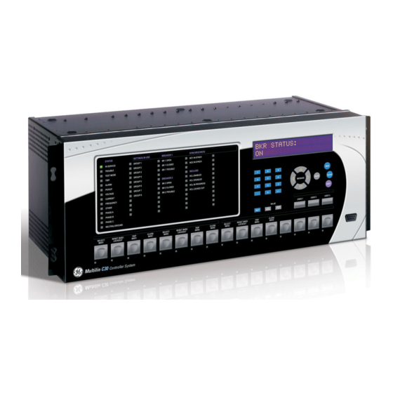
GE C30 Instruction Manual (456 pages)
UR series
Brand:
GE
| Category:
Controller
| Size: 10 MB
Table of Contents
Table of Contents
3
1 Getting Started
13
Important Procedures
13
Cautions and Warnings
13
Inspection Checklist
14
Overview
15
Introduction to the Ur
15
Hardware Architecture
15
Ur Software Architecture
17
Important Concepts
17
Enervista Ur Setup Software
18
Requirements
18
Installation
18
Configuring the C30 for Software Access
19
Using the Quick Connect Feature
22
Connecting to the C30 Relay
28
Ur Hardware
29
Mounting and Wiring
29
Communications
29
Faceplate Display
29
Using the Relay
30
Faceplate Keypad
30
Menu Navigation
30
Menu Hierarchy
30
Relay Activation
30
Relay Passwords
31
Flexlogic Customization
31
Commissioning
32
2 Product Description
33
Introduction
33
Overview
33
Ordering
33
Replacement Modules
38
Specifications
40
User-Programmable Elements
40
Monitoring
41
Inputs
41
Power Supply
42
Outputs
42
Communications
44
Inter-Relay Communications
44
Environmental
45
Type Tests
46
Production Tests
46
Approvals
47
Maintenance
47
3 Hardware
49
Description
49
Panel Cutout
49
Module Withdrawal and Insertion
54
Rear Terminal Layout
56
Wiring
57
Typical Wiring
57
Dielectric Strength
58
Control Power
58
Process Bus Modules
59
Contact Inputs and Outputs
59
Transducer Inputs/Outputs
67
Rs232 Faceplate Port
67
Cpu Communication Ports
68
Irig-B
70
Direct Input/Output Communications
71
Description
71
Fiber: Led and Eled Transmitters
73
Fiber-Laser Transmitters
73
Interface
74
Rs422 Interface
77
Rs422 and Fiber Interface
79
And Fiber Interface
79
Ieee C37.94 Interface
80
C37.94Sm Interface
83
4 Human Interfaces
87
Enervista Ur Setup Software Interface
87
Introduction
87
Creating a Site List
87
Enervista Ur Setup Overview
87
Enervista Ur Setup Main Window
89
Extended Enervista Ur Setup Features
90
Settings Templates
90
Securing and Locking Flexlogic Equations
94
Settings File Traceability
96
Faceplate Interface
99
Faceplate
99
Led Indicators
100
Custom Labeling of Leds
103
Display
109
Keypad
109
Breaker Control
109
Menus
110
Changing Settings
112
5 Settings
113
Overview
117
Settings Menu
117
Introduction to Elements
120
Product Setup
121
Security
121
Cybersentry Security
125
Display Properties
132
Clear Relay Records
133
Communications
134
Modbus User Map
160
Real Time Clock
160
Oscillography
165
Data Logger
167
User-Programmable Leds
168
User-Programmable Self Tests
171
Control Pushbuttons
173
User-Programmable Pushbuttons
174
Flex State Parameters
179
User-Definable Displays
180
Direct Inputs and Outputs
183
Teleprotection
190
Installation
190
Remote Resources Configuration
192
System Setup
193
Breakers
193
Disconnect Switches
197
Flexlogic
200
Introduction to Flexlogic
200
Flexlogic Rules
206
Flexlogic Evaluation
207
Flexlogic Example
207
Flexlogic Equation Editor
212
Flexlogic Timers
212
Flexelements
213
Non-Volatile Latches
217
Control Elements
218
Overview
218
Selector Switch
218
Digital Elements
224
Digital Counters
227
8-Bit Switches
229
Pid Regulator
231
Inputs and Outputs
234
Contact Inputs
234
Virtual Inputs
236
Contact Outputs
237
Virtual Outputs
239
Remote Devices
240
Remote Inputs
241
Remote Double-Point Status Inputs
242
Remote Outputs
242
Resetting
243
Direct Inputs/Outputs
244
Teleprotection Inputs and Outputs
248
Iec 61850 Goose Analogs
250
Iec 61850 Goose Integers
251
Transducer Inputs and Outputs
252
Dcma Inputs
252
Rtd Inputs
253
Dcma Outputs
255
Testing
257
Test Mode
257
Force Contact Inputs
258
Force Contact Outputs
259
6 Actual Values
261
Overview
261
Actual Values Menu
261
Status
261
Contact Inputs
263
Virtual Inputs
263
Remote Inputs
263
Remote Double-Point Status Inputs
264
Teleprotection Inputs
264
Contact Outputs
264
Virtual Outputs
265
Remote Devices
265
Selector Switches
266
Digital Counters
266
Flex States
266
Ethernet
266
Real Time Clock Synchronizing
267
Direct Inputs
268
Iec 61850 Goose Integers
269
Egd Protocol Status
269
Teleprotection Channel Tests
270
Remaining Connection Status
270
Metering
271
Flexelements
271
Iec 61580 Goose Analog Values
271
Transducer Inputs/Outputs
271
Records
273
Event Records
273
Oscillography
273
Data Logger
274
Product Information
275
Model Information
275
Firmware Revisions
275
7 Commands and Targets
277
Commands
277
Commands Menu
277
Virtual Inputs
277
Clear Records
277
Set Date and Time
277
Relay Maintenance
279
Security
279
Targets Menu
281
Target Messages
281
Relay Self-Tests
281
8 Security
289
User Accounts
289
Overview
289
Enabling the Security Management System
289
Adding a New User
289
Modifying User Privileges
290
Password Requirements
291
Cybersentry
292
Overview
292
Security Menu
294
Parameter Lists
299
Flexanalog Items
299
A.1.1 Flexanalog Items
299
Flexinteger Items
302
A.1.2 Flexinteger Items
302
Modbus Rtu Protocol
303
Introduction
303
Physical Layer
303
Data Link Layer
303
B.1.1 Introduction
303
Algorithm
304
B.1.4 Crc-16 Algorithm
304
Modbus Function Codes
305
Supported Function Codes
305
Read Actual Values or Settings (Function Code 03/04H
305
Execute Operation (Function Code 05H
306
Store Single Setting (Function Code 06H
306
Store Multiple Settings (Function Code 10H
307
Exception Responses
307
File Transfers
308
Obtaining Relay Files Via Modbus
308
Modbus Password Operation
309
Memory Mapping
311
Modbus Memory Map
311
Data Formats
357
B.4.2 Data Formats
357
Iec 61850 Communications
393
Overview
393
Introduction
393
Communication Profiles
393
C.1.1 Introduction
393
Server Data Organization
394
Overview
394
Ggio1: Digital Status Values
394
Ggio2: Digital Control Values
394
Ggio3: Digital Status and Analog Values from Received Goose Data
394
Ggio4: Generic Analog Measured Values
394
C.2.1 Overview
394
Mmxu: Analog Measured Values
395
Protection and Other Logical Nodes
395
Advertisement
GE C30 Instruction Manual (416 pages)
Controller System
Brand:
GE
| Category:
Controller
| Size: 14 MB
Table of Contents
Table of Contents
3
1 Introduction
9
Safety Symbols and Definitions
9
General Cautions and Warnings
9
For Further Assistance
10
2 Product Description
13
Security
14
Order Codes
18
Order Codes with Enhanced CT/VT Modules
18
Order Codes with Process Bus Modules
21
Replacement Modules
25
Signal Processing
27
UR Signal Processing
27
Specifications
29
Protection Elements
30
User-Programmable Elements
30
Monitoring
31
Inputs
32
Power Supply
33
Outputs
34
Communication Protocols
36
Inter-Relay Communications
37
Cybersentry Security
38
Environmental
38
Type Tests
39
Production Tests
40
Approvals
40
Maintenance
40
3 Installation
41
Unpack and Inspect
41
Panel Cutouts
42
Horizontal Units
42
Vertical Units
43
Rear Terminal Layout
48
Wiring
49
Typical Wiring
49
Dielectric Strength
50
Control Power
50
Process Bus Modules
51
Contact Inputs and Outputs
51
Transducer Inputs and Outputs
59
RS232 Faceplate Port
61
CPU Communication Ports
62
Irig-B
64
Direct Input and Output Communications
65
Description
65
Fiber: LED and ELED Transmitters
68
Fiber Laser Transmitters
68
Interface
69
RS422 Interface
73
RS422 and Fiber Interface
75
And Fiber Interface
76
IEEE C37.94 Interface
76
C37.94SM Interface
79
Activate Relay
82
Install Software
83
Enervista Communication Overview
83
System Requirements
84
Install Software
85
Add Device to Software
86
Set IP Address in UR
86
Configure Serial Connection
92
Configure Ethernet Connection
93
Configure Modem Connection
95
Automatic Discovery of UR Devices
95
Connect to the C30
96
Connect to the C30 in Enervista
96
Use Quick Connect Via the Front Panel RS232 Port
97
Use Quick Connect Via a Rear Ethernet Port
98
Set up Cybersentry and Change Default Password
98
Import Settings
99
4 Interfaces
101
Enervista Software Interface
101
Introduction
101
Settings Files
101
Event Viewing
102
File Support
102
Enervista Main Window
103
Protection Summary Window
104
Settings Templates
105
Secure and Lock Flexlogic Equations
109
Settings File Traceability
112
Front Panel Interface
115
Front Panel Display
115
Front Panel Keypad
116
Menu Navigation
116
Menu Hierarchy
116
Changing Settings
117
Faceplate
119
LED Indicators
120
Custom LED Labeling
123
Breaker Control
128
Change Passwords
129
Invalid Password Entry
130
Logic Diagrams
131
Flexlogic Design and Monitoring Using Engineer
132
Design Logic
134
Send File to and from Device
144
Monitor Logic
145
View Front Panel and Print Labels
146
Generate Connectivity Report
147
Preferences
147
Toolbars
151
5 Settings
157
Settings Menu
157
Overview
159
Introduction to Elements
159
Product Setup
160
Security
160
Display Properties
178
Clear Relay Records
179
Communications
180
Modbus User Map
245
Real-Time Clock
245
Oscillography
250
Data Logger
252
User-Programmable Leds
253
User-Programmable Self-Tests
257
Control Pushbuttons
257
User-Programmable Pushbuttons
259
Flex State Parameters
264
User-Definable Displays
265
Direct Inputs and Outputs
267
Teleprotection
273
Installation
274
Remote Resources
274
Remote Resources Configuration
274
System Setup
276
Breakers
276
Switches
280
Flexlogic
283
Flexlogic Operands
283
Flexlogic Rules
291
Flexlogic Evaluation
291
Flexlogic Example
291
Flexlogic Equation Editor
296
Flexlogic Timers
296
Flexelements
296
Non-Volatile Latches
301
Control Elements
302
Overview
302
Trip Bus
302
Selector Switch
304
Digital Elements
310
Digital Counters
313
8-Bit Switches
315
PID Regulator
316
Inputs/Outputs
319
Contact Inputs
319
Virtual Inputs
321
Contact Outputs
322
Virtual Outputs
326
Resetting
326
Direct Inputs and Outputs
326
Teleprotection
330
Transducer Inputs/Outputs
332
Dcma Inputs
332
RTD Inputs
333
Dcma Outputs
334
Testing
336
Test Mode Function
336
Test Mode Forcing
337
Force Contact Inputs
337
Force Contact Outputs
338
6 Actual Values
340
Front Panel
340
Status
341
Contact Inputs
341
Virtual Inputs
341
Rxgoose Boolean Inputs
342
Rxgoose DPS Inputs
342
Teleprotection Inputs
342
Contact Outputs
342
Virtual Outputs
343
Rxgoose Status
343
Rxgoose Statistics
343
Digital Counters
344
Selector Switches
344
Flex States
344
Ethernet
344
Real Time Clock Synchronizing
345
Direct Inputs
345
Direct Devices Status
346
EGD Protocol Status
346
Teleprotection Channel Tests
347
Remaining Connection Status
347
Parallel Redundancy Protocol (PRP)
348
Txgoose Status
348
Metering
349
Flexelements
349
Rxgoose Analogs
349
Transducer Inputs and Outputs
350
Records
350
Event Records
350
Oscillography
351
Data Logger
351
Product Information
352
Model Information
352
Firmware Revisions
352
GE C30 Instruction Manual (488 pages)
Controller System
Brand:
GE
| Category:
Control Systems
| Size: 18 MB
Table of Contents
Table of Contents
3
Introduction
9
For Further Assistance
10
Product
13
Description
14
2.2 Security
18
Order Codes
18
Order Codes with Process Bus Modules
21
Replacement Modules
24
Signal Processing
27
Specifications
29
Monitoring
31
Power Supply
33
Communication Protocols
35
Inter-Relay Communications
36
Cybersentry Security
38
Type Tests
39
Approvals
40
Installation
41
Wiring
52
Dielectric Strength
53
Process Bus Modules
54
Transducer Inputs and Outputs
66
RS232 Port
68
CPU Communication Ports
69
Irig-B
71
Direct Input and Output Communications
72
Fiber: LED and ELED Transmitters
75
G.703 Interface
76
RS422 Interface
80
RS422 and Fiber Interface
82
G.703 and Fiber Interface
83
C37.94SM Interface
86
Activate Relay
89
Install Software
90
System Requirements
91
Install Software
92
Add Device to Software
93
Configure Serial Connection
98
Configure Ethernet Connection
99
Configure Modem Connection
101
Connect to the C30
102
Use Quick Connect Via the Front Panel RS232 Port
103
Use Quick Connect Via a Rear Ethernet Port
104
Set up Cybersentry and Change Default Password
105
3.10 Import Settings
106
Connect to D400 Gateway
106
Setting Files
107
5.2 Overview
109
Introduction
109
Event Viewing
110
Enervista Main Window
111
Protection Summary Window
112
Settings Templates
113
Secure and Lock Flexlogic Equations
117
Settings File Traceability
120
Front Panel Interface
122
Front Panel Display
125
Front Panel Navigation Keys
146
LED Indicators
148
Front Panel Labelling
151
Menu Navigation
158
Change Settings
160
View Actual Values
165
Breaker Control
166
Change Passwords
167
Invalid Password Entry
169
4.3 Logic Diagrams
170
Flexlogic Design Using Engineer
170
Design Logic
172
Send File to and from Device
182
Monitor Logic
183
View Front Panel and Print Labels
184
Generate Connectivity Report
185
Toolbars
189
Overview
197
Product Setup
198
Display Properties
216
Graphical Front Panel
217
Clear Relay Records
229
Communications
230
Modbus User Map
297
Real-Time Clock
298
Oscillography
302
Data Logger
305
User-Programmable Leds
306
User-Programmable Self-Tests
310
Control Pushbuttons
311
User-Programmable Pushbuttons
312
Flex State Parameters
318
User-Definable Displays
319
Direct Inputs and Outputs
321
Teleprotection
327
Installation
328
5.4 Remote Resources
330
System Setup
330
Switches
335
Flexlogic
340
Flexlogic Rules
349
Flexlogic Example
350
Flexlogic Equation Editor
355
Non-Volatile Latches
359
Control Elements
360
Selector Switch
362
Digital Elements
368
Digital Counters
371
Bit Switches
373
PID Regulator
374
Inputs/Outputs
377
Virtual Inputs
379
Contact Outputs
380
Virtual Outputs
384
Direct Inputs and Outputs
385
Teleprotection
389
Transducer Inputs/Outputs
390
RTD Inputs
391
Dcma Outputs
392
Testing
394
Test Mode Forcing
395
Force Contact Outputs
396
Actual Values Menu
397
Front Panel
398
Status
399
Metering
407
Records
408
Oscillography
410
Product Information
411
Advertisement
GE C30 Communications Manual (532 pages)
Universal Relay Family
Brand:
GE
| Category:
Relays
| Size: 3 MB
Table of Contents
Table of Contents
3
1 Introduction
7
Products
7
Features Per Product
7
Communication Ports
20
Safety Symbols and Definitions
20
For Further Assistance
20
Modbus
21
2 Modbus Communication
21
Modbus RTU Protocol
21
Introduction
21
Configuration
21
Physical Layer
21
Data Link Layer
22
Modbus RTU CRC-16 Algorithm
23
Modbus Function Codes
24
Supported Function Codes
24
Read Actual Values or Settings (Function Code 03/04H)
24
Execute Operation (Function Code 05H)
25
Store Single Setting (Function Code 06H)
25
Store Multiple Settings (Function Code 10H)
26
Exception Responses
26
File Transfers
27
Obtaining Relay Files Using Modbus
27
Memory Map
32
Modbus Memory Map
32
6 Iec 60870-5-104
80
Communication
81
Data Formats
204
3 Iec 61850 Communication
239
Overview
239
Introduction
239
Abstract Communication Service Interface (ASCI)
241
Datasets
244
Txgoose
245
Rxgoose
247
Reports
248
Commands
250
Substation Configuration Language (SCL)
250
Configuring the UR Using SCL
256
Merge SCL File
261
Configurable Logical Devices
262
Protocol Implementation Conformance Statement (PICS)
262
Basic Conformance Statement
262
ACSI Conformance Statement
263
ACSI Basic Conformance Statement
263
ACSI Models Conformance Statement
263
ACSI Services Conformance Statement
265
Model Implementation Conformance Statement (MICS)
267
Master (Root) Logical Device
268
Protection (Prot) Logical Device
275
Control (Ctrl) Logical Device
354
System Logical Device
389
Meter Logical Device
410
General (Gen) Logical Device
431
GE Namespace
447
Enumerations
462
SCL Implementation Conformance Statement (SICS)
463
PIXIT Conformance Statement
465
TICS Conformance Statement
470
SCL Logging
472
Overview of Process
472
SCL File Storage on UR
473
Generation of CID Files
473
Schema Version Used by Ur/Enervista
473
CID File Processing Steps
473
SCL Log File Format and Examples
473
Troubleshooting Log File Errors
475
G2 Implementation Model for GOOSE Configuration Via SCL
475
Introduction
475
Configuration Process
476
Configuration Process with IED Setup Tool
478
IED Capability Description (ICD) File
478
Instantiated IED Capability Description (IID) File
482
Configured IED Description (CID) File
482
Sample SCL Files
484
Annex - Optional Intermediate GOOSE Reception Objects
489
E3-2.0 Implementation Model for GOOSE Configuration Via SCL
492
Introduction
492
Workflow
492
ICD Files
493
CID Files
494
IID Files
495
GE C30 Communications Manual (526 pages)
UR Family
Brand:
GE
| Category:
Controller
| Size: 3 MB
Table of Contents
Table of Contents
3
1 Introduction
7
Products
7
Features Per Product
7
Communication Ports
20
Safety Symbols and Definitions
20
For Further Assistance
20
Modbus
21
2 Modbus Communication
21
Modbus RTU Protocol
21
Introduction
21
Configuration
21
Physical Layer
21
Data Link Layer
22
Modbus RTU CRC-16 Algorithm
23
Modbus Function Codes
24
Supported Function Codes
24
Read Actual Values or Settings (Function Code 03/04H)
24
Execute Operation (Function Code 05H)
25
Store Single Setting (Function Code 06H)
25
Store Multiple Settings (Function Code 10H)
26
Exception Responses
26
File Transfers
27
Obtaining Relay Files Using Modbus
27
Memory Map
32
Modbus Memory Map
32
6 Iec 60870-5-104
80
Communication
81
Data Formats
203
3 Iec 61850 Communication
239
Overview
239
Introduction
239
Abstract Communication Service Interface (ASCI)
241
Datasets
244
Txgoose
245
Rxgoose
247
Reports
248
Commands
250
Substation Configuration Language (SCL)
250
Configuring the UR Using SCL
256
Merge SCL File
261
Configurable Logical Devices
262
Protocol Implementation Conformance Statement (PICS)
262
Basic Conformance Statement
262
ACSI Conformance Statement
263
ACSI Basic Conformance Statement
263
ACSI Models Conformance Statement
263
ACSI Services Conformance Statement
265
Model Implementation Conformance Statement (MICS)
267
Master (Root) Logical Device
268
Protection (Prot) Logical Device
275
Control (Ctrl) Logical Device
351
System Logical Device
385
Meter Logical Device
406
General (Gen) Logical Device
426
GE Namespace
442
Enumerations
457
SCL Implementation Conformance Statement (SICS)
458
PIXIT Conformance Statement
460
TICS Conformance Statement
465
SCL Logging
467
Overview of Process
467
SCL File Storage on UR
468
Generation of CID Files
468
Schema Version Used by Ur/Enervista
468
CID File Processing Steps
468
SCL Log File Format and Examples
468
Troubleshooting Log File Errors
470
G2 Implementation Model for GOOSE Configuration Via SCL
470
Introduction
470
Configuration Process
471
Configuration Process with IED Setup Tool
473
IED Capability Description (ICD) File
473
Instantiated IED Capability Description (IID) File
477
Configured IED Description (CID) File
477
Sample SCL Files
479
Annex - Optional Intermediate GOOSE Reception Objects
484
E3-2.0 Implementation Model for GOOSE Configuration Via SCL
487
Introduction
487
Workflow
487
ICD Files
488
CID Files
489
IID Files
490
GE C30 Instruction Manual (342 pages)
Controller System
Brand:
GE
| Category:
Controller
| Size: 7 MB
Table of Contents
Table of Contents
3
1 Introduction
9
Safety Symbols and Definitions
9
General Cautions and Warnings
9
For Further Assistance
10
2 Product Description
11
Security
12
Order Codes
15
Order Codes with Enhanced CT/VT Modules
16
Order Codes with Process Bus Modules
18
Replacement Modules
21
Specifications
23
User-Programmable Elements
23
Monitoring
24
Inputs
25
Power Supply
26
Outputs
27
Communication Protocols
29
Inter-Relay Communications
30
Environmental
31
Type Tests
32
Production Tests
32
Approvals
33
Maintenance
33
3 Installation
35
Unpack and Inspect
35
Panel Cutouts
36
Horizontal Units
36
Vertical Units
37
Rear Terminal Layout
41
Wiring
43
Typical Wiring
43
Dielectric Strength
44
Control Power
44
Process Bus Modules
45
Contact Inputs and Outputs
45
Transducer Inputs and Outputs
53
RS232 Faceplate Port
55
CPU Communication Ports
55
Irig-B
57
Direct Input and Output Communications
58
Description
58
Fiber: LED and ELED Transmitters
60
Fiber Laser Transmitters
60
Interface
61
RS422 Interface
65
RS422 and Fiber Interface
67
And Fiber Interface
67
IEEE C37.94 Interface
68
C37.94SM Interface
71
Activate Relay
74
Install Software
75
Enervista Communication Overview
75
System Requirements
76
Install Software
76
Configure the C30 for Software Access
77
Configure Serial Communication
78
Configure Ethernet Communication
79
Automatic Discovery of UR Devices
80
Connect to the C30
80
Connect to the C30 in Enervista
80
Use Quick Connect Via the Front Panel RS232 Port
81
Use Quick Connect Via a Rear Ethernet Port
82
Set up Cybersentry and Change Default Password
87
4 Interfaces
89
Enervista Software Interface
89
Introduction
89
Settings Files
89
Event Viewing
90
File Support
90
Enervista Main Window
90
Settings Templates
91
Secure and Lock Flexlogic Equations
96
Settings File Traceability
98
Front Panel Interface
100
Front Panel Display
100
Front Panel Keypad
100
Menu Navigation
101
Menu Hierarchy
101
Changing Settings
102
Faceplate
103
LED Indicators
105
Custom LED Labeling
108
Breaker Control
114
Change Passwords
115
Invalid Password Entry
116
Logic Diagrams
117
5 Settings
119
Settings Menu
119
SETTINGS 5.1 Settings Menu
119
Overview
121
Introduction to Elements
121
Product Setup
122
Security
122
Display Properties
140
Clear Relay Records
141
Communications
142
Modbus User Map
195
Real-Time Clock
196
Oscillography
200
Data Logger
202
User-Programmable Leds
203
User-Programmable Self-Tests
207
Control Pushbuttons
207
User-Programmable Pushbuttons
209
Flex State Parameters
214
User-Definable Displays
215
Direct Inputs and Outputs
217
Teleprotection
224
Installation
225
Remote Resources
225
Remote Resources Configuration
225
System Setup
226
Breakers
226
Flexlogic
230
Flexlogic Operands
234
Flexlogic Rules
241
Flexlogic Evaluation
242
Flexlogic Example
242
Flexlogic Equation Editor
247
Flexlogic Timers
247
Flexelements
247
Non-Volatile Latches
251
Control Elements
252
Overview
252
Selector Switch
252
Digital Elements
258
Digital Counters
260
8-Bit Switches
262
PID Regulator
263
Inputs/Outputs
266
Contact Inputs
266
Virtual Inputs
268
Contact Outputs
269
Virtual Outputs
272
Resetting
272
Direct Inputs and Outputs
273
Transducer Inputs/Outputs
278
Dcma Inputs
278
RTD Inputs
279
Dcma Outputs
280
Testing
282
Test Mode Function
282
Test Mode Forcing
283
Force Contact Inputs
283
Force Contact Outputs
284
6 Actual Values
285
Actual Values Menu
285
Status
286
Contact Inputs
286
Virtual Inputs
287
Rxgoose Boolean Inputs
287
Rxgoose DPS Inputs
287
Teleprotection Inputs
288
Contact Outputs
288
Virtual Outputs
288
Rxgoose Status
288
Rxgoose Statistics
289
Digital Counters
289
Selector Switches
290
Flex States
290
Ethernet
290
Real Time Clock Synchronizing
290
Direct Inputs
291
Direct Devices Status
292
EGD Protocol Status
292
Teleprotection Channel Tests
292
Remaining Connection Status
293
Parallel Redundancy Protocol (PRP)
293
Metering
294
Flexelements
294
Rxgoose Analogs
294
Transducer Inputs and Outputs
295
Event Records
295
Oscillography
295
Product Information
296
Model Information
296
Firmware Revisions
297
Advertisement
Related Products
GE C60
GE LOGIQ C3 Premium
GE CG740
GE CA10
GE CA16DJ
GE CGS985SET
GE Current Lumination ISC Series
GE CGS750P2MS1
GE CHS995SELSS
GE CEB1590SS3SS
GE Categories
Refrigerator
Ranges
Microwave Oven
Dishwasher
Air Conditioner
More GE Manuals
Login
Sign In
OR
Sign in with Facebook
Sign in with Google
Upload manual
Upload from disk
Upload from URL