Sign In
Upload
Manuals
Brands
EURA DRIVES Manuals
DC Drives
E800-0004 T3
EURA DRIVES E800-0004 T3 Manuals
Manuals and User Guides for EURA DRIVES E800-0004 T3. We have
1
EURA DRIVES E800-0004 T3 manual available for free PDF download: Safety Instructions, Installation And Operating Manual
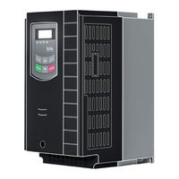
EURA DRIVES E800-0004 T3 Safety Instructions, Installation And Operating Manual (69 pages)
0,2kW – 110kW (IP20)
Brand:
EURA DRIVES
| Category:
DC Drives
| Size: 1.81 MB
Table of Contents
Table of Contents
2
Index
2
Common Installation
3
Common
4
Specified Application of Frequency Inverters
4
Observe Specific Standards and Rules
4
Handling, Transportation and Storage
5
Installation of the Inverter
5
Long Motor Leads
6
Electrical Wiring of Frequency Inverters
6
Insulation Testing
7
Potential Equalization
7
Braking Resistors
8
Differential Current Braker (FI)
8
Basic Rules for Reliable and Safe Operation
9
Inverter Protection-Functions
9
Measurements on Inverter Input and Output
10
Power-Grid Specification
10
Power Supply – Short Circuit Capability
10
EMC: Basics and Recommendations for Installation
11
EMC - Adequate Installation
11
Twist All Unshielded Cables
11
Product Data / Product Range
13
Product Naming Convention
13
Options Identifier
13
Nameplate
13
Mechanical Construction
14
Technical Data – Inverter Series E800
16
Product Range - Framesize
17
Inverter 400V – 3 Phase
17
Inverter 230V – 1 Phase
17
Inverter 230V – 3 Phase
17
Maintenance and Service
18
Mounting in Cabinet
18
Inverter Mounting
18
Electrical Connection of E800 Inverters
19
230V Singlephase
19
Power Terminals
19
230V Threephase
19
2014 EURADRIVES EUROPE Gmbh
19
400V Threephase
20
2014 EURADRIVES EUROPE Gmbh
20
400V Threephase above 30 Kw
21
Brake Resistor
21
2014 EURADRIVES EUROPE Gmbh
21
Recommended Cable Cross Sections, Fuses
22
Earth/Ground Connection
22
Minimum Earth/Ground Wiring Cross Section – for Terminal Connection
22
2014 EURADRIVES EUROPE Gmbh
22
2014 EURADRIVES EUROPE Gmbh
23
Inverter Size C3 – C6
23
Control Terminals – Control Board
23
Control Terminal Function and Factory Default Configuration
24
2014 EURADRIVES EUROPE Gmbh
24
Sample Set-Up for Inverter, 400V - Framesize
25
2014 EURADRIVES EUROPE Gmbh
25
Control-Board: Hardware and I/O Channel Configuration
26
Digital Input Channels
26
Analogue Input Channels
27
Digital Output Channels
28
Analogue Output Channels
28
Control-Board Inverter
29
Digital Output Channels:
31
Analogue Output Channels:
31
Motor Protection with PTC/KLIXON
31
7-Segment Display:
32
Status LED
32
Keys and Functions
32
Operating Panel
32
Display of Function Parameters and Error Codes
33
Remote Operating Panel
33
Parametrization
34
Selection of Parameters, Modification and Saving
34
Parameter Types
34
Parameter Group 100: Basic Parameters
35
Dead Time During Reversion (Sec.)
36
Reverse Operation Disable
36
Cut-Off Frequency Window A,B (Hz)
37
Jog Frequency (Hz)
37
Cut-Off Frequency A,B (Hz)
37
Display Configuration:
37
Transmission Ratio
38
Pulley Diameter
38
Slip Compensation in V/Hz Mode
39
Lineare Increase
39
Quadratic Increase
39
Power Supply Voltage Compensation
40
BOOST Intensity (%)
40
PWM Frequency
40
BOOST-Kneefrequency (Hz)
40
START / STOP / Running Direction
41
Rotation Direction Preset
41
Selection of Speed Reference Sources
41
Parameter Group 200: Inverter Control
41
Two / Three Wire Control for START – STOP - Rotation
44
“STOP” Mode Selection
45
Status Memory with
45
Autostart after Power-Down
45
Inverter-Error AUTO-RESET
45
Function Mapping for Digital Output Channels
46
Parameter Group 300: Digital I/O Configuration
46
Activation and Configuration of the "S" Shaped Ramp
47
Frequency Threshold Setting
47
Current Threshold
47
Function Mapping for Digital Input Channels
48
Table of Digital Input Functions
48
Fixed-Frequencies Selection – Table 300-1
49
Accel./Decel. Ramp Selection - Table 300-2
49
Parameter Group 400: Analogue I/O Channel Configuration
50
Configuration of Analogue Speed Reference Channels
50
Non-Linear Characteristic for Analogue Channels
52
Analogue Output Configuration
53
Programming of the Individual Fixed-Frequencies
54
Parameter Group 500: Fixed-Frequency, Automatic Cycling Frequencies
54
DC-Brake Function Parameters
55
Parameter for DC-Brake Control
55
Current- Voltage Limiting Functions
55
Parameter Group 600: DC-Bake Control / Aux. Functions
55
Brake Chopper Control (Internal Brake Chopper)
56
DC-Voltage Control
56
Errorcodes (on Display)
57
Parameter Group 700: Error Handling and Protection Functions
57
Fan Control Mode
58
Inverter/Motor Over-Load Protection
58
Fault History
59
Error: Event Counter
59
Protection Functions – Configuration
59
Delay for Inverter Error Trip
59
Idling Detection (Message Via Digital Output – Function Code 20)
60
Parameter Group 800: Autotuning – Motor Data Programming
61
Parameter Group 900: RS485 Hardware and Interface Parameters
63
Parameter Group A00: PID Controller Parameter
64
PID Controller Parameter Setting
66
Emergency Functions
66
E800 Diagnosis
67
Digital Input Status Monitoring
67
Analogue Input Value Check
67
Digital Output Stimulation
67
Advertisement
Advertisement
Related Products
EURA DRIVES E800-0002 S2
EURA DRIVES E800-0004 S2
EURA DRIVES E800-0002 T3
EURA DRIVES E800-0005 T3
EURA DRIVES E800-0007 S2
EURA DRIVES E800-0007 T3
EURA DRIVES E800-0015 T3
EURA DRIVES E800-0055 T3
EURA DRIVES E800-0075 T3
EURA DRIVES E800-0040 T3
EURA DRIVES Categories
Inverter
DC Drives
More EURA DRIVES Manuals
Login
Sign In
OR
Sign in with Facebook
Sign in with Google
Upload manual
Upload from disk
Upload from URL