Sign In
Upload
Manuals
Brands
Danfoss Manuals
Media Converter
VACON 1000
Danfoss VACON 1000 Manuals
Manuals and User Guides for Danfoss VACON 1000. We have
3
Danfoss VACON 1000 manuals available for free PDF download: Operating Manual
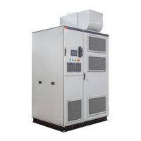
Danfoss VACON 1000 Operating Manual (194 pages)
Brand:
Danfoss
| Category:
Industrial Equipment
| Size: 16 MB
Table of Contents
Table of Contents
3
Introduction
9
Purpose of this Operating Guide
9
Additional Resources
9
Version History
9
Recommended Disposal
9
Safety
11
Safety Symbols
11
Qualified Personnel
11
Safety Precautions
12
Product Overview
16
Product Characteristics
16
Applications
16
System Hardware
17
Control Cabinet
18
Controls and Indicators
20
Power Cell Cabinet
21
Transformer Cabinet
23
Junction Cabinet
24
Start-Up Cabinet
25
Output Filter Cabinet
27
Bypass Cabinet
28
Manual Bypass Cabinet
29
Automatic Bypass Cabinet
31
Synchronous Transfer Cabinet
33
System Operation
35
Main Circuit
35
Power Cells
37
Control System
38
Type Code Description
40
Available Options
41
Cell Bypass
44
Cell Redundancy
44
Cabinet Bypass
44
Input Devices
44
Output Devices
44
Cabinet Options
44
Mechanical Options
44
Environment Options
46
Engineered Options
46
PC Tools for VACON® 1000
47
Receiving the Delivery
48
Checking the Delivery
48
Contents of the Delivery
48
Storage
49
Lifting and Moving the Drive
50
Guidelines for Lifting and Moving the Drive
50
Lifting the Standalone Cabinets
50
Lifting the Line-Up Cabinets
52
Moving the Cabinets with a Forklift or Roller Tubes
53
Mechanical Installation
55
Operating Environment
55
Cabinet Installation Guidelines
55
Foundation for the Drive
56
Attaching the Cabinets
56
Mounting the Cabinets
57
Installing the Power Cells
58
Dimensions of the Enclosed Drive
60
Cooling and Free Space Around the Enclosed Drive
60
Air Ducting Guidelines
61
Fan Installation
62
Installing the Fans
62
Installing Fans with Noise-Shielding Hood
64
Installing Fans with Air Hood
65
Electrical House Installation
66
Electrical Installation
67
The Main Circuit
67
Main Circuit Breaker and Fuses
67
Galvanic Isolation between the MV and LV Sections
67
Terminals
67
Terminal Locations in the Standalone Cabinet
67
Terminal Locations in the Line-Up Cabinet
68
Cable Entry and Termination
69
Power Cable Entry of Standalone Cabinet
69
Power Cable Entry of Line-Up Cabinet
70
Power Cable Termination
71
Control Cable Entry
71
Grounding
73
Power Cable Selection
74
Additional Instructions for Cable Installation
74
Control Wiring
75
Control Cable Selection
75
Control Power Wiring
75
Control Circuit Wiring
76
Application Wiring Example
79
PLC Configuration
80
PLC Basic Configuration
80
Options and Customized Designs
81
Analog I/O Setting
82
Hardware Settings
82
Software Settings
83
Human-Machine Interface
84
The VACON® 1000 HMI
84
HMI Homepage
84
System Status
85
Dashboard
85
Single-Line Diagram
85
Control Panel
85
Status
86
Power Cell
86
Cooling Fan
87
Graphs & Reports
87
Setup & Service
88
Operation Mode
89
Motor Parameter
89
Functions
90
Protections
90
PID Setup
90
System Configuration
91
Events
91
Warning & Fault
91
Event Log
92
Administration
93
Tool Settings
94
Language
94
Software Version
94
HMI Set
94
Commissioning
96
Safety Checks before Starting the Commissioning
96
Personnel Requirements
97
Commissioning the Drive
97
Basic Job Information
98
Before Power-Up Checklist
98
Control and Auxiliary Power Commissioning Checklist
101
Medium-Voltage Power Commissioning Checklist
102
Commissioning Procedures
103
Dielectric Withstand Test
103
Testing Input and Output Together
103
Testing Input and Output Separately
104
Dehumidification Process
104
VACON® 1000 with Options +QT02 and +MHEH/+MHET/+MHTH
105
VACON® 1000 Without Options +QT02 and +MHEH/+MHET/+MHTH
105
VACON® 1000 in U/F Operation
105
Dehumidification Process Operation Times
105
MCB and Drive Interlock Signal Test
105
Transformer Overtemperature Protection Test
105
V/F Control Test Without Motor
106
Test with Motor (no Load)
107
DCS Test
108
Test with Load
108
Commissioning Report
109
Operating the Drive
109
Powering the Drive
109
Starting the Drive
110
Stopping the Drive
111
Powering off the Drive
111
Interlocking System
112
Electromagnetic Interlocking System
112
Mechanical Interlocking System
112
Maintenance
114
Safety
114
Standard Maintenance Process
115
Daily and Weekly Maintenance
115
Preventive Maintenance Recommendations
116
Replacing the Air Filters
120
Air Filters of Standalone Cabinets
120
Air Filters of Transformer and Power Cell Cabinets
121
Air Filters of Control Cabinet
122
Replacing the HMI Battery
122
Replacing the Cooling Fans
123
Diagram of the Cooling Fan Replacement
124
UPS Battery
124
Replacing the UPS Battery
124
UPS Battery Maintenance
124
Power Cells
125
Power Cell Maintenance
125
Replacing the Power Cells
127
Diagram of the Power Cell Replacement
128
Reforming the Power Cell Capacitors
128
Reforming with an AC Supply
128
Reforming with a DC Supply
129
Fault Tracing
131
Fault Types
131
Fault Response Configuration
131
Faults and Alarms
131
Troubleshooting
131
Specifications
148
Technical Data
148
Power Ratings and Dimensions
154
IEC Ratings
154
UL Ratings
159
Cabinet Types
168
Internal Cables and Terminals
169
Replacement Fuses
171
Cooling Airflow Ratings
172
IEC Airflow Ratings
172
UL Airflow Ratings
177
BIL Voltage Ratings
187
High-Potential Voltage Ratings
188
Standards
188
Abbreviations
191
Advertisement
Danfoss VACON 1000 Operating Manual (144 pages)
Brand:
Danfoss
| Category:
Media Converter
| Size: 20 MB
Table of Contents
Table of Contents
3
1 Introduction
8
Purpose of this Operating Guide
8
Additional Resources
8
Manual Version
8
Disposal
8
2 Safety
9
Safety Symbols
9
Qualified Personnel
9
Danger and Warnings
9
Cautions and Notices
10
3 Product Overview
13
Product Characteristics
13
Applications
13
System Hardware
14
Control Cabinet
15
Controls and Indicators
17
Power Cell Cabinet
18
Transformer Cabinet
20
Junction Cabinet
21
Start-Up Cabinet
21
Output Filter Cabinet
23
Bypass Cabinet
24
Manual Bypass Cabinet
24
Automatic Bypass Cabinet
25
Synchronous Transfer Cabinet
28
System Operation
29
Main Circuit
29
Power Cells
30
Control System
31
Type Code Description
33
Available Options
34
Cabinet Bypass
36
Input Devices
36
Output Devices
37
Mechanical Options
37
VACON® 1000 PC Tool
37
4 Receiving the Delivery
38
Checking the Delivery
38
Storage
38
Lifting and Moving the Drive
38
Lifting the Standalone Cabinets
38
Lifting the Line-Up Cabinets
40
Using a Forklift
40
5 Mechanical Installation
42
Operating Environment
42
Cabinet Installation
42
Attaching the Cabinets
42
Mounting the Cabinets
44
Installing the Power Cells
44
Dimensions of the Enclosed Drive
45
Cooling and Free Space Around the Enclosed Drive
45
Air Ducting Guidelines
46
6 Electrical Installation
47
The Main Circuit
47
Main Circuit Breaker and Fuses
47
Galvanic Isolation between the MV and LV Sections
47
Terminals
47
Terminal Locations in the Standalone Cabinet
47
Terminal Locations in the Line-Up Cabinet
48
Cable Entry and Termination
49
Power Cable Entry of Standalone Cabinet
49
Power Cable Entry of Line-Up Cabinet
50
Power Cable Termination
51
Control Cable Entry
51
Grounding
53
Power Cable Selection
53
Additional Instructions for Cable Installation
54
Control Wiring
54
Control Cable Selection
54
Control Power Wiring
54
Control Circuit Wiring
55
Application Wiring Example
59
PLC Configuration
60
PLC Basic Configuration
60
Options and Customized Designs
61
7 Human-Machine Interface
63
The VACON® 1000 HMI
63
HMI Homepage
63
System Status
63
Dashboard
64
Single-Line Diagram
64
Control Panel
64
Status
65
Power Cell
65
Cooling Fan
65
Graphs & Reports
65
Setup & Service
66
Operation Mode
67
Motor Parameter
67
Functions
68
Protections
68
PID Setup
68
System Configuration
69
Events
69
Warning & Fault
69
Event Log
70
Administration
71
Tool Settings
72
Language
72
Software Version
72
HMI Set
72
8 Commissioning
74
Safety Checks before Starting the Commissioning
74
Personnel Requirements
74
Commissioning Checks
74
Commissioning Report
76
Operating the Drive
76
Powering the Drive
76
Starting the Drive
76
Stopping the Drive
77
Powering off the Drive
77
Interlocking System
78
Electromagnetic Interlocking System
78
Mechanical Interlocking System
78
9 Maintenance
79
Safety
79
Standard Maintenance Process
80
Maintenance Schedule
80
Daily Maintenance
80
Yearly Maintenance
81
Replacing the Air Filters
82
Air Filters of Standalone Cabinets
82
Air Filters of Transformer and Power Cell Cabinets
83
Air Filters of Control Cabinet
84
Replacing the HMI Battery
84
Replacing the Cooling Fans
85
Diagram of the Cooling Fan Replacement
86
UPS Battery
86
Replacing the UPS Battery
86
UPS Battery Maintenance
86
Power Cells
87
Power Cell Maintenance
87
Replacing the Power Cells
88
Diagram of the Power Cell Replacement
89
Reforming the Power Cell Capacitors
90
Reforming with an AC Supply
90
Reforming with a DC Supply
91
Dielectric Withstand Test
91
Testing Input and Output Together
92
Testing Input and Output Separately
92
10 Fault Tracing
94
Fault Types
94
Fault Response Configuration
94
Faults and Alarms
94
11 Specifications
108
Technical Data
108
Power Ratings and Dimensions
111
IEC Ratings
111
UL Ratings
119
Internal Cables and Terminals
133
Replacement Fuses
135
Standards
136
Abbreviations
140
Danfoss VACON 1000 Operating Manual (98 pages)
Fieldbus Options
Brand:
Danfoss
| Category:
Industrial Equipment
| Size: 4 MB
Table of Contents
Table of Contents
3
Introduction
8
Purpose of this Guide
8
Additional Resources
8
Version History
8
Abbreviations and Acronyms
8
Overview
10
VACON® 1000 Fieldbus Options
10
Modbus RTU/TCP
10
Profibus Dp
11
Canopen
11
Devicenet
12
Profinet I/O
13
Ethernet/Ip
13
Modbus RTU/TCP
14
Cable Selection
14
Programming
14
Ethernet Setting
14
Setting the IP Address with HMI
15
Modbus RTU Configuration
15
Parameters
16
Monitoring Values
17
Parameter Descriptions
17
Parameter Addresses
18
Communications
26
Features
26
Data Addresses in Modbus Messages
26
Supported Modbus Functions
26
Modbus Data Mapping
27
MVD Input Parameters
27
MVD Output Parameters
27
Transformer Temperature
27
Digital Output
27
Digital Input
28
System Alarm/Fault
28
Power Cell Alarm/Fault
32
Advertisement
Advertisement
Related Products
Danfoss Vacon NXP
Danfoss VLT 6000 series
Danfoss VLT 5000 Profibus
Danfoss VLT 3002
Danfoss VLT 3250
Danfoss VLT 2822-2840
Danfoss VLT 2880-82
Danfoss VLT 6006
Danfoss VLT 6062
Danfoss VLT 6275
Danfoss Categories
Controller
DC Drives
Thermostat
Control Unit
Air Compressor
More Danfoss Manuals
Login
Sign In
OR
Sign in with Facebook
Sign in with Google
Upload manual
Upload from disk
Upload from URL