Sign In
Upload
Manuals
Brands
Daikin Manuals
Air Conditioner
FHQ71BUV3B
Daikin FHQ71BUV3B Manuals
Manuals and User Guides for Daikin FHQ71BUV3B. We have
2
Daikin FHQ71BUV3B manuals available for free PDF download: Service Manual
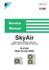
Daikin FHQ71BUV3B Service Manual (390 pages)
Brand:
Daikin
| Category:
Air Conditioner
| Size: 5.61 MB
Table of Contents
Service Manual
1
Table of Contents
3
What Is in this Chapter
3
What Is in this Chapter?
21
Fcq71D
26
Fcq100, 125, 140D
28
Ffq25, 35, 50, 60B
30
Fbq35, 50B
32
Fbq60, 71B
34
Fbq100, 125B
36
Fhq35, 50B
42
Fhq60, 71B
44
Fhq100B
46
Fhq125B
48
Fuq71B
50
Fuq100, 125B
52
Faq71B
54
Faq100B
56
Fdeq71, 100B
58
Fdeq125B
60
What Is in this Chapter?
63
2 Specifications
64
Technical Specifications
71
Electrical Specifications
71
3 Functional Diagrams
73
What Is in this Chapter
73
Indoor Piping
74
Pipe Connection Diameters
76
4 Wiring Diagrams
79
What Is in this Chapter
79
Fcq35, 50, 60B
80
Fcq71, 100, 125B
82
Fcq71, 100, 125, 140D
84
Ffq25, 35, 50, 60B
86
Fbq35, 50, 60B
88
Fbq71B
90
Fbq100, 125B
92
Fdq125, 200, 250B
94
Fhq35, 50, 60B
96
Fhq71, 100, 125B
98
Fuq71, 100, 125B
100
Faq71B
102
Faq100B
104
Fdeq71B
106
Fdeq100B
108
Fdeq125B
110
5 Switch Box Layout
113
What Is in this Chapter
113
Fcq35, 50, 60, 71B
114
Fcq100, 125B
115
Fcq71, 100, 125 140D
116
Ffq25, 35, 50, 60B
117
Fbq35, 50, 60, 71, 100, 125B
118
Fdq125, 200, 250B
119
Fhq35, 50, 60, 71, 100, 125B
120
Fuq71, 100, 125B
121
Faq71B
122
Faq100B
123
Fdeq71, 100, 125B
124
What Is in this Chapter?
125
Fcq35, 50, 60B
126
Fcq71, 100, 125B
127
Fcq71, 100, 125, 140D
128
Ffq25, 35, 50, 60B
130
Fbq35, 50, 60, 71B & Fdeq71B
131
Fbq100, 125B & Fdeq100, 125B
132
Fdq125, 200, 250B
133
Fhq35, 50, 60B
134
Fhq71, 100, 125B
135
Fuq71, 100, 125B
136
Faq71B
137
Faq100B
138
Functions of Thermistors
142
Forced Operating Mode (Emergency Operation)
143
Outdoor Unit Identification Function
145
Simulated Operation Function
146
Restart Standby
147
Automatic Restart
148
Using Conditions for Remote Controller Thermostat
149
Forced Thermostat off
151
Freeze Prevention Function
152
PMV Control
153
Thermostat Control
154
Drain Pump Control
155
Condensation Avoidance Control
157
Draft Avoidance Control 1
158
Draft Avoidance Control 2
159
Fan and Flap Operations
160
Indoor Unit Fan Control
161
Additional Checks for Troubleshooting
163
What Is in this Chapter
165
General Troubleshooting Flowchart
166
Overview of General Problems
167
Equipment Does Not Operate
168
Equipment Operates but Does Not Provide Heating
174
Equipment Discharges White Mist
176
Equipment Produces Loud Noise or Shakes
177
Equipment Discharges Dust
178
Swing Flap Does Not Operate
180
Procedure of Self-Diagnosis by Remote Controller
182
Fault-Diagnosis by Wired Remote Controller
183
Troubleshooting by LED Indications on the Indoor Unit
189
Troubleshooting by Remote Controller Display / LED Display
190
System Malfunctions
191
Overview of the Indoor Safety Devices
192
What Is in this Chapter
193
Malfunctioning Indoor PCB
194
Malfunction of Drain Water Level System
195
Malfunctioning Drain System
197
Indoor Unit Fan Motor Lock
198
Malfunctioning Capacity Setting
200
Thermistor Abnormality
202
Malfunctioning Remote Controller Air Thermistor
204
Malfunctioning of Moisture Sensor System
205
What Is in this Chapter
207
Malfunction of Transmission between Indoor and Outdoor Unit (U4 or UF)
208
Malfunction of Transmission between Indoor Unit and Remote Controller (U5)
210
Malfunction of Transmission between MAIN Remote Controller
211
And SUB Remote Controller
211
Malfunctioning Field Setting Switch
212
Centralized Address Setting Error
214
What Is in this Chapter
215
Indoor Unit: Checking the Power Supply Wave Form
215
What Is in this Chapter?
227
Test Run Checks
228
Setting the Wireless Remote Controller
229
What Is in this Chapter?
233
How to Change the Field Settings with the Wired Remote Controller
234
Overview of the Field Settings on the Indoor Units
237
Overview of the Factory Settings on the Indoor Units
238
Setting the Ceiling Height
239
Setting the Filter Counter
240
Setting the Centralized Group no
243
The Field Setting Levels
244
3 Test Run and Operation Data
247
General Operation Data
248
Fcq35, 50, 60, 71B
253
Fcq35, 50, 60, 71B
254
Fcq100, 125B
256
Ffq25, 35, 50, 60B
258
Fbq35, 50B
260
Fbq60, 71B
262
Fbq100, 125B
264
Fdq125, 200, 250B
266
Fdeq71, 100B
268
Fdeq125B
270
Fcq71, 100, 125, 140D
272
Removal of Humidity Sensor and Air Temperature Thermistor
285
Removal of Heat Exchanger Temperature Thermistor
291
Ffq25, 50, 60B
292
Removal of Horizontal Vane
299
Installation of Drain Pump
311
Replacement of Heat Exchanger Thermistor
314
Replacement of Heat Exchanger
316
Replacement of Pc Board
322
Fhq35, 50, 60, 71, 100, 125B
329
Removal of Electrical Parts and Pc Boards
332
Removal of Fan Bearing
339
Removal of Bottom Panel and Drain Pan
341
Fuq71, 100, 125B
344
Removal of Fan
348
Removal of Air Flow Control Blade
359
Faq71B
361
Removal of Front Grille
364
Removal of Electrical Box
367
Faq100B
372
Removal of Electrical Parts Box
375
Removal of Swing Louvre Unit
377
Removal of Fan Rotor
383
Advertisement
Daikin FHQ71BUV3B Service Manual (314 pages)
R-410A, 50Hz
Brand:
Daikin
| Category:
Heat Pump
| Size: 17.46 MB
Table of Contents
Table of Contents
2
Introduction
7
Safety Cautions
7
Preface
11
Skyair Inverter GQI III Series
12
Part 1 General Information
14
Combination
15
Combination Overview
15
Combination Matrix
16
External Appearance
17
Model Name and Power Supply
18
Part 2 Specifications
20
Specifications
21
RZQ71C7, 100C7, 125C7 and 140C7 (Single Phase)
21
RZQS71C7, 100C7, 125C7 and 140C7 (Single Phase)
25
Part 3 Remote Controller
30
Wired Remote Controller
31
Features
31
Installation
33
Wireless Remote Controller
35
Features
35
Method of Operating Remote Controller
37
The INSPECTION / TEST Button
37
Maintenance Mode Setting
38
Operation of the Remote Controller's Inspection / Test Operation Button
40
Remote Controller Service Mode
41
Part 4 Functional Description
42
General Functionality
44
Functions of Thermistors
44
Forced Operating Mode (Emergency Operation)
46
Outdoor Unit Identification Function
48
Simulated Operation Function
49
Restart Standby
50
Automatic Restart
51
Using Conditions for Remote Controller Thermostat
52
Forced Thermostat off
54
Test Run Control
55
4-Way Valve Control
56
Pump down Operation
57
Defrost Operation
58
Freeze Prevention Function
60
PMV Control
61
Preheating Operation Control
62
Crankcase Heater Control
63
Indoor Unit Functional Concept
64
Thermostat Control
64
Drain Pump Control
65
Condensation Avoidance Control
66
Draft Avoidance Control 1
67
Draft Avoidance Control 2
68
Fan and Flap Operation
69
Indoor Unit Fan Control
70
Outdoor Unit Functional Concept
72
Function Outline in Cooling Mode
72
Function Outline in Heating Mode
73
Frequency Regulating Functions
74
Starting Frequency Control
74
Starting Control
75
General Frequency Control
76
Low Pressure Protection Control
78
High Pressure Protection Control
80
Discharge Pipe Temperature Control
81
Suction Pipe Superheat Protection Control (Heating Mode)
82
Inverter Current Protection Control
83
Protection Control by Overall Current
84
Inverter Cooling Fin Temperature Control
85
Pressure Difference Control
86
Oil Recovery Operation
88
Expansion Valve Regulating Functions
89
Expansion Valve Control at Startup
89
General Expansion Valve Control
90
Discharge Pipe Temperature Protection Control
91
Outdoor Unit Fan Speed Control
92
Part 5 Test Operation
94
Test Operation
95
Test Run Checks
95
Setting the Wireless Remote Controller
96
Field Settings
100
How to Change the Field Settings with the Wired Remote Controller
100
How to Change the Field Settings with the Wireless Remote Controller
102
Overview of the Field Settings on the Indoor Units
103
Overview of the Factory Settings on the Indoor Units
104
MAIN/SUB Setting When Using Two Remote Controllers
105
Setting the Centralized Group no
106
The Field Setting Levels
107
Overview of the Field Settings on the Outdoor Units
110
Overview of the Factory Settings on the Outdoor Units
110
Existence of DIP Switch and BS Button
111
Quiet (Low Noise) Operation
117
I-Demand Function
119
Setting for Low Humidity Application
121
Defrost Start Setting
126
Test Run and Operation Data
127
General Operation Data
127
Operation Range
130
Part 6 Troubleshooting
132
How to Handle Request for Maintenance
134
General Troubleshooting Flowchart
134
Troubleshooting Based on Equipment Condition
135
Overview of General Problems
135
Equipment Does Not Operate
136
Indoor Fan Operates, but Compressor Does Not
138
Cooling/Heating Operation Starts but Stops Immediately
140
After Unit Shuts Down, It Cannot be Restarted for a While
142
Equipment Operates but Does Not Provide Cooling
144
Equipment Operates but Does Not Provide Heating
146
Equipment Discharges White Mist
148
Equipment Produces Loud Noise or Shakes
149
Equipment Discharges Dust
151
Remote Controller LCD Displays "88
152
Swing Flap Does Not Operate
153
Procedure of Self-Diagnosis by Remote Controller
155
The Inspection/Test Button
155
Fault-Diagnosis by Wired Remote Controller
156
Fault-Diagnosis by Wireless Remote Controller
157
Remote Controller Display Malfunction Code and Contents
161
Troubleshooting by LED Indications
163
Troubleshooting by LED on the Indoor Units
163
Troubleshooting by LED on Outdoor Unit PC Board
164
Troubleshooting by Remote Controller Display / LED Display
165
Indoor Malfunctions
165
Outdoor Malfunctions
166
System Malfunctions
167
Overview of the Outdoor Safety Devices
168
Overview of the Indoor Safety Devices
169
A1" Malfunctioning Indoor PC Board
170
A3" Malfunction of Drain Water Level System
171
A6" Indoor Unit Fan Motor Lock
173
A7" Swing Flap Motor Malfunction / Lock
175
A8" Abnormal Power Supply Voltage
177
AF" Malfunctioning Drain System
178
AJ" Malfunctioning Capacity Setting
180
C1" Failure of Transmission (between Indoor Unit PC Board and Fan PC Board)
182
C4", "C9" Thermistor Abnormality
184
C6" Failure of Combination (between Indoor Unit PC Board and Fan PC Board)
186
CJ" Malfunctioning Remote Controller Air Thermistor
187
CC" Humidity Sensor System Malfunction
188
E1" Failure of Outdoor Unit PC Board
189
E3" Abnormal High Pressure (Detected by the HPS)
190
E4" Actuation of Low Pressure Sensor: Single Phase C Series
192
E5" Compressor Motor Lock
194
E7" Malfunction of Outdoor Unit Fan Motor
196
E9" Malfunction of Electronic Expansion Valve
199
F3" Malfunctioning in Discharge Pipe Temperature
202
H3" Malfunctioning HPS System
204
H9", "J3", "J5", "J6", "J7", "J8" Malfunction of Thermistor System
205
J1" Malfunction of Pressure Sensor
206
L1" Faulty Outdoor PC Board
208
L4" Radiation Fin Temperature Increased
210
L5" DC Output Overcurrent (Instantaneous)
212
L8" Electronic Thermal (Time Lag)
214
L9" Stall Prevention (Time Lag)
216
LC" Malfunction of Transmission System (between Control and Inverter PC Board)
218
P1" Open Phase or Power Supply Voltage Imbalance
220
P4" Malfunction of Radiator Fin Temperature Thermistor
221
PJ" Failure of Capacity Setting
222
U0" Gas Shortage (Malfunction)
223
U2" Abnormal Power Supply Voltage
225
U4", "UF" Malfunction of Transmission between Indoor and Outdoor Unit
227
UF" Malfunction of Transmission between Indoor and Outdoor Unit / Piping and Wiring Mismatch / Gas Shortage
230
U5" Malfunction of Transmission between Indoor Unit and Remote Controller
231
U8" Malfunction of Transmission between MAIN Remote Controller and SUB Remote Controller
232
UA" Malfunctioning Field Setting Switch
233
UC" Centralized Address Setting Error
235
Part 7 Appendix
252
Dimensions
253
Rzq71C7, Rzqs71·100C7V1B
253
Rzq100~140C, Rzqs125·140C7V1B
254
Installation and Service Space (RZQ100~140C7, RZQS125~140C7)
255
Non Stacked
255
Stacked
256
Multiple Rows
256
Piping Diagrams
257
Piping Symbol
257
Pair System
258
Twin System
260
Triple System
262
Double Twin System
263
Pipe Connection Diameters
264
Re-Using Existing Field Piping
265
Wiring Diagrams
271
Outdoor Unit
271
Switch Box Layout
273
Rzq71C7, Rzqs71·100C7V1B
273
Rzq100~140C7, Rzqs125·140C7V1B
274
PCB Layout
275
Rzq71C7, Rzqs71·100C7V1B
275
Rzq100~140C7, Rzqs125·140C7V1B
276
Part 8 Removal Procedure
278
Rzq71C7, Rzqs71·100C7V1B
279
Removal of Outside Panels and Related Parts
279
Removal of Propeller Fan and Fan Motor
280
Removal of Switch Box
281
Removal of PC Board Assy (1)
282
Removal of PC Board Assy (2)
283
Removal of PC Board Assy (3)
284
Removal of Low Pressure Sensor, Electronic Expansion Valve, and Others
285
Removal of Thermistor
286
Removal of Four Way Valve
287
Removal of Compressor
288
Rzq100~140C7, Rzqs125·140C7V1B
289
Removal of Outside Panels
289
Removal of Propeller Fan and Fan Motor
290
Removal of Switch Box
291
Removal of PC Board
292
Removal of Pressure Sensor, Electronic Expansion Valve, and Others
293
Removal of Thermistor
294
Removal of Four Way Valve
295
Removal of Compressor
296
Part 9 Precautions for New Refrigerant (R-410A)
298
Precautions for New Refrigerant (R-410A)
299
Outline
299
Refrigerant Cylinders
301
Service Tools
302
Index
308
Drawings & Flow Charts
312
Advertisement
Related Products
Daikin FHQ71BUV1B x 2
Daikin FHQ71BVV1B
Daikin FHQ71CAVEB
Daikin FHQ71CBVEB
Daikin FHQ71BV1B
Daikin FHQ71C
Daikin FHQ60CAVEB
Daikin FHQ50CAVEB
Daikin FHQ50CBVEB
Daikin SkyAir SkyAir FHQ42MVJU
Daikin Categories
Air Conditioner
Heat Pump
Remote Control
Chiller
Fan
More Daikin Manuals
Login
Sign In
OR
Sign in with Facebook
Sign in with Google
Upload manual
Upload from disk
Upload from URL