Sign In
Upload
Manuals
Brands
Avery Dennison Manuals
Label Maker
ALS 256
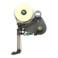
Avery Dennison ALS 256 Manuals
Manuals and User Guides for Avery Dennison ALS 256. We have
5
Avery Dennison ALS 256 manuals available for free PDF download: Service And Installation Manual, User Manual, Operating Instructions Manual, Installation Manual
Avery Dennison ALS 256 Service And Installation Manual (224 pages)
Brand:
Avery Dennison
| Category:
Label Maker
| Size: 8.7 MB
Table of Contents
Table of Contents
3
1 Please Observe the Following
6
General Information
6
Validity and Applicability of this Manual
6
Conventions and Information
7
Notes on Installation and Repair Work
8
Safety Instructions
10
Information and Qualifications
10
Machine Operating Safety
12
Safe Operation
13
2 Technical Data
15
Specifications
15
Characteristics
15
Labels
15
Label Sensor
15
Power Supply
15
Electronics
16
Interfaces
16
Internal Interfaces
16
Status Messages, Test Functions, Product
16
Profiles
16
Dimensions
17
Environmental Conditions
17
Integration
17
Certificates
17
Dimension Diagrams
18
Performance Data
20
Label Rate
20
Calculation Sheet for Performance Diagrams
21
Dispensing Speed over Duration V(T)
23
Dispensing Speed over Length V(X)
24
Dispensed Label Length over Duration X(T)
25
Performance Matrix (als 256)
26
3 Installation and Deinstallation
28
Unpacking, Assembling and Connecting the Machine
28
Transport
28
Unpacking
28
Setting up
29
Attaching the Dispensing Edge
33
Connecting to the Mains Power Supply
35
Connecting the External Operator Panel
38
Connecting the Sensors
39
Photoelectric Label Sensor
39
Alternative Label Sensor
44
Changing Light/Dark Switching at the Product Sensor or the Alternativ Label Sensor
47
Photoelectric Product Sensor
48
Photoelectric Roll Diameter Sensor
49
Rotary Encoder
53
Decommissioning, Dismantling, Disposal
56
Take the Machine out of Operation
56
Dismantling the Machine
56
Machine Disposal
56
4 Functions
57
Function Menu
57
Overview
57
Notes on the Description of Functions
59
LABEL SETUP Menu
59
MACHINE SETUP Menu
60
INTERFACE para Menu
65
Signal Interface
67
SERVICE/DIAGNOS. Menu
71
SERVICE DATA Menu
73
5 Operation
75
Automatic Dispensing Speed Adjustment
75
Principle of Operation
75
Mounting the Rotary Encoder
76
Entering the Rotary Encoder Resolution
77
Entering the Diameter of the Measuring
77
Wheel
77
Entering the Rotary Encoder Type
77
Example: Entering the Values for the Recommended Rotary Encoder
78
Calibrating the Belt Speed
78
Calculation Scheme for the Automatic Dispensing Speed Adjustment
79
Tandem Operation
81
Overview
81
Prerequisites
82
Setting up Tandem Operation
83
Applicator Operation
89
Function
89
System Requirements
89
Assembly and Operation
89
6 Enhanced Functions
90
Access Via a Web/Ftp Server
90
Web Server
90
FTP Server
94
Loading Firmware
95
Loading from Memory Card
95
Download Via Data Interface
95
Saving / Loading a Configuration
97
Applications
97
Saving Onto a Memory Card
97
Loading from Memory Card
98
Automatic Loading
98
Loading a Configuration Via the Data
99
Interface
99
Interface Commands
104
Reference Table
104
Immediate Commands
105
Forced Bootloader Start
111
Diagnose Dump
112
Storing Diagnosis Data
112
Reading out Via Serial Interface
113
Storing on CF Card
115
7 Electronics Description
116
Wiring Diagrams
116
Block Diagram
119
Electronics Components
120
Als 20X
120
Als 256
121
Circuit Boards
122
CPU Board
122
Motor Driver Board
127
Operator Panel Board
129
Applicator Interface
131
Power Supplies / Transformer
137
Power Supply als 20X
137
Transformer als 20X
139
Power Supply als 256
140
Signal Interface
141
General Notes
141
Circuit Diagrams for Signal Inputs
141
Signals for Applicator Connection
142
Applicator Type <--> Signals
143
Signal Wave Forms of Applicator Signals
144
Signals for PLC Connection
152
Impact of the Inhibit Signal
154
Data Interfaces
157
Rs 232
157
Connection for External Operator Panel
157
Ethernet
158
Integration of the Ethernet Interface
158
Applicator Interface (Option)
160
Important Notes
160
Circuit Diagrams for Signal Inputs
160
Circuit Diagrams for Signal Inputs
161
Power Outputs
161
Pin Assignment for Applicator Connection
162
Connection
164
Connection
166
Signal-Leds
167
Signal Wave Forms
167
8 Fault Description
168
Types of Status Messages
168
Error Messages
168
Warnings
168
Setting Back a Warning
168
General Software Errors
168
List of Warnings
168
List of Error Messages
169
9 Repair
178
Tests
178
Sensor Test
178
Initial State
180
Power Supply als
180
Power Supply Functions
180
Checking Output Voltages
181
Troubleshooting
183
Checking the Power Supply
185
Opening the Casing
186
Removing the Dust/Splash Guard
186
For Machines Held in Place by Side Plate or Base Plate
188
For Machines Held from the Rear Side
189
Unwind Unit
190
Expanding Mandrel
190
Brake
192
Dancer Arm
194
Feed Unit
205
Feed Roller Unit
205
Drive
207
Pressure Roller
210
Rewind Unit
213
Expanding Mandrel
213
Dancer Arm
215
Drive
221
Advertisement
Avery Dennison ALS 256 User Manual (68 pages)
Label Dispenser
Brand:
Avery Dennison
| Category:
Label Maker
| Size: 2.53 MB
Table of Contents
Table of Contents
3
1 Please Note
5
General Notes
5
Validity and Binding Effect of this Manual
5
Contents
5
Technical Status
5
Liability
5
Copyright
6
Manufacturer
6
Illustrations and Descriptions
7
Signs and Symbols
7
Dangers and Risk Notes
7
Figures
7
Button Symbols
7
Functions
7
Supplementary Information
7
Safety Instructions
8
Information and Qualifications
8
Qualification
8
Follow the Instructions
9
Keep the Product Information at Hand
9
Operational Safety of the Unit
10
Proper Usage
10
Protection against Injuries by Electrical Current
11
Protection against Injuries by Mechanical Action
12
Before Beginning Production
13
Due Diligence of the Operating Company and the Service Technician
13
Due Diligence of the User
13
Warning Notes on the Unit
14
2 Product Description
15
Overview
15
Components
15
Control Panel
17
Operating LED
17
Error LED
17
LCD Display
17
Buttons
17
Language
17
Connection Arrangement
18
Connections on the Back of the Device
18
Sensor Connections
19
Mode of Operation
20
Technical Specifications
21
Characteristics
21
Labels
21
Label Sensor
21
Power Supply
21
Electronics
22
Interfaces
22
Internal Interfaces
22
Status Messages, Test Functions, Product Profiles
22
Dimensions
23
Ambient Conditions
23
Integration
23
Certificates & Markings
23
Design Models
24
Right-Handed Version
24
Left-Handed Version
24
Options
25
External Control Panel
25
Fixed Dispensing Edge
25
Swivelling Dispensing Edge
25
Spring-Loaded Dispensing Edge
25
Pneumatic Dispensing Edge
26
V-Shape Dispensing Edge
26
Adjustable Dispensing Edge Holder
26
Outer Diameter Control Sensor
27
Dust/Splash Guard
27
Additional Material Guide Disk
27
Capacitive Label Sensor
28
Printer
28
Applicator
28
Applicator Interface
28
Narrow Label Spring Kit
28
Operating Modes
29
Dispensing Mode
29
Stopping /Continuing the Dispensing
29
Changing the Counter Reading
29
Resetting the Counter Reading
29
Starting the Unit in Configuration Mode
29
Counting Labels Backwards
29
Online Settings
30
Configuration Mode
31
Function of the Double-Arrow Button
31
Menus
31
Functions
32
Function Descriptions
33
Overview of Functions
33
Notes
35
Function Descriptions
35
Quick Setting
35
LABEL SETUP Menu
35
MACHINE SETUP Menu
36
3 Before Operation
38
Electrical Connections
38
Power Supply Connection
38
Checking the Power Supply Setting
39
Connecting the Power Cable
40
Connecting Sensors
40
Inserting Label Material
41
Inserting a Label Roll
41
Removing Spent Backing Paper
41
Removing Glue Residue
41
Inserting a New Label Roll
41
Threading the Label Roll
42
Threading Guide
42
Threading the Label Roll at the Dispensing Edge
43
Threading the Label Roll Onto the Drive Roller
44
Fastening the Label Roll to the Rewinder
44
Mechanical Settings
45
Adjusting the Unwinder's Core Diameter
45
Positioning the Pressure Roller
45
Positioning the Label Sensor
46
Setting the Dancer Arm Restoring Force
46
4 Operation
47
Start-Up and Shutdown
47
Turning on the Unit
47
Starting Label Dispensing
47
Dispensing with a Product Sensor
47
Dispensing Without a Product Sensor
47
Stopping/Continuing the Dispensing Process
47
Configuration and Monitoring
48
Function Menu Settings
48
Label Pitch
48
Label Stop Position
48
Dispensing Speed
49
Suppressing Start Signals
50
Label Position on the Product
50
Monitoring Functions
51
Material End / Roll Diameter
51
Missing Labels
52
Material Tear
52
Rewinder Full
53
Using Product Profiles
54
What Are Product Profiles
54
Loading a Product Profile
54
Storing a Product Profile
54
Selecting the Memory Location
54
Entering Profile Names
54
Deleting a Product Profile
55
5 After Operation
56
Maintenance and Cleaning
56
Replacing Fuses
56
Cleaning Agents
57
Regular Maintenance
58
Removing Paper Debris
58
Deflexion Rollers
58
Rubber Rollers
58
Renewal of the Dust Filter Liner (als 256)
58
6 Operational Failures
59
Status Messages
59
Types of Status Messages
59
Error Messages
59
Warnings
59
List of Warnings
59
List of Error Messages
60
EC Declarations
64
EC Declaration of Conformity
64
EC Declaration of Incorporation
65
Appendix Regarding the Declaration of Incorporation
66
Avery Dennison ALS 256 User Manual (62 pages)
Label Dispenser
Brand:
Avery Dennison
| Category:
Label Maker
| Size: 1.84 MB
Table of Contents
Table of Contents
3
1 Please Note
5
General Notes
5
Validity and Binding Effect of this Manual
5
Contents
5
Technical Status
5
Copyright
5
Manufacturer
5
Illustrations and Descriptions
6
Signs and Symbols
6
Dangers and Risk Notes
6
Figures
6
Button Symbols
6
Parameters
6
Supplementary Information
6
Safety Instructions
7
Information and Qualifications
7
Follow the Instructions
7
Keep the Product Information at Hand
7
Ensure the Required Qualifications Are Met
7
Operational Safety of the Unit
8
Proper Usage
8
Protection against Injuries by Electrical Current
8
Protection against Injuries by Mechanical Action
9
Protection against Injuries by Chemicals
9
Before Beginning Production
10
Due Diligence of the Operating Company and the Service Technician
10
Due Diligence of the User
10
Safety Notes on the Unit
11
2 Product Description
12
Overview
12
Components
12
Control Panel
14
Operating LED
14
Error LED
14
LCD Display
14
Buttons
14
Language
14
Connection Arrangement
15
Connections on the Back of the Device
15
Sensor Connections
16
Mode of Operation
17
Technical Specifications
18
Characteristics
18
Labels
18
Label Sensor
18
Power Supply
18
Electronics
19
Interfaces
19
Internal Interfaces
19
Status Messages, Test Functions, Product Profiles
19
Dimensions
20
Environmental Conditions
20
Integration
20
Certificates
20
Design Models
21
Right-Handed Version
21
Left-Handed Version
21
Options
22
External Control Panel
22
Fixed Dispensing Edge
22
Swivelling Dispensing Edge
22
Spring-Loaded Dispensing Edge
22
Pneumatic Dispensing Edge
23
V-Shape Dispensing Edge
23
Adjustable Dispensing Edge Holder
23
Outer Diameter Control Sensor
24
Dust/Splash Guard
24
Additional Material Guide Disk
24
Capacitive Label Sensor
25
Printer
25
Applicator
25
Applicator Interface
25
Narrow Label Spring Kit
25
Operating Modes
26
Dispensing Mode
26
Stopping /Continuing the Dispensing
26
Changing the Counter Reading
26
Starting the Unit in Configuration Mode
26
Counting Labels Backwards
26
Online Settings
27
Configuration Mode
28
Function of the Double-Arrow Button
28
Menus
28
Operating Modes
28
Functions
29
Function Descriptions
30
Overview of Functions
30
Notes
32
Function Descriptions
32
Quick Setting
32
LABEL SETUP Menu
32
MACHINE SETUP Menu
33
3 Before Operation
34
Electrical Connections
34
Power Supply Connection
34
Checking the Power Supply Setting
35
Connecting the Power Cable
35
Electrical Connections
35
Connecting Sensors
36
Inserting Label Material
37
Prerequisites
37
Inserting a Label Roll
38
Removing Spent Backing Paper
38
Removing Glue Residue
38
Inserting a New Label Roll
38
Threading the Label Roll
39
Threading Guide
39
Threading the Label Roll at the Dispensing Edge
40
Threading the Label Roll Onto the Drive Roller
41
Fastening the Label Roll to the Rewinder
41
Mechanical Settings
42
Adjusting the Unwinder's Core Diameter
42
Positioning the Pressure Roller
42
Positioning the Label Sensor
43
Setting the Dancer Arm Restoring Force
43
4 Operation
44
Start-Up and Shutdown
44
Turning on the Unit
44
Starting Label Dispensing
44
Dispensing with a Product Sensor
44
Dispensing Without a Product Sensor
44
Stopping/Continuing the Dispensing Process
44
Configuration and Monitoring
45
Function Menu Settings
45
Label Pitch
45
Label Stop Position
45
Dispensing Speed
46
Suppressing Start Signals
46
Label Position on the Product
47
Monitoring Functions
48
Material End / Roll Diameter
48
Missing Labels
49
Material Tear
49
Using Product Profiles
50
What Are Product Profiles
50
Loading a Product Profile
50
Storing a Product Profile
50
Selecting the Memory Location
50
Entering Profile Names
50
Deleting a Product Profile
51
5 After Operation
52
Maintenance and Cleaning
52
Replacing Fuses
52
Cleaning Agents
53
Regular Maintenance
54
Removing Paper Debris
54
Renewal of the Dust Filter Liner (als 256)
54
6 Operational Failures
55
Status Messages
55
Types of Status Messages
55
Error Messages
55
Warnings
55
List of Warnings
55
List of Error Messages
56
7 Appendix
60
Ec Declaration of Conformity
60
Avery Dennison Deutschland Gmbh Ohmstrasse
60
Advertisement
Avery Dennison ALS 256 Operating Instructions Manual (58 pages)
Label Dispenser
Brand:
Avery Dennison
| Category:
Label Maker
| Size: 1.42 MB
Table of Contents
Table of Contents
3
1 Please Note
5
General Notes
5
Validity and Binding Effect of this Manual
5
Contents
5
Technical Status
5
Copyright
5
Manufacturer
5
Illustrations and Descriptions
6
Signs and Symbols
6
Dangers and Risk Notes
6
Figures
6
Button Symbols
6
Parameters
6
Supplementary Information
6
Information and Qualifications
7
Follow the Instructions
7
Keep the Product Information at Hand
7
Ensure the Required Qualifications Are Met
7
Operational Safety of the Unit
8
Proper Usage
8
Protection against Injuries by Electrical Current
8
Protection against Injuries by Mechanical Action
9
Protection against Injuries by Chemicals
9
Before Beginning Production
10
Service Technician
10
Due Diligence of the User
10
Safety Notes on the Unit
11
2 Product Description
12
Overview
12
Components
12
Control Panel
14
Operating LED
14
Error LED
14
LCD Display
14
Buttons
14
Connection Arrangement
15
Connections on the Back of the Device
15
Sensor Connections
16
Mode of Operation
17
Technical Specifications
18
Characteristics
18
Labels
18
Label Sensor
18
Power Supply
18
Electronics
19
Interfaces
19
Internal Interfaces
19
Status Messages, Test Functions, Product Profiles
19
Dimensions
20
Environmental Conditions
20
Integration
20
Certificates
20
Design Models
21
Right-Handed Version
21
Left-Handed Version
21
Options
22
External Control Panel
22
Fixed Dispensing Edge
22
Swivelling Dispensing Edge
22
Spring-Loaded Dispensing Edge
22
Pneumatic Dispensing Edge
23
V-Shape Dispensing Edge
23
Adjustable Dispensing Edge Holder
23
Outer Diameter Control Sensor
24
Printer
24
Applicator
24
Applicator Interface
24
Dust/Splash Guard
24
Operating Modes
25
Dispensing Mode
25
Stopping /Continuing the Dispensing Mode
25
Changing the Counter Reading
25
Starting the Unit in Configuration Mode
25
Counting Labels Backwards
25
Online Settings
26
Configuration Mode
27
Function of the Double-Arrow Button
27
Menus
27
Functions
28
Function Overview
29
Notes on Function Descriptions
31
LABEL SETUP Menu
31
MACHINE SETUP Menu
31
SERVICE DATA Menu
32
MODULE FW VERS. Submenu
32
OPERATIONAL DATA Submenu
32
POWER SUPPLY DATA Submenu
32
CPU BOARD DATA Submenu
32
DISPLAY DATA Submenu
32
CF CARD SLOT Submenu
32
PERIPHERAL DATA Submenu
32
MEMORY DATA Submenu
32
3 Before Operation
33
Electrical Connections
33
Power Supply Connection
33
Checking the Power Supply Setting
34
Connecting the Power Cable
34
Connecting Sensors
35
Inserting Label Material
36
Prerequisites
36
Inserting a Label Roll
37
Removing Spent Backing Paper
37
Removing Glue Residue
37
Inserting a New Label Roll
37
Threading the Label Roll
38
Threading Guide
38
Threading the Label Roll at the Dispensing Edge
39
Threading the Label Roll Onto the Drive Roller
40
Fastening the Label Roll to the Rewinder
40
Adjusting the Unwinder's Core Diameter
41
Positioning the Pressure Roller
41
Positioning the Label Sensor
42
Start-Up and Shutdown
43
Turning on the Unit
43
Starting Label Dispensing
43
7 Appendix
43
Dispensing with a Product Sensor
43
Dispensing Without a Product Sensor
43
Stopping the Dispensing Process
44
Configuration and Monitoring
45
Function Menu Settings
45
Label Pitch
45
Label Stop Position
45
Dispensing Speed
46
Label Position on the Product
47
Monitoring Functions
48
Missing Labels
48
Material End
48
Material Tear
48
What Are Product Profiles
49
Loading a Product Profile
49
Storing a Product Profile
49
Selecting the Memory Location
49
Entering Profile Names
49
Deleting a Product Profile
50
5 After Operation
51
Maintenance and Cleaning
51
Replacing Fuses
51
Cleaning Agents
52
Regular Maintenance
53
Removing Paper Debris
53
Renewal of the Dust Filter Liner (als 256)
53
6 Operational Failures
54
Error Messages
54
Reporting Errors
54
List of Error Messages
54
Avery Dennison Deutschland Gmbh Ohmstrasse
57
Avery Dennison ALS 256 Installation Manual (43 pages)
Labeller
Brand:
Avery Dennison
| Category:
Printer
| Size: 2.21 MB
Table of Contents
Table of Contents
3
Please Observe the Following
4
General Information
4
Validity and Applicability of this Manual
4
Contents
4
Technical State
4
Liability
4
Copyright Notice
4
Manufacturer
4
Conventions and Information
5
Explanation of Symbols
5
Warnings Concerning Dangers and Risks
5
Illustrations
5
Symbols for Keys
5
Functions
5
Supplemental Information
5
Notes on Installation and Repair Work
6
General Information
6
Environmental Protection
6
Rules for Electromagnetic Compatibility
7
Safety Instructions
8
Information and Qualifications
8
Qualification
8
Pay Attention to the Information
9
Information Must be Made Available
9
Machine Operating Safety
10
Installation, Maintenance
10
Protection Measures in Applicator Mode
10
After All Servicing or Repair Work
10
Safe Operation
11
Protect against Injuries that Can Result from Electrical Current
11
Protection against Injuries that Can Result from Mechanical Actions
12
Installation and Deinstallation
13
Unpacking, Assembling and Connecting the Machine
13
Transport
13
Unpacking
13
Setting up
14
For Machines Held from the Rear Side
15
Holding Machine in Place by Side Plate or Base Plate
17
Attaching the Dispensing Edge
18
L-Shaped Dispensing Edge
18
V-Shaped Dispensing Edge
19
Adjustable Dispensing Edge Holder
19
Connecting to the Mains Power Supply
20
Checking the Supply Voltage Setting
21
Plugging in the Power Lead
22
Connecting the External Operator Panel
23
Mounting the External Operator Panel
23
Connecting the Sensors
24
Photoelectric Label Sensor
24
Connecting the Photoelectric Sensor
24
Pin Assignment
24
Connection Diagram
25
Adjusting the Avery Sensor
26
Switching the Avery Sensor - PNP/NPN
27
Adjusting the Wenglor Photoelectric Sensor Automatically
28
Adjusting the Wenglor Photoelectric Sensor Manually
28
Alternative Label Sensor
29
Connecting the Sensor
29
Pin Assignment
29
Connection Diagram
30
Example: Capacitive Label Sensor
30
Changing Light/Dark Switching at the Product Sensor or the Alternativ Label Sensor
32
Gen. 1
32
Gen. 2
33
Photoelectric Product Sensor
34
Connecting the Photoelectric Sensor
34
Pin Assignment
34
Connection Diagram
34
Photoelectric Roll Diameter Sensor
35
Installing
35
Connecting the OD Sensor
36
Pin Assignment
36
Connection Diagram
36
Enabling
37
Setting the Roll Diameter
37
Function Test
38
Rotary Encoder
39
Requirements for Rotary Encoder
39
Connecting the Rotary Encoder
40
Connection Diagram
40
Decommissioning, Dismantling, Disposal
41
Take the Machine out of Operation
41
Dismantling the Machine
41
Machine Disposal
41
Advertisement
Related Products
Avery Dennison ALS 230
Avery Dennison ALS 206
Avery Dennison ALS 204
Avery Dennison ALS 221
Avery Dennison ALS 341
Avery Dennison ALS 330
Avery Dennison ALS 350
Avery Dennison ALS 450
Avery Dennison ALS 380
Avery Dennison ALS 321
Avery Dennison Categories
Printer
Label Maker
Printer Accessories
Barcode Reader
Battery Charger
More Avery Dennison Manuals
Login
Sign In
OR
Sign in with Facebook
Sign in with Google
Upload manual
Upload from disk
Upload from URL