Avery Dennison ALS 204 User Manual
Label dispenser
Hide thumbs
Also See for ALS 204:
- Service and installation manual (224 pages) ,
- User manual (68 pages) ,
- Operating instructions manual (58 pages)
Table of Contents
Advertisement
Quick Links
Advertisement
Table of Contents

Related Manuals for Avery Dennison ALS 204


Summary of Contents for Avery Dennison ALS 204
- Page 1 ANUAL Label Dispenser 204/206 Edition 7 04/2010...
-
Page 3: Table Of Contents
ONTENTS Please note 2.1.5 Technical specifications ....18 Characteristics ......18 1.1 General notes Labels . - Page 4 ONTENTS 2.4 Function descriptions 4.2 Configuration and monitoring 2.4.1 Overview of functions ....30 4.2.1 Function menu settings ....45 Label pitch .
-
Page 5: Please Note
Validity and binding effect of this manual 1.1.1 Contents Copyright The present manual refers exclusively to the ALS 204, Avery Dennison holds all rights to this manual and its ALS 206 and ALS 256 label dispensers. It is written for appendices. Reproduction, reprinting or any other... -
Page 6: Illustrations And Descriptions
LEASE NOTE 1.1 G ENERAL NOTES Illustrations and descriptions 1.1.2 Signs and symbols Figures Various information types are indicated in different Texts are accompanied by figures where necessary. ways within the document in order to simplify Figures are indicated using figure numbers in [square readability and comprehension. -
Page 7: Safety Instructions
LEASE NOTE 1.2 S AFETY INSTRUCTIONS SAFETY INSTRUCTIONS Information and qualifications Ensure the required qualifications are met 1.2.1 Ensure that only trained and authorized personnel Follow the instructions operate, configure and service the unit. WARNING! Only allow qualified and well-trained expert personnel or service technicians to perform Safe and efficient operation of the label configurations. -
Page 8: Operational Safety Of The Unit
LEASE NOTE 1.2 S AFETY INSTRUCTIONS Operational safety of the unit 1.2.2 Proper usage Only link the unit to devices that fulfil the SELV (safety extra-low voltage) circuit The label dispenser is a fully automatic unit for requirements specified in EN 60950. attaching self-adhesive labels to products or Make sure that the power switch at the packaging. -
Page 9: Protection Against Injuries By Mechanical Action
LEASE NOTE 1.2 S AFETY INSTRUCTIONS Protection against injuries by mechanical action WARNING! Risk of injury due to moving and rapidly rotating parts! – Long hair, loose jewellery, long sleeves, and so on are not permissible when using the unit. Sufficient protective clothing must be worn. -
Page 10: Before Beginning Production
LEASE NOTE 1.2 S AFETY INSTRUCTIONS Before beginning production 1.2.3 Due diligence of the operating company Due diligence of the user and the service technician Check that the safety installations are working properly. Ensure that the following prerequisites are fulfilled in Inspect the machinery for any visible damage. -
Page 11: Safety Notes On The Unit
LEASE NOTE 1.2 S AFETY INSTRUCTIONS Safety notes on the unit 1.2.4 CAUTION! Warning notes on the unit represent important information for the personnel using it. Do not remove warning notes. Replace any missing or illegible warnings. The ‘Pinch Point’ warning ] note warns you of the danger posed by the machine’s rotating parts;... -
Page 12: Product Description
RODUCT DESCRIPTION 2.1 O VERVIEW R O DU C T D E SC R IPT IO N OVERVIEW Components 2.1.1 ALS 256 [3] ALS 204 Label Dispenser (right-handed version) - Page 13 RODUCT DESCRIPTION 2.1 O VERVIEW A Control panel J Dispensing edge – For sending commands to the device and for – Standard: (non-adjustable) L-shaped dispensing displaying operating states and error messages. edge – An optional external control panel can also be –...
-
Page 14: Control Panel
RODUCT DESCRIPTION 2.1 O VERVIEW Control panel 2.1.2 Operating LED STATUS Lights up green when the device is switched on. Online Labels Error LED – – Lights up red when an error occurs. LCD display – Displays functions, configured values, operating states and error messages. -
Page 15: Connection Arrangement
RODUCT DESCRIPTION 2.1 O VERVIEW Connection arrangement 2.1.3 Connections on the back of the device [5] Connections on the back of the device (ALS 20x): E Plug-in card slot (CompactFlash cards) A Power supply connection F USB device interface B Network connection (Ethernet 10/100) G PLC signal interface C Serial interface (RS232) H Optional: Applicator interface... -
Page 16: Sensor Connections
RODUCT DESCRIPTION 2.1 O VERVIEW Sensor connections [6] Sensor connections on the ALS 20x (RH) PLC-IN PLC-OUT PLC-OUT PLC-IN START START ROTARY ROTARY ENCODER ENCODER LABEL LABEL CAP for 256 CAP for 256 [7] Arrangement of the sensor connections (schematic) on the LH (left figure) and RH (right figure) devices: A Product sensor B Signal outputs (optional) -
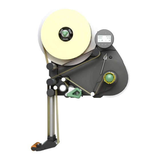
Page 17: Mode Of Operation
RODUCT DESCRIPTION 2.1 O VERVIEW Mode of operation 2.1.4 In labelling mode, the strip is first pulled from the label roll around the dancer arm [8A], which consistently maintains even tension in the label strip. The feed roller [8D] behind the dispensing edge [8C] draws the strip across the dispensing plate. -
Page 18: Technical Specifications
RODUCT DESCRIPTION 2.1 O VERVIEW Technical specifications 2.1.5 Characteristics Label sensor Dispensing speed Distance to peel edge ALS 204 max. 40 m/min L-shape dispensing ALS 206 max. 30 m/min edge: 19 mm ALS 256 max. 50 m/min V-shape dispensing edge:... -
Page 19: Electronics
RODUCT DESCRIPTION 2.1 O VERVIEW Electronics Data interfaces: Processor: 32 Bit CPU MIPS Core Serial: RS232C (Sub-D9), max. 115 200 Baud RAM: 16 MB Ethernet: 10/100 BaseT (RJ45) ROM: 4 MB USB: Device V1.1 (USB B), Control panel: graphical display with ‘Full speed’... -
Page 20: Dimensions
– CE, TÜV/GS, FCC, CCC, GOST, NRTL, US/CA Width x height x depth: – The regulation DIN EN 55022 demands for class A ALS 204 492 x 488 x 353 mm devices the following text to be printed in the... -
Page 21: Design Models
RODUCT DESCRIPTION 2.1 O VERVIEW Design models 2.1.6 The ALS 20X and ALS 256 label dispensers are availa- ble in two designs for differing conveyor belt directions. Right-handed version – The products are transported from left to right [9]. – The dispensing edge is located on the right side. –... -
Page 22: Options
RODUCT DESCRIPTION 2.2 O PTIONS OPTIONS External control panel – An external control panel can be connected in addition to the integrated control panel. – An external control panel is useful if the standard control panel is difficult to access due to the position in which the unit is installed. -
Page 23: Pneumatic Dispensing Edge
RODUCT DESCRIPTION 2.2 O PTIONS Pneumatic dispensing edge – The dispensing edge is pivoted in the dispensing head. Compressed air presses the dispensing edge onto the surface of the product. – Allows compensation for height differences between the products or on the product surface. [15] Pneumatic dispensing edge V-shape dispensing edge Not for ALS 256! -
Page 24: Outer Diameter Control Sensor
RODUCT DESCRIPTION 2.2 O PTIONS Outer Diameter control sensor The outer diameter control sensor (OD sensor) triggers a warning, if the label roll outer diameter falls below a certain, adjustable value. [18] OD sensor (pictured red resp. dark gray) Dust/Splash guard Available only for ALS 20X. -
Page 25: Capacitive Label Sensor
[21] Capacitive label sensor with bracket and cable. Printer – If necessary, you can mount a hot stamp printer (not available from Avery Dennison) onto the holder brackets of the dispensing edge. – Example of use: Printing consecutive numbers onto labels. -
Page 26: Operating Modes
RODUCT DESCRIPTION 2.3 O PERATING MODES OPERATING MODES Dispensing mode 2.3.1 This is the operating mode of the unit when switched on. You can carry out the functions listed in the sections STATUS below. Online If text such as ‘Prof 5 xxxxxxxx’ is displayed Labels instead of ‘ONLINE’: –... -
Page 27: Online Settings
– You can increase (‘+’ button) or lower (‘–’ button) both settings in the dispensing mode [23D]. Dispensing speed: – Setting range: ALS 204: [5.0…40.0] m/min ALS 206: [5.0…30.0] m/min [23] Control panel in the online settings mode ALS 256: [5.0…50.0] m/min A Dispensing speed display (here: 12.2 m/min constant) -
Page 28: Configuration Mode
RODUCT DESCRIPTION 2.3 O PERATING MODES Configuration mode 2.3.2 The machine is in dispensing mode. Switching to configuration mode: STATUS Press the button twice. OFFLINE – Display: OFFLINE – – Press the button. – Display: LABEL SETUP LABEL SETUP – LABEL SETUP is the name of the first menu that is currently active. -
Page 29: Functions
RODUCT DESCRIPTION 2.3 O PERATING MODES Functions MACHINE SETUP Every submenu contains functions for setting the unit controls. Figure [25] shows the button functions for changing MACHINE SETUP > Language settings using the function as MACHINE SETUP an example. Store Prod.Prof. MACHINE SETUP Language Language... -
Page 30: Function Descriptions
RODUCT DESCRIPTION 2.4 F UNCTION DESCRIPTIONS FUNCTION DESCRIPTIONS Overview of functions 2.4.1 (continued) (continued) LABEL SETUP MACHINE SETUP INTERFACE PARA > EASYPLUGINTERPR Load prod.profil Dispenser type Light sens. type Port address Gap detect mode Store prod.prof. Labelsen. InType Interface Ethernet speed Dispense speed Del. - Page 31 RODUCT DESCRIPTION 2.4 F UNCTION DESCRIPTIONS (continued) (continued) SIGNAL INTERFACE SERVICE/DIAGNOS. SERVICE DATA > AI BOARD SIGNAL Interface mode Service > MODULE FW VERS. Manufacturer > PLC SIGNALS Applicator type Serv. data reset System version Work place End dispense mod Apply mode Sensor Test System revision...
-
Page 32: Notes
– The speed at which the label is dispensed highlighted in grey in the overview. – Setting range: ALS 204: [5.0…40.0] m/min; default: 10.0 Settings of functions that are not described in ALS 206: [5.0…30.0] m/min; default: 10.0 the following may only be changed by qualified ALS 256: [5.0…50.0] m/min;... -
Page 33: Machine Setup Menu
RODUCT DESCRIPTION 2.4 F UNCTION DESCRIPTIONS MACHINE SETUP menu „3 labels/start“: Each start signal causes printing of 2.4.4 3 labels. Store prod. prof. function: Label 2 offset function: – Storing a product profile, see chap. “Storing a – Defines the distance of the 2nd label for the product profile”... -
Page 34: Before Operation
EFORE OPERATION 3.1 E LECTRICAL CONNECTIONS E FO R E O PE R AT IO N ELECTRICAL CONNECTIONS Power supply connection 3.1.1 WARNING! This machine operates using mains voltage! Touching live electrical parts may expose you to hazardous electrical currents and may lead to burns. -
Page 35: Checking The Power Supply Setting
EFORE OPERATION 3.1 E LECTRICAL CONNECTIONS Checking the power supply setting ALS 256: A power supply setting is not re- quired. The ALS 20X Label Dispenser is suitable for operation with a power supply of 230 V (AC) or 110 V (AC). If you are unsure of what mains voltage your local electricity supplier provides, refer to a qualified service technician. -
Page 36: Connecting Sensors
EFORE OPERATION 3.1 E LECTRICAL CONNECTIONS Connecting sensors 3.1.2 Check whether the required sensors are connected before turning on the unit [33]. The minimum required sensors: – Label sensor (installation location: dispensing edge) – Product sensor (installation location: conveyor belt) Additional optional sensors: –... -
Page 37: Inserting Label Material
EFORE OPERATION 3.2 I NSERTING LABEL MATERIAL INSERTING LABEL MATERIAL Prerequisites 3.2.1 – The label dispenser is turned off at the main switch [34A] (switch set to ‘O’). Check that the safety installations are working properly. Inspect the machinery for any visible damage. Report any defects immediately. -
Page 38: Inserting A Label Roll
EFORE OPERATION 3.2 I NSERTING LABEL MATERIAL Inserting a label roll 3.2.2 WARNING! Risk of injury due to moving and rapidly rotating parts! Before inserting the label roll, ensure that the device is turned off at the main switch. Do not under any circumstances turn the device on before the label strip is threaded in completely. -
Page 39: Threading The Label Roll
EFORE OPERATION 3.2 I NSERTING LABEL MATERIAL Threading the label roll 3.2.3 Threading guide [37] Threading guide for ALS 20x/256 with L-shape dispensing edge A Right-handed version B Left-handed version [38] Threading guide for ALS 20x/256 with V-shape dispensing edge A Right-handed version B Left-handed version *) Solid line: Path for label rolls with labels facing outwards. -
Page 40: Threading The Label Roll At The Dispensing Edge
EFORE OPERATION 3.2 I NSERTING LABEL MATERIAL Threading the label roll at the dispensing edge Fixed [39] (standard) and pivotable L-Shape dispen- sing edges: Unroll around 1 m of label strip and remove the labels from it. Pass the backing paper around the first deflection roller [39A] and through the slot in the sensor [39B]. -
Page 41: Threading The Label Roll Onto The Drive Roller
EFORE OPERATION 3.2 I NSERTING LABEL MATERIAL Threading the label roll onto the drive roller Open the pressure roller. To do so, rotate the lever [42D] in a clockwise direction. Feed the backing paper around the deflection roller [42B], drive roller [42C] and the dancer arm [42A]. Close the pressure roller. -
Page 42: Mechanical Settings
EFORE OPERATION 3.3 M ECHANICAL SETTINGS MECHANICAL SETTINGS Adjusting the unwinder’s core 3.3.1 diameter Tool: – 3 mm hexagon (Allen) screwdriver The unwinder can be adjusted with core adapters [45B] to fit the inner diameter of the label roll. The adapters must be fitted and dismantled in different ways depending on this diameter: –... -
Page 43: Positioning The Label Sensor
EFORE OPERATION 3.3 M ECHANICAL SETTINGS Positioning the label sensor 3.3.3 Release the thumb screw. Position the sensor along the axle in such a way as to allow it to register the spaces between the labels. The LED [48A] lights up when the sensor is positioned over a label. -
Page 44: Operation
PERATION 4.1 S TART UP AND SHUTDOWN P E RA TIO N START-UP AND SHUTDOWN Turning on the unit Dispensing without a product sensor 4.1.1 It is also possible to trigger the dispensing process without a product sensor: – The machine is in dispensing mode: Press the button. -
Page 45: Configuration And Monitoring
PERATION 4.2 C ONFIGURATION AND MONITORING CONFIGURATION AND MONITORING Function menu settings 4.2.1 Label pitch Switch to configuration mode Calibrating the label pitch automatically: Hold down the button for a while (longer than two seconds). Or: Enter the label pitch manually: Measure the label pitch [51C]. -
Page 46: Dispensing Speed
PERATION 4.2 C ONFIGURATION AND MONITORING Dispensing speed You can set the dispensing speed to a fixed value or you can configure it to automatically adjust to the speed of the conveyor belt (speed adaption). The second option requires you to connect a rotary encoder that measures and relays the conveyor speed to the dispenser. -
Page 47: Label Position On The Product
PERATION 4.2 C ONFIGURATION AND MONITORING Label position on the product Prerequisites: – The label length must be specified. – The label stop position must be set. Configuration in dispensing mode: Use the two right buttons to set the start offset (see “Online settings”... -
Page 48: Monitoring Functions
PERATION 4.2 C ONFIGURATION AND MONITORING Monitoring functions 4.2.2 While in dispensing mode, an electronic controller monitors the following functions: Material end / Roll diameter (OD = outer diameter) To enable a quick renewal of the material roll, the machine can alarm the operator before the end of the material roll is reached. -
Page 49: Missing Labels
PERATION 4.2 C ONFIGURATION AND MONITORING If an error message occurs: – The machine stops. Press the button to delete the message. Remove the rewound backing paper. Insert a new material roll (see “Inserting a label roll” on page 37). Missing labels A label missing from the label roll does not normally affect the dispensing operation, because the label feed... -
Page 50: Using Product Profiles
PERATION 4.3 U SING PRODUCT PROFILES USING PRODUCT PROFILES What are product profiles? Storing a product profile 4.3.1 4.3.3 Product profiles are memory locations that can store all Selecting the memory location the settings for the machine controls. For recurring MACHINE SETUP >... -
Page 51: Deleting A Product Profile
PERATION 4.3 U SING PRODUCT PROFILES – The profile is saved. – Display: Store prod.prof. Storing… – The product profile has now been saved. Deleting a product profile 4.3.4 MACHINE SETUP > Del. prod.profil Call the function. – The memory location that was active last is displayed. -
Page 52: After Operation
FTER OPERATION 5.1 M AINTENANCE AND CLEANING FT ER O P ER A TIO N MAINTENANCE AND CLEANING Replacing fuses Tool: Screwdriver 5.1.1 This section counts only for ALS 20X. The fu- ses at the ALS 256 cannot be replaced. Turn off the unit. -
Page 53: Cleaning Agents
FTER OPERATION 5.1 M AINTENANCE AND CLEANING Cleaning agents 5.1.2 Cleaning agents for rubber rollers: – Roller cleaner, order number 98925. If other cleaning agents are used, there is a chance the rubber may corrode. Cleaning agents for metal deflection rollers: –... -
Page 54: Regular Maintenance
FTER OPERATION 5.1 M AINTENANCE AND CLEANING Regular maintenance 5.1.3 The label dispenser is designed to be maintenance-free. However, you should service the unit regularly in order to ensure reliable long-term operating results. Removing paper debris Depending on operating conditions, you should perform the following at least once a week: Wipe the paper residue from the rollers and edges. -
Page 55: Operational Failures
PERATIONAL FAILURES 6.1 S TATUS MESSAGES PE R AT IO N AL FA IL UR E S STATUS MESSAGES Types of status messages List of warnings 6.1.1 6.1.2 Error messages Displayed text Meaning When an error occurs, the machine stops immediately Produktstartwarn New start signal during the and displays an error message on the control panel. -
Page 56: List Of Error Messages
PERATIONAL FAILURES 6.1 S TATUS MESSAGES List of error messages 6.1.3 Status Status text Cause Action to take 5000 Bus device – Device at I C Bus cannot be Delete the message by pressing the contacted. -key. – In most cases, this message appears Switch the machine off, wait 30 as the first in a series of two or three seconds and switch it back on. - Page 57 PERATIONAL FAILURES 6.1 S TATUS MESSAGES Status Status text Cause Action to take 5140 Rewinder control Rewinder control Press the key. – This reinitialises the dancer arm During problem-free operation, control; the dancer arm moves back the rewind unit dancer arm only into the control position.
- Page 58 PERATIONAL FAILURES 6.1 S TATUS MESSAGES Status Status text Cause Action to take 5147 Tandemsynch. Init This message can only appear Check, if the slave machine had during tandem operation. been switched on before the master machine - if not, repeat the switching on in the correct order (first slave, –...
- Page 59 PERATIONAL FAILURES 6.1 S TATUS MESSAGES Status Status text Cause Action to take 9022 No network link This status message can only appear Check whether the network when Ethernet address assignment is connector is plugged in correctly, (INTERFACE PARA > set to DHCP correct if necessary.
-
Page 60: Appendix
EU directives. Name of the devices: ALS 204, ALS 206, ALS 256 Device type: Label dispenser... - Page 62 Avery Dennison Deutschland GmbH Ohmstraße 3 85386 Eching Germany Telephone: +49-8165-925-0 http://www.machines.averydennison.com...
Need help?
Do you have a question about the ALS 204 and is the answer not in the manual?
Questions and answers