
Subscribe to Our Youtube Channel
Related Manuals for Automatic Technology Elite


Summary of Contents for Automatic Technology Elite
- Page 1 Elite® Swing Gate Opener Technical Document Installation Manual 3.01 14 Dec 2011 English Part # 13295 (Manual) INSTALLATION INSTRUCTIONS | OWNERS COPY...
- Page 2 Automatic Technology Australia Pty Ltd to the extent that such may be lawfully excluded hereby expressly disclaims all conditions or warranties, statutory or otherwise which may be implied by laws as conditions or warranties of purchase of an Automatic Technology Australia Pty Ltd Elite®...
-
Page 3: Table Of Contents
Menu 8.4 Memory Usage Accessories Installation Menu 8.5 Service Counter Battery Backup Installation Menu 8.6 Counters Troubleshooting Guide Memory Tools Specifi cations Menu 9.1 Clr Control Spare Parts List Menu 9.2 Clr Tx’ers Warranty Owner Installation Instructions Elite® - Swing Gate Opener... -
Page 4: Important Safety Instructions
FOR ADDITIONAL SAFETY protection we strongly recommend the fi tting of a Photo Electric (PE) Beam. In most countries, PE Beams are mandatory on all gates fi tted with automatic openers. For a small additional outlay, Automatic Technology recommends that Photo Electric Beams be installed with the automatic opener ensuring additional safety and peace of mind. - Page 5 The Elite® swing gate opener should not be immersed in water or sprayed directly by a hose or other water carrying device. The gate(s) must be well balanced and in good working order. Faulty gates must be repaired by a qualifi...
-
Page 6: Features
Even if two of the three signals are jammed, the system will still work. Security Code Store The Elite® Swing Gate Opener uses revolutionary technology to securely store up to fi ve hundred and eleven (511) transmitters in its memory with the ability to assign an 11 character name to each. - Page 7 (3) PE Beam response modes and two (2) pedestrian response modes. SmartSolar™ and Battery Backup Compatibility (optional) The Elite® swing gate opener can be fi tted with a SmartSolar™ or Battery Backup kit for operation in the event of a power outage, or where mains power access is not available.
-
Page 8: Kit Contents
ITEM DESCRIPTION Drive Unit Drive Arm Extension Slave Arm Gate Mounting Bracket Plastic Washer Shoulder Screw Hex Head Screw Spring Washer Flat Washer Control Box Control Box Mounting Bracket PTX-5 Keyring Transmitter Elite® - Swing Gate Opener Owner Installation Instructions... -
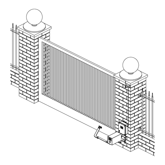
Page 9: Drive Unit Installation
Ensure sideroom clearance is adequate. Refer Mounting The Drive Unit to Table on page 10. If there is not enough The Elite® swing gate opener is designed to operate sideroom available, the Minimum Sideroom Kit most residential swing gates. The gates must be in (Page 12) is required. - Page 10 (Fig. 04, 05 & 06) Engaged To re-engage, pull pin and rotate motor assembly anti- fi g position clockwise until manual release pin clicks into place. fi g Disengaged position Elite® - Swing Gate Opener Owner Installation Instructions...
-
Page 11: Installing Drive Unit Arms
Remove the Gate Mounting Bracket from the Slave Arm and secure the Gate Mounting Bracket to the gate at second mark. Reassemble Slave Arm to Gate Mounting Bracket using shoulder screw and plastic washers. Secure fi rmly. Owner Installation Instructions Elite® - Swing Gate Opener... -
Page 12: Installing Minimum Sideroom Kit
Connect drive unit(s) to control board using 5- core or 3-core cable.Two diodes IN4001 per drive unit must be used with 3-core cable instalation. For detailed electrical connection see (Fig. 14 -21). Elite® - Swing Gate Opener Owner Installation Instructions... - Page 13 Open the gate to the required opening position and turn top cam in an clockwise direction until a click can be heard from lower micro-switch. Top cam fi g Lower cam Owner Installation Instructions Elite® - Swing Gate Opener...
-
Page 14: Five Wire Connection Single Leaf
MOTOR 1 CLOSE LIMIT SWITCH INPUT MOTOR 1 OPEN LIMIT SWITCH INPUT MOTOR 1 CONNECTOR 1 MOTOR 1 CONNECTOR 2 24 VOLTS DC OUTPUT PLUS (+) 24 VOLTS DC OUTPUT MINUS (-) Elite® - Swing Gate Opener Owner Installation Instructions... -
Page 15: Five Wire Connection Dual Leaf
MOTOR 1 CLOSE LIMIT SWITCH INPUT MOTOR 1 OPEN LIMIT SWITCH INPUT MOTOR 1 CONNECTOR 1 MOTOR 1 CONNECTOR 2 24 VOLTS DC OUTPUT PLUS (+) 24 VOLTS DC OUTPUT MINUS (-) Owner Installation Instructions Elite® - Swing Gate Opener... -
Page 16: Three Wire Connection Single Leaf
MOTOR 1 CLOSE LIMIT SWITCH INPUT MOTOR 1 OPEN LIMIT SWITCH INPUT MOTOR 1 CONNECTOR 1 MOTOR 1 CONNECTOR 2 24 VOLTS DC OUTPUT PLUS (+) 24 VOLTS DC OUTPUT MINUS (-) Elite® - Swing Gate Opener Owner Installation Instructions... -
Page 17: Three Wire Connection Dual Leaf
MOTOR 1 CLOSE LIMIT SWITCH INPUT MOTOR 1 OPEN LIMIT SWITCH INPUT MOTOR 1 CONNECTOR 1 MOTOR 1 CONNECTOR 2 24 VOLTS DC OUTPUT PLUS (+) 24 VOLTS DC OUTPUT MINUS (-) Owner Installation Instructions Elite® - Swing Gate Opener... -
Page 18: Control Board Layout
MOTOR 2 open limit switch input terminal COM terminal for Terminals 16,17,19 & 20. MOTOR 1 close limit switch input terminal MOTOR 1 open limit switch input terminal MOTOR 1 terminal 1 MOTOR 1 terminal 2 Elite® - Swing Gate Opener Owner Installation Instructions... - Page 19 Control Board Layout fi g Owner Installation Instructions Elite® - Swing Gate Opener...
-
Page 20: Menu Structure
Menu Structure Elite® - Swing Gate Opener Owner Installation Instructions... -
Page 21: Setting Travel Limits
(Fig. 26) and that the gate(s) are in a fully open position and engaged. Press SET to confi rm (Fig. 27). Fully Open Gate Engage Mtrs, SET fi g PREV NEXT EXIT Owner Installation Instructions Elite® - Swing Gate Opener... - Page 22 When the setup is complete, the MAIN SCREEN will be displayed “Gate is closed”. The gate can now be used. Elite® - Swing Gate Opener Owner Installation Instructions...
-
Page 23: Coding Transmitters
PED (Pedestrian access) OSC (Open/Stop/Close) OFF (No action) Press SET to save the settings (Fig. 37) or EXIT to abort without saving. Press EXIT to return to the MAIN SCREEN and test the transmitter. Owner Installation Instructions Elite® - Swing Gate Opener... -
Page 24: Standard Operating Modes
While in pedestrian access mode, the pedestrian access position temporarily becomes the open limit for the gate leaf. The PED input then acts with an OSC type function. The pedestrian access mode is exited when the gate is closed or when another input is activated. Elite® - Swing Gate Opener Owner Installation Instructions... -
Page 25: Control Board Adjustments
Unit Menu M1 MARGIN Sets obstruction detection margin for M1 AMPS M2 MARGIN Sets obstruction detection margin for M2 AMPS SETTLE TIME disable the obstruction detection in the start of the cycle Owner Installation Instructions Elite® - Swing Gate Opener... -
Page 26: Menu 3 Auto-Close Times
05 starts a timer once the gate has reached its desired open position. The timer then counts down and when it expires, the DCB-05 starts to close the gate. Details of the four Auto-Close modes are outlined below. Automatic Technology strongly recommend using a PE Beam for added safety. Standard Auto-Close... -
Page 27: Menu 4 Lock Times
The value calculated is selected so that the delay between M2 and M1 reaching the close position is equal to the OPEN SYNC DELAY TIME. The MAX OVERRUN TIME is set to 0 for TIMED TRAVEL installations. Owner Installation Instructions Elite® - Swing Gate Opener... -
Page 28: Menu 7 Operating Modes
In this mode, the PE input has no effect when DCB-05 supports the Remote Code Set feature. This opening but will stop the gate when closing. parameter can be used to disable the feature for security or transmitter management reasons. Elite® - Swing Gate Opener Owner Installation Instructions... - Page 29 Selects function of OUTPUT1 and OUTPUT2 LOCK LIGHT LOCK OUTPUT2= OUTPUT2= OUTPUT2= LIGHT LOCK LIGHT OPN INPUT = 2ND PE 7.11 Open input acts as 2nd PE input FAULT AUTO RESET 7.12 Owner Installation Instructions Elite® - Swing Gate Opener...
-
Page 30: Diagnostic Tools
When fi nished viewing the events, press EXIT. EXIT PRESS Menu 8.4 Memory Usage This tool displays the number of transmitter store location used and the number free (Fig. 43). Elite® - Swing Gate Opener Owner Installation Instructions... -
Page 31: Menu 8.5 Service Counter
M2 Drive Faults M1 Volt Faults M2 Volt Faults M1 Amp Faults M2 Amp Faults Supply Hi Fault Supply Low Fault M1 Amp Trip Fault M2 Amp Trip Fault Three Wire Limits Fault Owner Installation Instructions Elite® - Swing Gate Opener... -
Page 32: Memory Tools
1. Press OPEN or CLOSE to adjust pedestrian drive time. 2. Press SET to record position 3. Press transmitter coded for pedestrian function or push button wired into pedestrian input to test. Elite® - Swing Gate Opener Owner Installation Instructions... -
Page 33: Pe Beam Installation
Repeat steps a and b to assemble the PE Beam receiver ( IR-200TS-RX). Locate the Photo Electric (PE) Beams in a strategic location in the gateway. Automatic Technology recommend that the sensor is placed 150 mm above the fl oor level. Connect as per the wiring diagram (Fig. 51). -
Page 34: Accessories Installation
(Fig. 54). OPN and STP inputs can be confi gured to take normally close contact switches. OPEN STOP CLOSE fi g SWIPE PEDESTRIAN COMMON OUT2 + OUT2 - OUT1 N/C OUT1 COMMON OUT1 N/O Elite® - Swing Gate Opener Owner Installation Instructions... -
Page 35: Battery Backup Installation
If gate stops or moves very slowly under battery power, the batteries may be weak or have no charge. Connect mains power and allow the batteries to charge. This may take 24 - 48 hours to reach maximum charge capacity. Owner Installation Instructions Elite® - Swing Gate Opener... -
Page 36: Troubleshooting Guide
Gate and/or opener requires Contact the installer of the opener or local ATA dealer for service. They service will be able to inspect, service, adjust or repair the gate and opener as necessary. Elite® - Swing Gate Opener Owner Installation Instructions... -
Page 37: Specifi Cations
The fi rst memory location sets the type of transmitters which can be stored into the receivers memory. It either can be ATA TrioCode™ or B&D Tri-Tran™ transmitters. Owner Installation Instructions Elite® - Swing Gate Opener... -
Page 38: Spare Parts List
Spare Parts List Elite® - Swing Gate Opener Owner Installation Instructions... - Page 39 ATA) other than ATA. of the SGO-1 Elite® (Product). In particular any loss or damage 11. ATA’s liability under this Warranty is limited, at ATA’s absolute caused to other equipment or accessories used with the...
-
Page 40: Warranty
© December 2011 Automatic Technology (Australia) Pty Ltd. All rights reserved. Elite® is registered and TrioCode™ is the trademark of Automatic Technology (Australia) Pty Ltd. Tri-Tran™ is a trademark of B&D Doors and openers. No part of this document may be reproduced without prior permission. In an ongoing commitment to product quality we reserve the right to change specifi...
Need help?
Do you have a question about the Elite and is the answer not in the manual?
Questions and answers