
Related Manuals for Automatic Technology NES-24V1 NeoSlider


Summary of Contents for Automatic Technology NES-24V1 NeoSlider
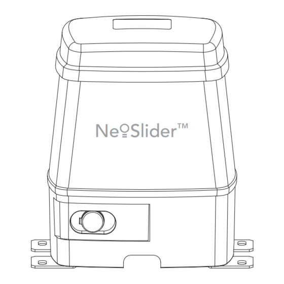
- Page 1 NES-24V1 NeoSlider™ Sliding Gate Opener Ne Slider ™ Featuring TrioCode ™ Technology Part # 13311 Manual v1.00 INSTALLATION INSTRUCTIONS | OWNERS COPY...
- Page 2 Automatic Technology Australia Pty Ltd to the extent that such may be lawfully excluded hereby expressly disclaims all conditions or warranties, statutory or otherwise which may be implied by laws as conditions or warranties of purchase of an Automatic Technology Australia Pty Ltd Sliding Gate Opener.
-
Page 3: Table Of Contents
™ NeoSlider Sliding Gate Opener NES-24V1 Important Safety Instructions Features Product Description Drive Unit Installation Rack Installation Limit Actuator Installation Control Board Layout Menu Structure Powering Up Drive Unit Setting Travel Limits Reprofi le Travel Setting Pedestrian Position Standard Operating Modes Remote Code Set Procedure Control Board Adjustments Diagnostic Tools (menu 8) -
Page 4: Important Safety Instructions
(PE ) Beam. In most countries, PE Beams are mandatory on all gates fi tted with automatic openers. For a small additional outlay, Automatic Technology recommends that Photo Electric Beams be installed with the automatic opener ensuring additional safety and peace of mind. - Page 5 Important Safety Instructions Please read this instruction manual fully before attempting to install or use the opener. Failure to comply with the installation instructions may result in serious injury and/or property damage. The opener is showerproof - it should not be immersed in water or sprayed directly by a hose or other water carrying device.
-
Page 6: Features
Features Thank purchasing NES-24V1 NeoSlider™ from Automatic Technology. Designed for residential sliding gates by our world renowned team of engineers, this unit will give years of smart, simple and secure operation. Listed below are some of its many features. Operation To activate the gate simply press a button on the TrioCode®... - Page 7 ISS (Intelligent Safety System) Should the gate hit an obstacle while it is performing a close cycle, or be restricted in some manner, it will automatically reverse. The amount of force the gate should encounter before reversing is automatically adjusted by the control system during the initialisation of the automatic opener.
-
Page 8: Product Description
Product Description The Automatic Technology NeoSlider™ sliding gate opener kit consists of one (1) drive unit with integrated controller, two (2) handheld PTX-5 TrioCode® transmitters, a pre-wired antenna ready for mounting on the fence-line and two (2) limits actuators. (Fig. 01). - Page 9 1. Prior to mounting the NeoSlider™, determine the distance from the gate to the outer edge of the rack (i.e. the rack width) and to the datum line (see Fig. 03 and Fig. 04). If using an Automatic Technology plastic rack, the width is 40mm.
-
Page 10: Rack Installation
Rack Installation Rack width Gate fi g Rack Drive gear Datum line Mounting rack to gate A strong base on the gate is required for mounting the rack. 1. Manually open the gate and place a rack section to mesh with the pinion gear on the Drive Unit. Mark the top of the rack. -
Page 11: Limit Actuator Installation
Limit Actuators Installation M4 x 10 w/washer screws fi g Mounting holes Actuator mounting block M4 x 30 screws Fixing limit actuator to rack 1. Manually open the gate to the open position and mark this on the gate rack under the actuating arm. 2. -
Page 12: Control Board Layout
Control Board Layout 24VDC output for powering accessories 3A(max) Light relay driver Lock relay driver P.E input terminal COM terminal for inputs terminals 6 - 11 OPN N/O input terminal STP N/O input terminal CLS N/O input terminal OSC N/O input terminal SWP N/O input terminal PED N/O input terminal Engage sensor microswith input... - Page 13 Control Board Layout 24VAC MOTOR FUSE fi g DCB02-2XX ENGAGED Owner Installation Instructions NeoSlider™ - Sliding Gate Opener NES-24V1...
-
Page 14: Menu Structure
Menu Structure NeoSlider™ - Sliding Gate Opener NES-24V1 Owner Installation Instructions... - Page 15 Initial Electrical Installation CAUTION: Cables which have a green/yellow coloured insulation are for earthing purposes only. Never use these cables for any other purpose. Warning: A qualifi ed electrician must perform the installation where 240V AC power is used. Owner Installation Instructions NeoSlider™...
-
Page 16: Powering Up Drive Unit
Powering Up The Drive Unit Installing antenna Start up screen Mount the antenna at or above the height of the gate or fence (whichever is higher) for optimal reception. Do A.T.A N N ES-24V1 not cut the coaxial cable. Firmware #.## PLEASE NOTE - Before plugging the NeoSlider™... - Page 17 Setting Travel Limits (Cont.) Step 3. Setting close travel limit 1. Press and hold the CLOSE button (or press button 4 on the transmitter) until the gate reaches the close DRIVE MTR CLOSE position, i.e. when the rail-mounted actuator pushes PRESS SET the microswitch to the close position (Fig.
-
Page 18: Reprofi Le Travel
Reprofi le Travel Recalculate Force Margins Reprofi ling is a simplifi ed way of re-learning the travel characteristic of a previously setup Limit Switch travel installation. Re-profi ling can be used when the travel characteristics of the gate change due to mechanical adjustments etc. -
Page 19: Standard Operating Modes
Standard Operating Modes This section describes the standard operation of the Pedestrian access (PED) function control board with the factory set default values. (Activated by PED terminal with N/O switch or by transmitter button with PED function Motor control assigned). The pedestrian access operation opens the gate partially to allow pedestrian The controller drives the motor in the direction access but prevent vehicle access. -
Page 20: Control Board Adjustments
The timer then counts down and when it expires, the controller starts to close the gate. Details of the four Auto-Close modes are outlined below. Automatic Technology strongly recommend using a PE Beam for added safety. Standard Auto-Close... -
Page 21: Menu 4 Lock Times
Control Board Adjustments Menu 4. Lock times Lock output can be programmed for both hold and pulse motor starting. The operation of the lock can be programmed to activate prior to the gate and behave differently on open and close cycles. Parameter Default Step... -
Page 22: Menu 7 Operating Modes
Activity report ID of three modes: This parameter sets the ID of the controller that is sent with the activity report. Contact Automatic Technology 1. Open and close cycles stop for more details. In this mode all cycles are prevented from being... -
Page 23: Viewing And Editing Parameters
Viewing And Editing Parameters This section illustrates how to locate, view and adjust View Mode (No cursor) parameters. Parameter name Parameter number in list Locating parameters Refer to MENU STRUCTURE on Page 14 or the preceding section for CONTROL BOARD ADJUSTMENTS. Locate Parameter the required parameter and note the MENU number. -
Page 24: Coding Transmitter
The fi rst memory location sets the type of transmitters which can be stored into the memory of the receiver. It either can be Automatic Technology TrioCode™ or B&D Tri-Tran™ transmitters. For example, if fi rst transmitter stored is TrioCode™ then the rest of the transmitters can only be the TrioCode™... -
Page 25: Transmitter Editing
Coding Transmitter Returning to main screen The “Code Transmitter” menu will now be shown. Press EXIT to return to the MAIN SCREEN and test the transmitter. fi g NOTE: To edit the other settings, refer to Transmitter editing. Transmitter editing Display transmitter record Using one of the methods below, display the required transmitters details. - Page 26 Coding Transmitter Step 3. Editing the store location This feature is only available when coding the fi rst button of a new transmitter. 1. Press NEXT or PREV to move cursor over Store No. fi g 2. Press UP or DOWN to select new Store No (Fig. 26). 3.
-
Page 27: Transmitter Management
Transmitter Management The NeoSlider™ provides a transmitter listing facility which enables the user to fi nd a transmitter location within the memory. Once located, a stored transmitter can be replaced, deleted, edited, copied or, if the fi g location is empty, a new transmitter can be coded. Method 1 - Go to the start of the list Step 1. -
Page 28: Code Operation (Location Empty)
Transmitter Management Step 2. Navigating the list 1. Press UP or DOWN buttons to navigate through the list (Fig. 38). 2. Press SET to display menu of available functions. fi g NOTE: Holding a button down will step through the list faster. -
Page 29: Remote Code Set Procedure
Remote Code Set Procedure If a transmitter is already coded into the opener, Existing additional transmitters can be coded without being in transmitter direct contact with the gate opener. PRESS NOTE: Only the function of the existing transmitter button can be assigned to a new transmitter. Please read instructions prior to proceeding - there is a time- out facility for security reasons. -
Page 30: Diagnostic Tools (Menu 8)
Diagnostic Tools The controller provides several diagnostic tools from within the diagnostics menu (menu 8). This section details the function of each tool and its use. fi g Navigating to diagnostics menu 1. Press PREV to navigate to Menu 8 (Fig. 46). 2. -
Page 31: Menu 8.5 Service Counter
Menu 8.5 Service counter The opener provides a periodic service counter which can be set to expire after a number of drive cycles. When expired, the opener will beep at the beginning fi g of each drive cycle and a message will be displayed on the MAIN SCREEN (Fig. -
Page 32: Memory Tools (Menu 9)
Memory Tools The Memory Tools accessed from within Menu 9 are used to clear the memory of the controller. Once selected, the PREV or NEXT buttons can be used to view the Memory Tool options. To execute the displayed option simply press SET. fi... -
Page 33: Accessories Installation
Accessories Installation Photo Electric (PE) Beams A photo electric (PE) Beams extends across the gate opening. This photo electric (PE) Beams is designed to detect an obstruction while the gate is closing and to send a signal to the gate opener to reverse or stop the gate movement. -
Page 34: Troubleshooting Guide
In such an instance please contact your Automatic Technology dealer for an alternative frequency replacement kit. As this is not a warrantable situation but an environmental issue, charges may apply for the changeover. -
Page 35: Specifi Cations
2. The fi rst memory location sets the type of transmitters which can be stored into the receivers memory. It can be either Automatic Technology TrioCode™ or B&D Tri-Tran™ transmitters. 3. Intermittent operations may occur in areas which experience very strong wind gusts. A strong wind puts extra pressure on the gate and tracks which may in turn trigger the safety obstruction detection system intermittently. -
Page 36: Parts List
Parts List When ordering spare parts please quote the order code number to your installer/dealer. 41. Power cord 1.5m W2PIN + 1R 14150 Item/description order code 1. Base 62400 42. Pan head screw M2.5 x 10 10375 2. Mounting bracket ext 62502 43. - Page 37 Owner Installation Instructions NeoSlider™ - Sliding Gate Opener NES-24V1...
-
Page 38: Warranty
Trade Practices Act 1974 (Cth). 2. Subject to all of the matters set out below, Automatic Technology Australia Pty Ltd (“ATA”) warrants: (a) swing and sliding gate opener drive units for twelve (12) months or 2500 cycles, whichever occurs fi rst;... -
Page 39: Notes And Record
Notes And Record Purchased from: Phone: Installed by: Date: Serial No: Owner Installation Instructions NeoSlider™ - Sliding Gate Opener NES-24V1... - Page 40 © August 2009 Automatic Technology (Australia) Pty Ltd. All rights reserved. NeoSlider™ and TrioCode™ are the trademarks of Automatic Technology (Australia) Pty Ltd. Tri-Tran™ is a trademark of B&D Doors and openers. No part of this document may be reproduced without prior permission. In an ongoing commitment to product quality we reserve the right to change specifi...
Need help?
Do you have a question about the NES-24V1 NeoSlider and is the answer not in the manual?
Questions and answers