
Related Manuals for Automatic Technology DCB-05


Summary of Contents for Automatic Technology DCB-05
- Page 1 Dual Gate Controller 24 Volt Gate Control System DCB-05 ™ Featuring TrioCode Technology Part # 13253 (Manual v1.00)
- Page 2 Automatic Technology Australia Pty Ltd to the extent that such may be lawfully excluded hereby expressly disclaims all conditions or warranties, statutory or otherwise which may be implied by laws as conditions or warranties of purchase of...
-
Page 3: Table Of Contents
Dual gate controller 24 volt gate control system DCB-05 Important safety instructions Features Control board layout Menu structure Initial electrical installation Powering up drive unit Setting travel limits Standard Operating Modes Control board adjustments Menu 2 current trips Menu 3 Auto-close times... -
Page 4: Important Safety Instructions
FOR ADDITIONAL SAFETY protection we strongly recommend the fi tting of a Photo Electric (PE) Beam. In most countries PE Beams are mandatory on all gates fi tted with automatic openers. For a small additional outlay Automatic Technology recommends that Photo Electric Beams be installed with the automatic opener ensuring additional safety and peace of mind. - Page 5 The gate controller is not intended for use by young children or infi rm persons without adequate supervision. Children should be supervised to ensure that they do not play with the remote transmitters or the opener. Owner Installation Instructions Dual Gate Controller DCB-05...
-
Page 6: Features
Features Thank you for purchasing the automatic Dual Gate Controller from Automatic Technology. Designed for residential 24 volt swing and sliding gates by our world renowned team of engineers, this unit will give years of smart, simple and secure operation. Listed below are some of the many features. - Page 7 Smart Solar ™ and Battery Backup Compatibility The Dual Gate Controller can be fi tted with optional Smart Solar™ or Battery Backup kit to provide operation during power outages or at unpowered sites. Owner Installation Instructions Dual Gate Controller DCB-05...
-
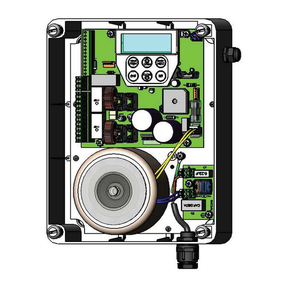
Page 8: Control Board Layout
MOTOR 2 open limit switch input terminal COM terminal for Terminals 16,17,19 & 20. MOTOR 1 close limit switch input terminal MOTOR 1 open limit switch input terminal MOTOR 1 terminal 1 MOTOR 1 terminal 2 Dual Gate Controller DCB-05 Owner Installation Instructions... - Page 9 Control board layout fi g Owner Installation Instructions Dual Gate Controller DCB-05...
-
Page 10: Menu Structure
Menu structure Dual Gate Controller DCB-05 Owner Installation Instructions... -
Page 11: Initial Electrical Installation
MOTOR 1 CLOSE LIMIT SWITCH INPUT MOTOR 1 OPEN LIMIT SWITCH INPUT MOTOR 1 CONNECTOR 1 MOTOR 1 CONNECTOR 2 24 VOLTS DC OUTPUT PLUS (+) MOTOR 1 24 VOLTS DC OUTPUT MINUS (-) Owner Installation Instructions Dual Gate Controller DCB-05... -
Page 12: Powering Up Drive Unit
To navigate to the Menu 10.1 from the main screen simply press PREV to display MENU 10, followed by SET PREV NEXT to display MENU 10.1. Press SET again to start the limit setting procedure Fig. 07. EXIT PRESS Dual Gate Controller DCB-05 Owner Installation Instructions... - Page 13 When the setup is complete Open Limit,Set the MAIN SCREEN will be displayed with the gate fi g shown to be OPEN. The Gate can now be used. PRESS PREV NEXT EXIT Owner Installation Instructions Dual Gate Controller DCB-05...
- Page 14 “MENU 10.3 Re-profi le Travel” and press SET then follow the prompts. The re-profi le feature will also be automatically started when a control parameter is altered which affects the gates travel. Re-profi le is not available for TIMED TRAVEL installations. Dual Gate Controller DCB-05 Owner Installation Instructions...
- Page 15 Press SET to set the travel times by actually driving the motor(s) or press EXIT to enter PREV NEXT EXIT PRESS Selecting install method SET=Drive Motors EXIT=Enter times fi g PREV NEXT EXIT Owner Installation Instructions Dual Gate Controller DCB-05...
- Page 16 SET Fig. 29 and the main screen with be displayed and the gate is ready to be used. EXIT Confi rming Settings Save Settings? fi g PREV NEXT EXIT PRESS Dual Gate Controller DCB-05 Owner Installation Instructions...
-
Page 17: Standard Operating Modes
If the gate is stopped, the OSC input will cause the gate to move in the opposite direction to that last travelled. If the gate is moving the OSC input will cause the gate to stop. Owner Installation Instructions Dual Gate Controller DCB-05... - Page 18 (from closed). The setting is accessed from “MENU 10.4 Set Pedestrian”. The time is adjustable in 1 second steps. Dual Gate Controller DCB-05 Owner Installation Instructions...
-
Page 19: Control Board Adjustments
AMPS detection current Maximum startup amps sets maximum permitted AMPS starting current of motors Parameter (timed travel) Default Step Unit Menu No. Cutout AMPS maximum motor current permitted after 10.0 10.0 AMPS startup Owner Installation Instructions Dual Gate Controller DCB-05... -
Page 20: Menu 3 Auto-Close Times
The timer then counts down and when it expires the controller starts to close the gate. Details of the four Auto-Close modes are outlined below. Automatic Technology strongly recommend using a PE Beam for added safety. Standard Auto-Close... -
Page 21: Menu 4 Lock Times
LIMIT SWITCH/AMP TRAVEL installations. The value calculated is selected so that the delay between M2 and M1 reaching the close position is equal to the OPEN SYNC DELAY TIME. The MAX OVERRUN TIME is set to 0 for TIMED TRAVEL installations. Owner Installation Instructions Dual Gate Controller DCB-05... -
Page 22: Menu 7 Operating Modes
In this mode, the PE input has no effect when feature. This parameter can be used to disable the opening but will stop the gate when closing. feature for security or transmitter management reasons. Dual Gate Controller DCB-05 Owner Installation Instructions... - Page 23 7.10 Selects function of OUTPUT1 and OUTPUT2 LOCK LIGHT LOCK OUTPUT2= OUTPUT2= OUTPUT2= LIGHT LOCK LIGHT OPN INPUT = 2ND PE 7.11 Open input acts as 2nd PE input FAULT AUTO RESET 7.12 Owner Installation Instructions Dual Gate Controller DCB-05...
-
Page 24: Viewing And Editing Parameters
If the parameter values are not to be changed, press Default?” screen, giving option of Exits back to View Mode EXIT to return to sub menu. Press EXIT again to return loading default value with no changes made to the MAIN SCREEN. Dual Gate Controller DCB-05 Owner Installation Instructions... -
Page 25: Transmitter Overview
Press SET to save the settings (Fig. 37) or EXIT to abort without saving. EXIT PRESS Returning to main screen The “Code Transmitter” menu will now be shown. Press EXIT to return to the MAIN SCREEN and test the transmitter. Owner Installation Instructions Dual Gate Controller DCB-05... -
Page 26: Transmitter Editing
NOTE: If all button functions are set to OFF, when SET is pressed, the opener will prompt to confi rm if EXIT the transmitter is to be deleted. Press SET to delete or EXIT to continue editing. Dual Gate Controller DCB-05 Owner Installation Instructions... - Page 27 4. Repeat step 2. 5. Press SET to record changes (Fig. 43). The second line of the display shows a list of available characters with the current value indicated at the cursor position. Owner Installation Instructions Dual Gate Controller DCB-05...
-
Page 28: Transmitter Management
NOTE: “VIEW>” will not be shown if the transmitter is fi g not stored. PREV NEXT EXIT PRESS Press Tx’er PRESS Button! LIST> fi g PREV NEXT EXIT Press Tx’er Again! View> fi g PRESS PREV NEXT EXIT Dual Gate Controller DCB-05 Owner Installation Instructions... -
Page 29: Code Operation (Location Empty)
CODE TRANSMITTER PROCEDURE for each transmitter EXIT to be coded. Coding is terminated by pressing the EXIT button. Exiting the list To exit the transmitter list simply press EXIT to return to the Code. Owner Installation Instructions Dual Gate Controller DCB-05... -
Page 30: Remote Code Set Procedure
ID label of the new transmitter is set to: R/C Tx ###, where ### is the existing transmitters store number. This ensures that the originator of any remote coded transmitter transmitter can be identifi ed. PRESS fi g Dual Gate Controller DCB-05 Owner Installation Instructions... -
Page 31: Diagnostic Tools (Menu 8)
Memory Tools viewing the events, press EXIT. fi g Menu 8.4 Memory usage PREV NEXT This tool displays the number of transmitter store EXIT PRESS location used and the number free (Fig. 63). Owner Installation Instructions Dual Gate Controller DCB-05... -
Page 32: Menu 8.5 Service Counter
10: M1 Open Obstructions 11: M1 Close Obstructions 12: M1 Open Overloads 13: M1 Close Overloads 14: M1 PWM Sync Faults 15: M1 PWM Drive Faults 16: M1 Direction Faults 17: M1 Sensor Faults Dual Gate Controller DCB-05 Owner Installation Instructions... -
Page 33: Memory Tools (Menu 9)
This option is provided so that transmitter labels entered using Transmitter Management software on a P.C can be loaded into memory without altering the transmitters themselves. Owner Installation Instructions Dual Gate Controller DCB-05... -
Page 34: Setting Pedestrian Position
Step 2. Setting pedestrian position 1. Press OPEN or CLOSE to adjust pedestrian drive time. 2. Press SET to record position 3. Press transmitter coded for pedestrian function or push button wired into pedestrian input to test. Dual Gate Controller DCB-05 Owner Installation Instructions... -
Page 35: Accessories Installation
Connect the OUT1 N/C light as per the diagram at right (Fig. 69). OUT1 COMMON OUT1 N/O fi g WARNING: A qualifi ed electrician must perform the installation where 240V AC power is used. Owner Installation Instructions Dual Gate Controller DCB-05... - Page 36 If gate stops or moves very slowly under battery power, the batteries may be weak or have no charge. Connect mains power and allow the batteries to charge. This may take 24 - 48 hours to reach maximum charge capacity. Dual Gate Controller DCB-05 Owner Installation Instructions...
-
Page 37: Specifi Cations
ATA TrioCode™ or B&D Tri-Tran™ transmitters. 2. The storage memory can be increased from 30 transmitters to 511. Contact ATA for details. NOTE: Specifi cations are subject to change without notice. Owner Installation Instructions Dual Gate Controller DCB-05... -
Page 38: Notes And Record
Notes and record Purchased from: Phone: Installed by: Date: Serial No: Dual Gate Controller DCB-05 Owner Installation Instructions... -
Page 39: Warranty And Exclusion Of Liability
Trade Practices Act 1974 (Cth). 2. Subject to all of the matters set out below, Automatic Technology Australia Pty Ltd (“ATA”) warrants: (a) swing and sliding gate opener drive units for twelve (12) months or 2500 cycles, whichever occurs fi rst;... - Page 40 © October 2008 Automatic Technology (Australia) Pty Ltd. All rights reserved. TrioCode™ is a trademark of Automatic Technology (Australia) Pty Ltd. No part of this document may be reproduced without prior permission. In an ongoing commitment to product quality we reserve the right to change specifi cation without notice. E&OE.
Need help?
Do you have a question about the DCB-05 and is the answer not in the manual?
Questions and answers