
Related Manuals for Yamaha Scorpio


Summary of Contents for Yamaha Scorpio
- Page 1 SCORPIO ( SX-4 ) SERVICEMANUAL a Winanda Fairyanto's collection nanda@jogjalandrover.org fairyanto@gmail.com yamaha_scorpio@yahoogroups.com 5BP-F8197-B0...
- Page 2 SERVICE MANUAL SCORPIO © 2006 oleh Yamaha Motor Co., Ltd. Edisi kedua, Agustus 2006 dialih bahasakan oleh : Technical Publication Yamaha Indonesia Motor Manufacturing di cetak di Indonesia...
-
Page 3: Spesifikasi
PENDAHULUAN Service Manual ini dibuat oleh Yamaha Motor Company, Ltd. dan dialih bahasakan oleh, Technical Publication Yamaha Indonesia diharapkan dapat dipakai oleh Teknisi Bengkel dan Dealer Yamaha Kami menyadari bahwa tidak mungkin menjelaskan seluruh pelajaran teknik perbaikan sepeda motor dalam satu buku saja. sehingga kami meyarankan kepada para mekanik harus terlebih dahulu menguasai dasar-dasar perbaikan sepeda motor Yamaha dengan mengikuti training-training reguler yang diadakan oleh Yamaha. - Page 4 TEKNIK MEMBACA CEPAT BUKU PETUNJUK SUSUNAN BUKU PETUNJUK Buku ini terdiri dari beberapa BAB utama yang didalamnya terdapat beberapa judul (lihat "simbol") Judul pertama 1: BAB yang disertai simbol, terletak disudut kanan atas, pada setiap halaman. Judul kedua 2: Judul ini adalah judul bagian BAB yang terletak hanya pada halaman pertama dari tiap-tiap bagian, judul ini terletak disudut kiri atas halaman Judul ketiga 3: Judul ini adalah judul yang lebih spesifik.
- Page 5 SIMBOL (sesuai illustrasi) SPEC INFO Illustrasi simbol 1 hingga 8 merupakan simbol di setiap BAB, yang menggambarkan isi dari setiap BAB. INSP 1 Informasi Umum 2 Spesifikasi 3 Perawatan berkala dan pelumasan 4 Membongkar mesin 5 Karburator 6 Rangka/Chassis CHAS CARB 7 Kelistrikan/Electrical 8 Cara mengatasi masalah/Troubleshooting...
-
Page 6: Daftar Isi
DAFTAR ISI INFORMASI UMUM INFO SPESIFIKASI SPEC PERAWATAN BERKALA DAN INSP PENYETELAN MEMBONGKAR MESIN CARBURATOR CARB RANGKA/CHASSIS CHAS – KELISTRIKAN ELEC TROUBLESHOOTING TRBL SHTG... -
Page 7: Table Of Contents
INFO BAB 1. INFORMASI UMUM IDENTIFIKASI SEPEDA MOTOR ............... 1-1 NOMOR RANGKA ................1-1 NOMOR MESIN ..................1-1 INFORMASI PENTING ................. 1-2 PROSEDUR PERSIAPAN MEMBONGKAR ......... 1-2 PART PENGGANTI ................1-2 GASKETS, OIL SEALS DAN O-RINGS ..........1-2 LOCK WASHERS/PLATES DAN COTTER PINS ......... 1-3 BEARING DAN SEAL OIL .............. - Page 8 INFO...
-
Page 9: Informasi Umum
IDENTIFIKASI SEPEDA MOTOR INFO YP100000 INFORMASI UMUM IDENTIFIKASI SEPEDA MOTOR YP100020 NOMOR RANGKA/CHASIS Nomor rangka 1 tercetak pada rangka di bagian down tube EB100030 NOMOR MESIN Nomor mesin (2) tercetak pada crankcase mesin sebelah kanan. CATATAN: bentuk dan spesifikasi sewaktu-waktu dapat berubah tanpa pemberitahuan. -
Page 10: Informasi Penting
6. Jaga semua komponern dari pengaruh panas. EB101010 PART PENGGANTI 1. Pergunakan hanya spare part asli Yamaha/ genuine part. pergunakan juga oli dan gemuk yang disarankan Yamaha untuk pelumasan. Komponen imitasi, terlihat sama dengan yang asli, tetapi kualitasnya jauh lebih buruk. -
Page 11: Lock Washers/Plates Dan Cotter Pins
INFORMASI PENTING INFO EB101030 LOCK WASHERS/PLATES DAN COTTER PINS 1. Ganti lock washers/plates dan cotter pin setelah dibuka. Tekuk lock washer plat, di bagian yang rata pada bagian Mur, setelah mur dikencang- sesuai spesifikasi pengencangan. EB101040 BEARING DAN SEAL OIL Pasang bearing dan seal oli dengan posisi marking berada di luar. - Page 12 INFORMASI PENTING INFO EB801000 MEMERIKSA SISTIM PENYAMBUNGAN Bersihkan debu dan kotoran yang terdapat pada pada connector. 1. Lepaskan: • Connector 2. Semprot dengan udara bertekanan. 3. Pasang dan cabut connector dua atau tiga kali pemasangan 4. Tarik kabel untuk memeriksa, agar kabel tidak tercabut, terlepas.
-
Page 13: Special Tools
SPECIAL TOOLS INFO EB102000 SPECIAL TOOLS The following special tools are necessary for complete and accurate tune-up and assembly. Use only the appropriate special tools; this will help prevent damage caused by the use of inappropriate tools or improvised techniques. When placing an order, refer to the list provided below to avoid any mistakes Nomor tool Nama tool... - Page 14 SPECIAL TOOLS INFO Nomor Tool. Nama Tool Gambar Illustrasi Flywheel puller 90890-01362 Alat ini digunakan untuk melepas magnet Fork seal driver weight Fork seal driver attachment (ø33) Weight 90890-01367 Attachment 90890-01368 Alat ini digunakan untuk memasang seal oli dan seal debu pada fork depan. Steering nut wrench 90890-01403 Alat ini digunakan untuk mengencangkan,...
- Page 15 SPECIAL TOOLS INFO Nomor Tool Nama Tool Gambar Illustrasi Universal clutch holder 90890-04086 Alat ini digunakan untuk menahan clutch boss, pada saat memasang dan melepas baut clutch boss nut. Ignition checker 90890-06754 Alat ini digunakan untuk memeriksa komponen sistim pengapian. 1 - 7...
- Page 16 SPEC BAB 2. SPESIFIKASI SPESIFIKASI UMUM ................. 2-1 SPESIFIKASI PERAWATAN ..............2-4 MESIN ....................2-4 RANGKA/CHASSIS ................2-12 KELISTRIKAN ..................2-15 SPESIFIKASI TORSI UMUM ..............2-17 UNIT SATUAN .................... 2-17 POIN PELUMASAN DAN TIPE PELUMAS YANG DIPAKAI ....2-18 MESIN ....................2-18 RANGKA/CHASSIS ................
- Page 17 SPEC...
-
Page 18: Spesifikasi Umum
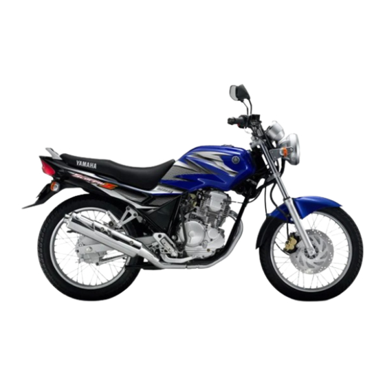
SPEC SPESIFIKASI UMUM SPESIFIKASI SPESIFIKASI UMUM Model SX-4 Kode model : 5BP1 Dimensi: Panjang 2.020 mm Lebar 770 mm Tinggi 1.090 mm Tinggi tempat duduk 770 mm Jarak sumbu roda 1.295 mm Jarak ketanah 165 mm Berat: Dengan Oli dan bahan bakar terisi penuh 131 kg Kemampuan berbelok : 2.100 mm... - Page 19 SPEC SPESIFIKASI UMUM Model SX-4 Busi : Tipe/pabrik pembuat D8EA/NGK atau X24ES-U/DENSO 0.6 ~ 0.7 mm Tipe kopling : Basah, multiple-disc Transmisi : Sistim reduksi Primary Spur gear Perbandingan reduksi primary 74/24 (3.083) Sistim reduksi secondary Rantai penggerak Perbandingan reduksi secondary 44/15 (2.933) Tipe Transmission Constant mesh, 5-kecepatan...
-
Page 20: General Specifications
SPEC GENERAL SPECIFICATIONS Model SX-4 Shock absorber: Front shock absorber Coil spring, oil damper Rear shock absorber Coil spring, oil damper Wheel travel: Front wheel travel 140 mm Rear wheel travel 100 mm Electrical: Ignition system Generator system A.C. magneto generator Battery type or model GM7B-4B Battery capacity... -
Page 21: Maintenance Specifications
SPEC MAINTENANCE SPECIFICATIONS MAINTENANCE SPECIFICATIONS ENGINE Model SX-4 Cylinder head: Warp limit <0.03 mm> Lines indicate straight edge measurement. Cylinder: Bore size/measuring point 70.000 ~ 70.018 mm 40 mm Wear limit <0.01 mm> Camshaft: Drive method Chain drive (right) Camshaft outside dia. 24.96 ~ 24.98 mm Cam dimensions: Intake:... - Page 22 SPEC MAINTENANCE SPECIFICATIONS Model SX-4 Value dimensions: “A” head dia. 33.9 ~ 34.1 mm 28.4 ~ 28.6 mm “B” face width 2.26 mm 2.26 mm “C” seat width 0.9 ~ 1.1 mm 0.9 ~ 1.1 mm “D” margin thickness 0.8 ~ 1.2 mm 0.8 ~ 1.2 mm Stem outside dia.
- Page 23 SPEC MAINTENANCE SPECIFICATIONS Model SX-4 Tilt limit <2.5°/1.6 mm> <2.5°/1.6 mm> Direction of winding Inner Counterclockwise Counterclockwise Outer Clockwise Clockwise Piston: Piston-to-cylinder clearance 0.020 ~ 0.025 mm <Limit> <0.05 mm> Piston size “D” 69.977 ~ 69.996 mm Measuring point “H” 4 mm Piston ring: Top ring:...
- Page 24 SPEC MAINTENANCE SPECIFICATIONS Model SX-4 Crankshaft: Crank width “A” 69.25 ~ 69.30 mm Runout limit “B” <0.03 mm> Big end side clearance “C” 0.35 ~ 0.85 mm Clutch: Friction plate: Thickness 2.9 ~ 3.1 mm Quantity 6 pcs. Wear limit <2.8 mm>...
- Page 25 SPEC MAINTENANCE SPECIFICATIONS Model SX-4 Fuel level 2.7 ~ 4.7 mm below the float chamber line Engine idling speed 1,350 ~ 1,450 r/min Lubrication system: Oil filter type Paper and wire mesh type Oil pump type: Trochoid type Tip clearance 0.15 mm Side clearance 0.04 ~ 0.09 mm...
-
Page 26: Lubrication Chart
SPEC MAINTENANCE SPECIFICATIONS Model SX-4 Lubrication chart: OIL CLEANER PIN WITH CYLINDER HEAD HOLE DRIVE AXLE MAIN AXLE OIL PUMP CRANKSHAFT CAMSHAFT OIL STRAINER OIL PAN 2 - 9... - Page 27 SPEC MAINTENANCE SPECIFICATIONS Tightening torque Tightening Thread torque Part to be tightened Part name Q’ty Remarks size m·kg Camshaft sprocket cover Bolt Tappet cover Bolt Cylinder head Flange bolt Bolt Cylinder head (exhaust pipe) Stud bolt Cylinder head bearing plate Bolt Cylinder head breather plate Bolt...
- Page 28 SPEC MAINTENANCE SPECIFICATIONS Tightening Thread torque Part to be tightened Part name Q’ty Remarks size m·kg Pickup coil Bolt Starter motor Bolt Kick crank Bolt Kick racket wheel guide Bolt Use lock washer 2 - 11...
- Page 29 Oil capacity 252 cm Oil level 95 mm From top of fully compressed inner tube without fork spring Oil grade Yamaha fork oil 10W or equivalent Rear suspension: Shock absorber travel 32 mm Spring rate: 16.01 kg/mm Stroke: 0 ~ 32 mm...
- Page 30 SPEC MAINTENANCE SPECIFICATIONS Item SX-4 Front disc brake: Disc brake type Single Disc outside diameter × thickness 267 × 4 <Limit> <3.5 mm> Brake pad lining thickness 5.3 mm <Limit> <0.8 mm> Master cylinder inside diameter 11 mm Caliper cylinder inside diameter 26.99 mm 22.22 mm Recommended fluid...
- Page 31 SPEC MAINTENANCE SPECIFICATIONS Tightening torque Tightening torque Part to be tightened Thread size Remarks m·kg M8 × 1.25 Handle crown and inner tube M22 × 1.0 Handle crown and steering stem 11.0 Steering stem and ring nut – 1.8 See NOTE M8 ×...
- Page 32 248 ~ 372 Ω at 20°C Pickup coil resistance (color) (Red - White) 688 ~ 1,032 Ω at 20°C Source coil resistance (Brown - Green) CDI. unit-model/manufacturer 5BP/YAMAHA Ignition coil: Model/manufacturer 5BP/YAMAHA 0.32 ~ 0.48 Ω at 20°C Primary winding resistance Secondary winding resistance 5.68 ~ 8.52 kΩ...
- Page 33 SPEC MAINTENANCE SPECIFICATIONS Item SX-4 Horn: Plain type × 2 Type/quantity Model/manufacturer 5BP/IMASEN Maximum amperage 1.5 A Flasher relay: Type Condenser type Model/manufacturer 3RS/DENSO Self cancelling device Flasher frequency 75 ~ 95 cycle/min 10 W × 2 + 3.4 W Wattage Starting circuit cut-off relay: Model/manufacturer...
-
Page 34: General Torque Specifications
GENERAL TORQUE SPECIFICATIONS/ SPEC DEFINITION OF UNITS GENERAL TORQUE SPECIFICATIONS This chart specifies torque for standard fasten- General torque ers with standard I.S.O. pitch threads. specifications (Nut) (Bolt) Torque specifications for special components m·kg ft·lb or assemblies are included in the applicable 10 mm 6 mm sections of this book. - Page 35 Primary driven gear Engine oil Push lever axle Molybdeum disulfide oil Transmission gear (wheel/pinion) Molybdeum disulfide oil Axle (main/drive) Molybdeum disulfide oil Shift cam Molybdeum disulfide oil Shift fork/guide bar Engine oil ® Crankcase mating surfaces Yamaha bond No.1215 2 - 18...
- Page 36 SPEC LUBRICATION POINTS AND LUBRICANT TYPE CHASSIS Lubrication Symbol Lubricant type Steering bearing (upper/lower) Lithium-soap base grease Wheel bearing/axle Lithium-soap base grease Front wheel oil seal (right/left) Lithium-soap base grease Rear wheel oil seal Lithium-soap base grease Clutch hub oil seal Lithium-soap base grease Clutch hub fitting area Lithium-soap base grease...
-
Page 37: Cable Routing
SPEC CABLE ROUTING CABLE ROUTING 1 Tachometer cable A Fuel sender lead È Clamp the wire harness. 2 Brake hose B Breather hose É Pass the cable holder through 3 Brake hose holder C Air vent hose the tachometer cable. 4 Wire harness D Throttle cable Ê... - Page 38 SPEC CABLE ROUTING Î To fuel tank Ï Clamp the throttle cable and clutch cable. Turn the clamp end to inside of motorcycle. Ð Clamp the throttle cable and clutch cable. Ñ Insert the air vent hose into the frame. Ò...
- Page 39 SPEC CABLE ROUTING 1 Clutch cable B Fuel tank over flow hose Ë Clamp the magneto lead and 2 Breather hose pick-up coil lead. 3 Fuel tank over flow hose È Install the horn lead (long side) Ì Clamp the battery breather 4 Magneto lead to the left side of the horn hose.
- Page 40 2 - 23...
- Page 41 INSP BAB 3. PARAWATAN BERKALA DAN PENYETELAN PENDAHULUAN ................... 3-1 PERAWATAN BERKALA/PELUMASAN ............ 3-1 TEMPAT DUDUK/JOK ................. 3-3 PENUTUP SAMPING/SIDE COVER ............3-3 TANGKI BENSIN ..................3-3 MESIN ......................3-4 MENYETEL KELONGGARAN KLEP ............ 3-4 MENYETEL PUTARAN LANGSAM ......3-5 ..MENYETL GAS.
- Page 42 INSP ELECTRICAL ..................... 3-28 BATTERY INSPECTION ..............3-28 FUSE INSPECTION ................3-31 HEADLIGHT BEAM ADJUSTMENT ........... 3-32 HEADLIGHT BULB REPLACEMENT ..........3-32...
-
Page 43: Periodic Inspection And Adjustment
INSP INTRODUCTION/PERIODIC MAINTENANCE/ LUBRICATION PERIODIC INSPECTION AND ADJUSTMENT INTRODUCTION This chapter includes all information necessary to perform recommended inspections and adjust- ments. These preventive maintenance procedures, if followed, will ensure more reliable vehicle operation and a longer service life. The need for costly overhaul work will be greatly reduced. This information applies to vehicles already in service as well as new vehicles that are being prepared for sale. - Page 44 • Adjust headlight beam. *Since these items require special tools, data and technical skills, have a Yamaha dealer perform the service. NOTE: The air filter needs more frequent service if you are riding in unusually wet or dusty areas.
-
Page 45: Penutup Samping/Side Cover
INSP SEAT/SIDE COVER/FUEL TANK SEAT 1.Install: Seat 1 NOTE: Insert the projection a on the front of the seat into the seat holder b as shown. SIDE COVER 1.Remove: Seat 2.Remove: Side covers (left and right) NOTE: Remove screws a and knob b, and then pull the side cover off as shown. - Page 46 INSP VALVE CLEARANCE ADJUSTMENT ENGINE VALVE CLEARANCE ADJUSTMENT NOTE: Valve clearance adjustment should be made with the engine cool, at room temperature. When the valve clearance is to be measured or adjusted, the piston must be at Top Dead Center (T.D.C) on the compression stroke. 1.Remove: Air scoop (left and right) 1 2.Remove:...
- Page 47 INSP VALVE CLEARANCE ADJUSTMENT/ IDLING SPEED ADJUSTMENT Measure the valve clearance by using a feeler gauge. Out of specification → Adjust clearance. ***************************************************** 5.Adjust: Valve clearance ***************************************************** Adjustment steps: Loosen the locknut 1. Turn the adjuster 2 in or out with the tappet adjusting tool 3 until specified clearance is obtained.
- Page 48 INSP IDLING SPEED ADJUSTMENT/ THROTTLE CABLE ADJUSTMENT 3.Check: Engine idling speed Out of specification → Adjust. Engine idling speed: 1,350 ~ 1,450 r/min. 4.Adjust: Engine idle speed ***************************************************** Adjustment steps: Turn the pilot screw 1 until it is lightly seated. Turn the pilot screw out by the specified number of turns.
- Page 49 INSP THROTTLE CABLE ADJUSTMENT 2.Adjust: Throttle cable free play ***************************************************** Adjustment steps: Carburetor side Loosen the locknut 1. Turn the adjusting nut 2 in or out until the specified throttle cable free play is obtained. Throttle cable free play is Turn in increased.
-
Page 50: Spark Plug Inspection
INSP SPARK PLUG INSPECTION/ COMPRESSION PRESSURE MEASUREMENT EB303040 SPARK PLUG INSPECTION 1.Check: Spark plug type Incorrect → Replace. Standard spark plug: D8EA (NGK), X24ES-U (DENSO) 2.Inspect: Electrode 1 Wear/damage → Replace. Insulator 2 Abnormal color → Replace. Normal color is a medium-to-light tan color. 3.Clean: Spark plug (with spark plug cleaner or wire brush) -
Page 51: Engine Oil Level Inspection
INSP COMPRESSION PRESSURE MEASUREMENT/ ENGINE OIL LEVEL INSPECTION 5.Measure: Compression pressure If it exceeds the maximum pressure allowed → Inspect the cylinder head, valve surfaces and piston crown for carbon deposits. If it is below the minimum pressure → Squirt a few drops of oil into the affected cylinder and measure again. -
Page 52: Engine Oil Replacement
INSP ENGINE OIL LEVEL INSPECTION/ ENGINE OIL REPLACEMENT 3.Check: Engine oil level The engine oil level should be between the minimum level mark a and maximum level mark b. Below the minimum level mark → Add the recommended engine oil to the proper level. Recommended oil: Refer to the chart for the engine oil grade... - Page 53 INSP ENGINE OIL REPLACEMENT 5.If the oil filter element is also to be replaced, perform the following procedure. ***************************************************** Replacement steps: Remove the oil filter element cover 1 and oil filter element 2. Check the O-rings 3 and replace them if they are cracked or damaged.
-
Page 54: Clutch Adjustment
INSP ENGINE OIL REPLACEMENT/ CLUTCH ADJUSTMENT 10.Start the engine, warm it up for several min- utes, and then turn it off. 11.Check: Engine (for engine oil leaks) 12.Check: Engine oil level Refer to the “ENGINE OIL LEVEL INSPEC- TION” section. 13.Check: Engine oil pressure *****************************************************... -
Page 55: Air Filter Cleaning
INSP CLUTCH ADJUSTMENT/ AIR FILTER CLEANING 2.Adjust: Clutch cable free play ***************************************************** Adjustment steps: Handlebar side Loosen the locknut 1. Turn the adjusting bolt 2 in or out until the specified clutch cable free play is obtained. Clutch cable free play is Turn in increased. - Page 56 INSP AIR FILTER CLEANING 3.Remove: Air filter case cover 1 Air filter element 2 4.Clean: Air filter element (with solvent) WARNING Never use low flash point solvents, such as gasoline, to clean the air filter element. Such solvents may cause a fire or an explo- sion.
-
Page 57: Carburetor Joint Inspection
INSP AIR FILTER CLEANING/CARBURETOR JOINT INSPECTION/FUEL LINE INSPECTION 7.Install: Air filter element Air filter case cover CAUTION: Never operate the engine without the air fil- ter element installed. Unfiltered air will cause rapid wear of engine parts and may damage the engine. Operating the engine without the air filter element will also affect the carburetor tuning, leading to poor engine performance and possible overheat-... -
Page 58: Exhaust System Inspection
INSP EXHAUST SYSTEM INSPECTION EXHAUST SYSTEM INSPECTION 1.Inspect: Exhaust pipe 1 Muffler 2 Cracks/Damage/Leak → Repair or replace. Exhaust pipe Joint 3 gasket 4 Damage/Leak → Repair or replace. 2.Tighten: Muffler and exhaust pipe Nuts (exhaust pipe joint) 5: 18 Nm (1.8 m • kg) Bolt (exhaust pipe joint) 6: 20 Nm (2.0 m •... -
Page 59: Chassis
INSP FRONT BRAKE ADJUSTMENT/ BRAKE PAD INSPECTION CHASSIS FRONT BRAKE ADJUSTMENT 1.Check: Brake lever free play a Out of specification → Adjust. Free play (brake lever): 2 ~ 5 mm (at brake lever end) 2.Adjust: Brake lever free play ***************************************************** Adjustment steps: Loosen the locknut 1. -
Page 60: Brake Fluid Level Inspection
INSP BRAKE FLUID LEVEL INSPECTION/ AIR BLEEDING (HYDRAULIC BRAKE SYSTEM) BRAKE FLUID LEVEL INSPECTION 1.Stand the motorcycle on a level surface. NOTE: When inspecting the brake fluid level, make sure the motorcycle is upright. 2.Inspect: Brake fluid level Brake fluid level is below the “LOWER” level line a →... -
Page 61: Brake Hose Inspection
INSP AIR BLEEDING (HYDRAULIC BRAKE SYSTEM)/ BRAKE HOSE INSPECTION i. Repeat steps (e) to (h) until all the air bub- bles have disappeared from the bake fluid. NOTE: When bleeding the brake system, make sure that there is always enough brake fluid in the brake fluid reservoir, before applying the brake lever. -
Page 62: Rear Brake Adjustment
INSP REAR BRAKE ADJUSTMENT REAR BRAKE ADJUSTMENT 1.Check: Brake pedal position (distance a from the top of the rider footrest to the top of the brake pedal) Out of specification → Adjust. Brake pedal position (below the top of the rider footrest): 30 mm 2.Adjust: Brake pedal position... -
Page 63: Brake Shoe Inspection
INSP REAR BRAKE ADJUSTMENT/BRAKE SHOE INSPECTION/BRAKE LIGHT SWITCH ADJUSTMENT 4.Adjust: Brake pedal free play ***************************************************** Adjustment steps: Turn the adjuster 1 in or out until the speci- fied free play is obtained. Turning in Free play is decreased. Turning out Free play is increased. CAUTION: Make sure that the brake does not drag after adjusting it. -
Page 64: Drive Chain Slack Adjustment
INSP DRIVE CHAIN SLACK ADJUSTMENT DRIVE CHAIN SLACK ADJUSTMENT WARNING Securely support the motorcycle so that there is no danger of it falling over. Stand the motorcycle on its centerstand. 1.Check: Drive chain slack a Out of specification → Adjust. Drive chain slack: 20 ~ 30 mm 2.Adjust:... -
Page 65: Tire Inspection
INSP TIRE INSPECTION/ STEERING HEAD INSPECTION TIRE INSPECTION 1.Measure: Tire inflation pressure Out of specification → Adjust. Basic weight (with oil and full fuel 131 kg tank) Maximum load* 180 kg Cold tire pressure Front Rear 200 kPa 200 kPa Up to 100 kg load* (2.0 kg/cm (2.0 kg/cm... - Page 66 INSP STEERING HEAD INSPECTION 3.Check: Handlebar assembly Grasp the handlebar and gently rock the steering. Looseness → Adjust the handlebar. Steering assembly bearings Grasp the bottom of the lower front fork tubes and gently rock the fork assembly. Looseness → Adjust the steering head. 4.Adjust: Steering head 5.Remove:...
-
Page 67: Rear Shock Absorber Inspection
INSP STEERING HEAD INSPECTION/ REAR SHOCK ABSORBER INSPECTION Check the steering head for looseness or binding by turning the front fork all the way in both directions. If any binding is felt, remove the lower bracket and inspect the upper and lower bearings. -
Page 68: Wheel Inspection
INSP WHEEL INSPECTION/SPOKE INSPECTION AND TIGHTENING/CABLE INSPECTION WHEEL INSPECTION 1.Inspect: Wheels Damage/Bends → Replace. NOTE: Always balance the wheel when a tire or wheel has been changed or replaced. WARNING Never attempt even small repairs to the wheel. Ride conservatively after installing a tire to allow it to seat itself properly on the rim. -
Page 69: Lubrication
INSP LUBRICATION LUBRICATION Cables 1.Check: Cable operation Unsmooth operation → Lubricate. Recommended lubricant: Engine oil NOTE: Hold cable end high and apply several drops of lubricant to cable. 2.Apply the grease to the throttle cable end and cable guide groove at inside of throttle housing 1. -
Page 70: Electrical
INSP BATTERY INSPECTION ELECTRICAL BATTERY INSPECTION WARNING Battery electrolyte is dangerous. It con- tains sulfuric acid which is poisonous and highly caustic. Always follow these preventive measures: Avoid bodily contact with electrolyte as it can cause severe burns and permanent eye injury. - Page 71 INSP BATTERY INSPECTION 4.Inspect: Electrolyte level Electrolyte level should be between the upper 1 and lower 2 level marks. Electro- lyte level is too low → Add electrolyte to proper level. CAUTION: Refill with distilled water only. Tap water contains minerals which are harmful to a battery.
- Page 72 INSP BATTERY INSPECTION Specific gravity readings after a long, slow charge indicate that one cell is charged lower than the rest. Warpage or buckling of plates or insulators is evident. ***************************************************** 7.Connect: Breather hose (battery) Be sure the hose is properly attached and routed.
-
Page 73: Fuse Inspection
INSP FUSE INSPECTION FUSE INSPECTION 1.Remove: Side cover (right) Refer to the “SIDE COVER” section. 2.Remove: Fuse 1 3.Inspect: Fuse Defective → Replace. Blown fuse (new) → Inspect circuit. NOTE: Install new fuse of proper amperage. Amperage: 10 A 4.Replace: Blown fuse ***************************************************** Blown fuse replacement steps:... -
Page 74: Headlight Beam Adjustment
INSP HEADLIGHT BEAM ADJUSTMENT/ HEADLIGHT BULB REPLACEMENT HEADLIGHT BEAM ADJUSTMENT 1.Remove: Holding screw 1 Headlight unit 2 2.Adjust: Headlight beam (vertical) ***************************************************** Headlight beam adjustment steps: Loosen the bolt (headlight body). Position the headlight body up or down to adjust the headlight beam. ***************************************************** 3.Install: Headlight unit... - Page 75 INSP HEADLIGHT BULB REPLACEMENT 3.Install: Bulb (new) Secure the new bulb with the bulb holder. CAUTION: Avoid touching glass part of bulb. Also keep it free from oil otherwise, transpar- ency of glass, bulb life and illuminous flux will be adversely affected. If oil gets on bulb, clean it with a cloth moistened thor- oughly with alcohol or lacquer thinner.
- Page 76 CHAPTER 4. ENGINE OVERHAUL ENGINE REMOVAL ..................4-1 ENGINE OIL ..................4-1 EXHAUST PIPE ASSEMBLY ..............4-1 LEFT FOOTREST BRACKET ............... 4-2 DRIVE CHAIN ..................4-2 CARBURETOR ..................4-3 WIRE, CABLE AND TUBE ..............4-3 STARTER MOTOR ................4-4 ENGINE ....................4-4 ENGINE INSTALLATION ................
- Page 77 GENERATOR ..................... 4-36 CRANKCASE COVER (LEFT) REMOVAL .......... 4-37 GENERATOR ROTOR REMOVAL ............. 4-38 STARTER CLUTCH INSPECTION ............. 4-39 GENERATOR INSTALLATION ............4-39 CRANKCASE COVER (LEFT) INSTALLATION ........4-40 CLUTCH ...................... 4-42 CRANKCASE COVER (RIGHT) REMOVAL ........4-43 CLUTCH REMOVAL ................4-44 CLUTCH INSPECTION ...............
-
Page 78: Chapter 4. Engine Overhaul
ENGINE REMOVAL ENGINE OVERHAUL ENGINE REMOVAL NOTE: It is not necessary to remove the engine in order to remove the following components. Cylinder head Cylinder Piston Clutch Kickstarter shaft and shift shaft Oil pump Generator 1.Remove: Seat Fuel tank Refer to the “SEAT, FUEL TANK” section in CHAPTER 3. -
Page 79: Left Footrest Bracket
ENGINE REMOVAL 2.Loosen: Bolt 1 (exhaust pipe joint) 3.Remove: Nuts 1 (exhaust pipe) 4.Remove: Exhaust pipe assembly 5.Remove: Bolts (muffler) Nut (muffler) Muffler 1 LEFT FOOTREST BRACKET 1.Remove: Bolt (shift pedal) Bolts (left footrest bracket) Left footrest bracket 1 NOTE: When removing shift pedal, shift the transmis- sion into 1st gear. -
Page 80: Wire, Cable And Tube
ENGINE REMOVAL 2.Remove: Lock washer 1 Drive sprocket 2 3.Loosen: Rear wheel axle nut Locknuts Drive chain adjuster nuts CARBURETOR 1.Remove: Carburetor Refer to the “CARBURETOR” section in CHAPTER 5. WIRE, CABLE AND TUBE 1.Remove: Spark plug lead cap 1 Ignition coil 2 2.Straighten: Stopper... - Page 81 ENGINE REMOVAL 5.Remove: Neutral switch lead 1 Generator lead coupler 2 Generator leads 3 STARTER MOTOR 1.Remove: Starter motor Refer to the “ELECTRIC STARTING SYS- TEM” in CHAPTER 7. ENGINE 1.Remove: Engine mounting bracket 1 2.Remove: Rear upper mounting bolt 1 Front mounting bolt 2 Rear lower mounting bolt 3 4 - 4...
-
Page 82: Engine
ENGINE INSTALLATION ENGINE INSTALLATION ENGINE ASSEMBLY WARNING Securely support the motorcycle so there is no danger of it falling over when install- ing engine. 1.Install: Engine assembly Rear lower mounting bolt Rear upper mounting bolt Rear lower mounting bolt: 79 Nm (7.9 m •... -
Page 83: Carburetor
ENGINE INSTALLATION 2.Install: Tachometer cable Breather hose 3.Install: Clutch cable 4.Install: Ignition coil Spark plug lead cap CARBURETOR 1.Install: Carburetor Refer to the “CARBURETOR” section in CHAPTER 5. DRIVE CHAIN 1.Install: Drive chain Drive sprocket Lock washer Nut (drive chain): 110 Nm (11.0 m •... -
Page 84: Exhaust Assembly
ENGINE INSTALLATION EXHAUST ASSEMBLY 1.Install: Muffler Nut (muffler) Bolts (muffler) 2.Install: Exhaust pipe 3.Tighten: Bolt (exhaust pipe joint) 4.Tighten: Nuts Bolts Nuts (exhaust pipe): 18 Nm (1.8 m • Bolt (exhaust pipe joint): 20 Nm (2.0 m • Bolts (muffler) 30 Nm (3.0 m •... - Page 85 ENGINE INSTALLATION 3.Adjust: Throttle cable free play Clutch lever free play Refer to the “THROTTLE CABLE ADJUST- MENT”, “CLUTCH ADJUSTMENT” section in CHAPTER 3. Throttle cable free play: 3 ~ 5 mm Clutch lever free play: 10 ~ 15 mm 4.Adjust: Drive chain slack Refer...
-
Page 86: Cylinder Head
CYLINDER HEAD CYLINDER HEAD 1 O-ring 7 Gasket 2 Tappet cover 8 Camshaft sprocket 3 O-ring 9 Gasket 4 Camshaft sprocket cover 0 Dowel pin 5 Plate A Cylinder head 6 Cam chain tensioner B Spark plug C Timing chain guide (exhaust side) 4 - 9... -
Page 87: Cylinder Head Removal
CYLINDER HEAD CYLINDER HEAD REMOVAL NOTE: Prior to remove the cylinder head, remove the seat, fuel tank and air scoop, and drain the engine oil. 1.Remove: Exhaust pipe assembly Refer to the “ENGINE REMOVAL” section in CHAPTER 3. 2.Remove: Carburetor Refer to the “CARBURETOR”... - Page 88 CYLINDER HEAD NOTE: TDC on compression stroke check: Both rocker arms must have a valve clearance when the “l” mark a on the flywheel is aligned with the slit b on the crankcase cover. If not, give the crankshaft one counter clock- wise turn to meet above condition.
-
Page 89: Cylinder Head Inspection
CYLINDER HEAD 12.Remove: Dowel pins 1 Gasket (cylinder head) 2 Timing chain guide (exhaust side) 3 CYLINDER HEAD INSPECTION 1.Eliminate: Carbon deposits (from combustion chambers) Use a rounded scraper. NOTE: Do not use a sharp instrument to avoid damag- ing or scratching: Spark plug threads Valve seats 2.Inspect:... -
Page 90: Timing Chain Tensioner Inspection
CYLINDER HEAD TIMING CHAIN TENSIONER INSPECTION 1.Check: timing chain tensioner Cracks/damage/rough movement → Replace. *********************************************** a. Lightly press the timing chain tensioner rod into the timing chain tensioner housing by hand. NOTE: While pressing the timing chain tensioner rod, wind it clockwise with stopper 1 until it stops. b. -
Page 91: Cylinder Head Instalation
CYLINDER HEAD CYLINDER HEAD INSTALATION 1.Install: Cylinder Bolt: 22 Nm (2.2 m • Bolt: 20 Nm (2.0m • 2.Install: Camshaft sprocket Timing chain Washer Bolt (camshaft sprocket) *********************************************** Camshaft sprocket installing steps (rear cylinder): Turn the crankshaft counter clockwise with wrench. - Page 92 CYLINDER HEAD *********************************************** Timing chain tension installation steps: Turn the stopper clockwise. Hold the stopper with the bolt 1. Install the tensioner with a new gasket into the cylinder. Bolt (tensioner-cylinder): 10 Nm (1.0 m • *********************************************** 4.Tighten: Bolt (camshaft sprocket) Bolt (camshaft sprocket): 60 Nm (6.0 m •...
-
Page 93: Camshaft And Rocker Arms
CAMSHAFT AND ROCKER ARMS CAMSHAFT AND ROCKER ARMS 1 Locknut 2 Valve adjuster 3 Rocker arm 4 Rocker arm shaft (exhaust) 5 Rocker arm shaft (intake) 6 O-ring 7 Bearing 8 Camshaft 9 Plate 4 - 16... -
Page 94: Rocker Arm And Camshaft Removal
CAMSHAFT AND ROCKER ARMS ROCKER ARM AND CAMSHAFT REMOVAL NOTE: Prior to remove the rocker arm and camshaft, remove the cylinder head. 1.Loosen: Locknut 1 Valve adjuster 2 2.Remove Stopper plate 3 3.Remove: Camshaft 1 Bearing 2 NOTE: Remove the camshaft and collar by using 10 mm bolt 3. -
Page 95: Camshaft Inspection
CAMSHAFT AND ROCKER ARMS YP402052 CAMSHAFT INSPECTION 1.Inspect: Cam lobes Pitting/Scratches/Blue discoloration → Replace. 2.Measure: Cam lobes length a and b. Out of specification → Replace. Cam lobes length: Intake: a 36.52 ~ 36.62 mm <Limit: 36.42 mm> b 30.201 ~ 30.301 mm <Limit: 30.1 mm>... -
Page 96: Camshaft And Rocker Arm Installation
CAMSHAFT AND ROCKER ARMS Inspect the surface condition of the rocker arm shafts. Pitting/scratches/blue discoloration → Replace or check lubrication. Measure the inside diameter of the rocker arm holes. Out of specification → Replace. Inside diameter (rocker arm): 14.992 ~ 15.000 mm <Limit: 15.02 mm>... - Page 97 CAMSHAFT AND ROCKER ARMS 3.Lubricate: Camshaft 1 Camshaft: Molybdenum disulfide grease Camshaft bearing: Engine oil 4.Install: Plate 1 Bolts 2 8 Nm (0.8 m • kg) 4 - 20...
-
Page 98: Valves And Valve Springs
VALVES AND VALVE SPRINGS VALVES AND VALVE SPRINGS 1 Valve cotter 2 Upper spring seat 3 Lower spring seat 4 Oil seal 5 Inner valve spring 6 Outer valve spring 7 Valve 4 - 21... -
Page 99: Valve And Valve Springs Removal
VALVES AND VALVE SPRINGS VALVE AND VALVE SPRINGS REMOVAL NOTE: Prior to remove the valves, remove the cylin- der head, rocker arm and camshaft. Before removing the internal parts (Valve, valve spring, valve seat etc.) of the cylinder head, the valve sealing should be checked. 1.Check: Valve sealing Leakage at valve seat →... - Page 100 VALVES AND VALVE SPRINGS 2.Attach: Valve spring compressor 1 Valve spring compressor: 90890-04019 3.Remove: Valve cotters 1 Upper spring seat 2 Outer valve spring 3 Inner valve spring 4 Oil seal 5 Lower spring seat 6 Valve 7 NOTE: Identify each part position very carefully so that it can be reinstalled in its original place.
-
Page 101: Valves And Valve Springs Inspection
VALVES AND VALVE SPRINGS YP****** VALVES AND VALVE SPRINGS INSPECTION 1.Measure: Valve stem diameter a Out of specification → Replace Valve stem diameter: Intake: 5.975 ~ 5.990 mm <Limit: 5.95 mm> Exhaust: 5.960 ~ 5.975 mm <Limit: 5.935 mm> YP402010 2.Measure: Runout (valve stem) Out of specification →... -
Page 102: Valve Seats Inspection
VALVES AND VALVE SPRINGS 6.Inspect: Spring contact face Wear/Pitting/Scratches → Replace. 7.Measure: Valve guide inside diameter Out of specification → Replace. Valve guide inside diameter: Intake: 6.000 ~ 6.012 mm <Limit: 6.042 mm> Exhaust: 6.000 ~ 6.012 mm <Limit: 6.042 mm> YP402010 8.Measure: Stem-to-guide clearance =... - Page 103 VALVES AND VALVE SPRINGS 3.Measure: Valve seat width a Out of specification → Reface the valve seat. Valve seat width: Intake: 0.9 ~ 1.1 mm <Limit: 1.6 mm> Exhaust: 0.9 ~ 1.1 mm <Limit: 1.6 mm> *********************************************** Measurement steps: Apply Mechanic’s blueing dye (Dykem) 1 to the valve face.
-
Page 104: Valves And Valve Springs Installation
VALVES AND VALVE SPRINGS Install the valve into the cylinder head. Turn the valve unit the valve face and valve seat are evenly polished, then clean off all compound. NOTE: For best lapping results, lightly tap the valve seat while rotating the valve back and forth between your hand. - Page 105 VALVES AND VALVE SPRINGS 4.Install: Valve cotters 1 NOTE: Install the valve cotters while compressing the valve spring with a valve spring compressor Valve spring compressor: 90890-04019 5.Secure the valve cotters onto the valve stem by tapping lightly with a piece of wood. CAUTION: Do not hit so much as to damage the valve.
-
Page 106: Cylinder And Piston
CYLINDER AND PISTON CYLINDER AND PISTON 1 Oil delivery pipe 2 Cylinder 3 O-ring 4 Gasket 5 O-ring 6 Dowel pin 7 Piston 8 Piston rings 9 Piston pin clip 0 Piston pin 4 - 29... -
Page 107: Piston Removal
CYLINDER AND PISTON PISTON REMOVAL NOTE: Prior to remove the cylinder, remove the cylin- der head, carburetor joint and exhaust pipe. 1.Remove: Oil delivery pipe 1 2.Remove: Cylinder 1 O-ring 2 Dowel pin 3 Gasket 4 (cylinder) O-ring 5 3.Remove: Piston pin clip 1 NOTE: Before removing the piston pin clip cover the... -
Page 108: Cylinder Inspection
CYLINDER AND PISTON 5.Remove: Piston rings 1 NOTE: When removing a piston rings, open the end gap with your fingers and lift the other side of the ring over the piston crown. YP402100 CYLINDER INSPECTION 1.Measure: Cylinder bore Out of specification → Rebore or replace. NOTE: Measure the cylinder bore with a cylinder bore gauge. -
Page 109: Piston And Piston Pin Inspection
CYLINDER AND PISTON YP****** PISTON AND PISTON PIN INSPECTION 1.Measure: Piston skirt diameter Out of specification → Replace. a 4.0 mm form the piston bottom edge Piston skirt diameter: 69.977 ~ 69.996 mm Oversize (2) 70.50 mm Oversize (4) 71.00 mm 2.Calculate: Piston-to cylinder-clearance Piston-to-cylinder clearance =... -
Page 110: Piston Rings Inspection
CYLINDER AND PISTON YP402111 PISTON RINGS INSPECTION 1.Measure: Side clearance Out of specification → Replace the piston and the piston rings as a set. NOTE: Eliminate the carbon deposits from the piston ring grooves and piston rings before measur- ing the side clearance. Side clearance (piston ring): Top ring: 0.03 ~ 0.07 mm... -
Page 111: Piston Rings, Piston And Cylinder Installation
CYLINDER AND PISTON EB404184 PISTON RINGS, PISTON AND CYLINDER INSTALLATION 1.Install: Top ring 1 2nd ring 2 Oil ring 3 NOTE: Make sure to install the piston rings so that the manufacture’s marks or numbers are located on the upper side of the rings. Lubricate the pistons and piston rings liber- ally with engine oil. - Page 112 CYLINDER AND PISTON 5.Lubricate: Piston outer surface Piston ring Cylinder inner surface Engine oil 6.Install: Cylinder 1 NOTE: Install the cylinder with one hand while com- pressing the piston rings with the other hand. Pass the timing chain and timing chain guide (exhaust side) through the timing chain cav- ity.
-
Page 113: Generator
GENERATOR GENERATOR 1 Drive sprocket cover 8 Pickup coil 2 Cover 9 Generator rotor 3 O-ring 0 Starter clutch 4 Crankcase cover (left) A Starter clutch gear 5 Gasket B Bearing 6 Dowel pin C Starter clutch idle gear #2 7 Stator assembly D Starter clutch idle gear #1 4 - 36... -
Page 114: Crankcase Cover (Left) Removal
GENERATOR CRANKCASE COVER (LEFT) REMOVAL NOTE: Prior to remove the crankcase cover (left), remove the shift pedal and drain the engine oil. 1.Remove: Fuel tank Refer to the “FUEL TANK” section in CHAP- TER 3. 2.Remove: Left footrest bracket Refer to the “LEFT FOOTREST BRACKET” section. -
Page 115: Generator Rotor Removal
GENERATOR GENERATOR ROTOR REMOVAL 1.Remove: Bolt 1 NOTE: Do not touch the projection a when install- ing the sheave holder. Loosen the nut while holding the generator rotor with sheave holder 2. 2.Remove: Generator rotor 1 Use a flywheel puller 2 Sheave holder: 90890-01701 Flywheel puller:... -
Page 116: Starter Clutch Inspection
GENERATOR EAS00351 STARTER CLUTCH INSPECTION 1.Check: Starter clutch idle gear #1 1 Starter clutch idle gear #2 2 Starter clutch gear 3 Burrs/chips/roughness/wear → Replace the defective part(-s). 2.Check: Starter clutch gear’s contacting surfaces a Damage/pitting/wear → Replace the starter clutch gear. -
Page 117: Crankcase Cover (Left) Installation
GENERATOR 2.Install: Woodruff key 1 Generator rotor 2 Washer 3 Bolt 4 Use the sheave holder 5 Sheave holder: 90890-01701 NOTE: Before installing the generator rotor, clean the outside of the crankshaft and inside of the generator rotor. When installing the generator rotor, make sure the woodruff key is properly seated in the key way of the crankshaft. - Page 118 GENERATOR 3.Install: Crankcase cover (left) NOTE: Tighten the bolts (crankcase cover-left) in a crisscross pattern. M6 × 40 mm bolts: 1 ~ 6 M6 × 30 mm bolts: 7 ~ 9 Bolts (crankcase cover-left): 7 Nm (0.7 m • 4.Install: Neutral switch lead 1 5.Install: Starter clutch idle gear #1...
-
Page 119: Clutch
CLUTCH CLUTCH 1 Crankcase cover (right) 7 Push rod #1 D Clutch housing 2 Gasket 8 Clutch plate E Ball 3 Dowel pin 9 Friction plate (#1) F Push rod #2 4 Compression spring 0 Cushion spring G Push lever assembly 5 Pressure plate A Friction plate (#2) H Primary drive gear... -
Page 120: Crankcase Cover (Right) Removal
CLUTCH CRANKCASE COVER (RIGHT) REMOVAL NOTE: Prior to remove the crankcase cover (right), drain the engine oil. 1.Remove: Oil filter cover 1 Oil filter 2 O-ring 3 (filter cover) O-ring 4 2.Remove: Oil delivery pipe 1 3.Remove: Kick starter 1 4.Remove: Crankcase cover (right) NOTE:... -
Page 121: Clutch Removal
CLUTCH CLUTCH REMOVAL 1.Remove: Bolts (clutch springs) Clutch springs 2.Remove: Pressure plate 1 Friction plate (#1) 2 (5 pcs) Friction plate (#2) 3 (1 pcs) Clutch plate 4 (5 pcs) Cushion spring 5 Push plate 6 Push rod (#1) 7 Ball 8 Push rod (#2) 9 3.Straighten:... -
Page 122: Clutch Inspection
CLUTCH 5.Remove: Nut 1 (clutch boss) Lock washer 2 Clutch boss 3 Thrust washer 4 Clutch housing 5 6.Remove: Nut 1 (primary drive gear) Lock washer 2 Crow washer 3 Primary drive gear 4 Collar 5 Straight key 6 T402181 CLUTCH INSPECTION 1.Inspect: Friction plate (#1, #2) - Page 123 CLUTCH 5.Inspect: Compression springs Damage → Replace the compression springs as a set. 6.Measure: Free length (compression spring) a Out of specification → Replace the clutch springs as a set. Free length (clutch spring): 34.9 mm <Limit: 33.2 mm> 7.Inspect: Push rod (#2) Wear/crack/damage →...
-
Page 124: Clutch Installation
CLUTCH 11.Inspect: Clutch boss splines Scoring/wear/damage → Replace clutch boss assembly. 12.Inspect: Oil filter Cracks/damage → Replace. Contamination → Clean the flushing oil. T****** CLUTCH INSTALLATION 1.Install: Straight key Collar 1 Primary drive gear 2 Crow washer 3 Lock washer 4 Nut (primary drive gear) 5 80 Nm (8.0 m •... - Page 125 CLUTCH 4.Install: Friction plate (#1) 1 (3 pcs) Clutch plate 2 (3 pcs) Cushion spring 3 Friction plate (#2) 4 Clutch plate 5 (2 pcs) Friction plate (#1) 6 (2 pcs) Push rod (#2) 7 Ball 8 Push rod (#1) 9 Push plate 0 NOTE: Install the clutch plates and friction plates alter-...
- Page 126 CLUTCH 7.Tighten Screw (push lever axle) Screw: 12 Nm (1.2 m • 8.Install: Dowel pins 1 Gasket 2 9.Install: Crankcase cover (right) Bolts (crankcase cover-right): 10 Nm (1.0 m • M6 × 55 mm bolt: 1 M6 × 50 mm bolts: 2 ~ 4 M6 ×...
-
Page 127: Kick Starter And Shift Shaft
KICK STARTER AND SHIFT SHAFT KICK STARTER AND SHIFT SHAFT 1 Kick shaft 2 Kick segment gear 3 Kick pinion gear 4 Kick spring 5 Kick crank 6 Shift shaft assembly 7 Stopper lever 4 - 50... -
Page 128: Kick Shaft And Shift Shaft Removal
KICK STARTER AND SHIFT SHAFT KICK SHAFT AND SHIFT SHAFT REMOVAL NOTE: Prior to remove the kick shaft, remove the clutch assembly. 1.Remove: Clutch housing Refer to the “CLUTCH REMOVAL” section. 2.Remove: Shift pedal Refer to the “LEFT FOOTREST BRACKET” section. -
Page 129: Shift Shaft Inspection
KICK STARTER AND SHIFT SHAFT 2.Inspect: Kick spring Wear/crack → Replace. T402200 SHIFT SHAFT INSPECTION 1.Inspect: Stopper lever Roller turns roughly → Replace. Bends/damage → Replace. 2.Inspect: Stopper lever spring Wear/damage → Replace. 3.Inspect: Shift shaft assembly Shift shaft spring Bends/wear damage →... -
Page 130: Kick Shaft Assembling
KICK STARTER AND SHIFT SHAFT KICK SHAFT ASSEMBLING 1.Install: Kick shaft 1 Kick segment gear 2 Ratchet gear 3 NOTE: Align the punch mark of kick shaft a to the kick segment gear b. SHIFT SHAFT AND KICK STARTER INSTALLATION 1.Install: Stopper lever assembly 1 Bolt (stopper):... -
Page 131: Oil Pump
OIL PUMP OIL PUMP 1 Oil pump assembly 2 Oil pump gear 3 Circlip 4 Gasket 5 Oil strainer 4 - 54... -
Page 132: Oil Pump Removal
OIL PUMP OIL PUMP REMOVAL NOTE: Prior to remove the oil pump, remove the clutch assembly. 1.Remove: Oil strainer 1 Circlip 2 Oil pump gear 3 Oil pump assembly 4 Gasket 5 NOTE: Do not remove the screw, to avoid disassem- bling oil pump. -
Page 133: Oil Pump Installation
OIL PUMP 2.Inspect: Oil stainer Cracks/damage → Replace. Contamination → Clean the flushing oil. OIL PUMP INSTALLATION 1.Install: Gasket 1 Oil pump assembly 2 Oil pump gear 3 Circlip 4 Oil strainer 5 Bolt (oil pump): 6 Nm (0.6 m •... -
Page 134: Crankcase And Crankshaft
CRANKCASE AND CRANKSHAFT CRANKCASE AND CRANKSHAFT 1 Crankcase (left) 2 Crankcase (right) 3 Dowel pin 4 Crank shaft assembly 5 Bearing 6 Timing chain drive sprocket 7 Timing chain 8 Timing chain guide (intake side) 9 Drain bolt 0 Gasket 4 - 57... -
Page 135: Crankcase Separating
CRANKCASE AND CRANKSHAFT CRANKCASE SEPARATING NOTE: Prior to separate the crankcase, remove the engine and remove the cylinder head, cylinder, generator, clutch, kick axle, shift shaft and oil pump. 1.Remove: Timing chain 1 Timing chain guide (intake side) 2 Timing chain drive sprocket 3 Push lever (clutch) 2.Remove: Neutral switch 1... -
Page 136: Crankshaft Inspection
CRANKCASE AND CRANKSHAFT 4.Remove: Crankshaft 1 Use a crankcase separating tool 2. Crankcase separating tool: 90890-01135 T****** CRANKSHAFT INSPECTION 1.Measure: Crankshaft runout 1 Out of specification → Replace crankshaft and/or bearing. NOTE: Measure the crankshaft runout with the crank- shaft assembly turning slowly. Runout limit: 0.03 mm 2.Measure:... -
Page 137: Bearings And Oil Seals Inspection
CRANKCASE AND CRANKSHAFT 5.Inspect: Crankshaft journal Clogged → Blow out the journal with com- pressed air. EAS00401 BEARINGS AND OIL SEALS INSPECTION 1.Check: Bearings Clean and lubricate the bearings, then rotate the inner race with your finger. Rough movement → Replace. 2.Check: Oil seals Damage/wear →... -
Page 138: Crankshaft Installation
5: 90890-01288 CRANKCASE ASSEMBLING 1.Apply: Sealant To the mating surface of both case halves Yamaha bond No. 1215 90890-85505 2.Install: Dowel pins 2 3.Fit the right crankcase onto the left case. Tap lightly on the case with a soft hammer. - Page 139 CRANKCASE AND CRANKSHAFT 4.Tighten: Crankcase bolts NOTE: Tighten the crankcase bolts in stages and in a crisscross pattern. Install a copper washer on bolts 1, 2, 3. M6 × 70 mm bolts: 1 ~ 3 M6 × 60 mm bolts: 4, 5 M6 ×...
-
Page 140: Transmission
TRANSMISSION TRANSMISSION 1 Main axle/1st pinion gear 8 4th wheel gear 2 3rd/4th pinion gear 9 5th wheel gear 3 5th pinion gear 0 2nd wheel gear 4 2nd pinion gear A Drive sprocket 5 Drive axle B Shift drum assembly 6 1st wheel gear C Shift fork “L”... -
Page 141: Transmission Removal
TRANSMISSION TRANSMISSION REMOVAL NOTE: Prior to remove the transmission, separate the crankcase. 1.Remove: Dowel pin Guide bar 1 Shift fork “R” 2 Shift fork “C” Shift fork “L” 3 Shift drum assembly 4 NOTE: Note the position of each part. Pay particular attention to the location and direction of shift forks. -
Page 142: Transmission Inspection
TRANSMISSION 3.Inspect: Shift fork “L” 1 Shift fork “C” 2 Shift fork “R” 3 Shift fork guide bar 4 Shift drum assembly 5 Pin 6 Roll the shift fork guide bar on a flat surface. Bends → Replace. WARNING Do not attempt to straighten a bent shift fork guide bar. - Page 143 TRANSMISSION 3.Check: Transmission gears Blue discoloration/pitting/wear → Replace the defective gear(s). Transmission gear dogs Cracks/damage/rounded edges → Replace the defective gear(s). 4.Check: Transmission gear engagement (each pinion gear to its respective wheel gear) Incorrect → Reassemble the transmission axle assemblies. NOTE: When reassembling the main axle, press the 2nd pinion gear 1 onto it 2 as shown.
-
Page 144: Transmission Installation
TRANSMISSION TRANSMISSION INSTALLATION 1.Install: Transmission gears assembly 1 Shift drum assembly 2 Shift fork “L” 3 Shift fork “C” Shift fork “R” 4 Into the crankcase (right) Guide bar 5 NOTE: Facing the mark on shift fork down ward. 2.Check: Shifter operation Unsmooth operation →... - Page 145 CARB CHAPTER 5. CARBURETION CARBURETOR ..................... 5-1 REMOVAL ..................... 5-2 DISASSEMBLY ..................5-3 INSPECTION ..................5-5 ASSEMBLY ................... 5-7 INSTALLATION ..................5-9 FUEL LEVEL ADJUSTMENT .............. 5-10...
- Page 146 CARB...
-
Page 147: Chapter 5. Carburetion
CARB CARBURETOR CARBURETION CARBURETOR 1 Vacuum chamber cover 7 Needle jet D Drain hose 2 Piston valve spring 8 Pilot jet E Float pivot pin 3 Jet needle set 9 Throttle stop screw set F Float 4 Pilot screw set 0 Gasket G Drain screw 5 Piston valve... -
Page 148: Removal
CARB CARBURETOR REMOVAL WARNING Gasoline is highly flammable. Avoid spilling fuel on the hot engine. 1.Remove: Fuel tank Refer to the “FUEL TANK” section in CHAPTER 3. 2.Remove: Battery Refer to the “BATTERY INSPECTION” sec- tion in CHAPTER 3. 3.Remove: Drive chain guard 1 4.Remove: Battery case 1... -
Page 149: Disassembly
CARB CARBURETOR 6.Remove: Air filter case 1 7.Drain: Loosen the drain screw 1 and drain the gas- oline 8.Loosen: Lock nut 2 (throttle cable) 9.Remove: Throttle cable 3 10.Loosen: Screw 1 (carburetor joint) 11.Remove: Carburetor 1 DISASSEMBLY 1.Remove: Vacuum chamber cover 1 2.Remove: Piston valve spring 2 Piston valve 3... - Page 150 CARB CARBURETOR 3.Remove: Jet needle set 1 4.Remove: Pilot screw set 1 5.Remove: Float chamber cover 1 Gasket 6.Remove: Float pivot pin 1 Float 2 Needle valve 3 7.Remove: Needle valve holder 1 5 - 4...
-
Page 151: Inspection
CARB CARBURETOR 8.Remove: Main jet 1 Washer 2 Needle jet 3 Pilot jet 4 9.Remove: Starter plunger assembly 1 INSPECTION 1.Inspect: Carburetor body Fuel passage Contamination → Clean as indicated. ***************************************************** Carburetor cleaning steps: Wash carburetor in petroleum based solvent. (Do not use any caustic carburetor cleaning solution.) Blow out all passages and jets with a com-... - Page 152 CARB CARBURETOR 4.Inspect: Piston valve 1 Cracks → Replace. Rubber diaphragm 2 Tears → Replace. Jet needle 3 Bend → Replace. NOTE: If you suspect the piston valve has been dam- aged, check the component for cracks by pouring gasoline into the valve. If it leaks, replace with a new piston valve.
-
Page 153: Assembly
CARB CARBURETOR ASSEMBLY To assemble the carburetor reverse the disas- sembly procedures. Note the following points. NOTE: Before reassembling wash all parts in clean gasoline. Always use a new gasket. 1.Install: Jet needle set To piston valve assembly NOTE: Be sure to install the jet needle plate so that the projection a is located toward the hole b in the piston valve. - Page 154 CARB CARBURETOR 3.Install: Needle jet To carburetor NOTE: Be sure to insert the slot a onto the projection 4.Install: Needle valve holder Screw (float valve holder): 2 Nm (0.2 m • kg) 5.Install: Float chamber cover 1 Screw (float chamber cover): 5 Nm (0.5 m •...
-
Page 155: Installation
CARB CARBURETOR INSTALLATION Reverse the “REMOVAL” procedure. Note the following points: 1.Install: Carburetor NOTE: Be sure to insert the projection a into the slot b of carburetor joint. 2.Adjust: Engine idle speed Refer to the “IDLING SPEED ADJUST- MENT” section in CHAPTER 3. Engine idle speed: 1,350 ~ 1,450 r/min 3.Adjust:... -
Page 156: Fuel Level Adjustment
CARB CARBURETOR FUEL LEVEL ADJUSTMENT 1.Measure: Fuel level a Out of specification → Adjust. Fuel level: 2.7 ~ 4.7 mm below the float chamber line ***************************************************** Fuel level measurement and adjustment steps: Place the motorcycle on a level surface. Use centerstand to ensure that the carbure- tor is positioned vertically. - Page 157 CHAS CHAPTER 6. CHASSIS FRONT WHEEL AND BRAKE DISC ............6-1 FRONT WHEEL REMOVAL ..............6-2 FRONT WHEEL DISASSEMBLY ............6-2 FRONT WHEEL INSPECTION ............. 6-3 BRAKE DISC INSPECTION ..............6-4 FRONT WHEEL ASSEMBLY ..............6-5 FRONT WHEEL INSTALLATION ............6-5 REAR WHEEL AND REAR BRAKE ............
- Page 158 CHAS REAR SHOCK ABSORBER AND SWINGARM ........6-41 REAR SHOCK ABSORBER AND SWINGARM REMOVAL ....6-42 REAR SHOCK ABSORBER INSPECTION ......... 6-43 SWINGARM INSPECTION ..............6-43 RELAY ARM INSPECTION ..............6-44 CONNECTING ARM INSPECTION ............ 6-44 DRIVE CHAIN INSPECTION .............. 6-44 REAR WHEEL CLUTCH HUB INSPECTION ........
-
Page 159: Chapter 6. Chassis
CHAS FRONT WHEEL AND BRAKE DISC CHASSIS FRONT WHEEL AND BRAKE DISC 1 Front wheel axle 2 Collar 3 Oil seal 4 Bearing 5 Spacer 6 Meter clutch 7 Speedometer gear unit 8 Brake disc 6 - 1... -
Page 160: Front Wheel Removal
CHAS FRONT WHEEL AND BRAKE DISC FRONT WHEEL REMOVAL WARNING Securely support the motorcycle so there is no danger of it falling over. 1.Place the motorcycle on level place. 2.Remove: Speedometer cable 1 Front wheel axle nut 2 3.Remove: Front wheel axle 1 Collar 2 Speedometer gear unit 3 Front wheel 4... -
Page 161: Front Wheel Inspection
CHAS FRONT WHEEL AND BRAKE DISC T700021 FRONT WHEEL INSPECTION 1.Inspect: Front wheel axle (by rolling it on a flat surface) Bends → Replace. WARNING Do not attempt to straighten a bent axle. Wheel axle bending limit: 0.25 mm 2.Inspect: Front tire Wear/damage →... -
Page 162: Brake Disc Inspection
CHAS FRONT WHEEL AND BRAKE DISC 5.Measure: Front wheel runout Over the specified limits → Replace. Front wheel runout limits: Radial: 2.0 mm Lateral: 2.0 mm 6.Inspect: Front wheel bearings Bearings allow free play in the wheel hub or the wheel does not turn smoothly → Replace. -
Page 163: Front Wheel Assembly
CHAS FRONT WHEEL AND BRAKE DISC FRONT WHEEL ASSEMBLY 1.Install: Bearing 1 Spacer Bearing Oil seal NOTE: Apply the lithium soap base grease on the bearing and oil seal lip when installing. Use a socket that matches the outside diam- eter of the race of the bearing. - Page 164 CHAS FRONT WHEEL AND BRAKE DISC 3.Tighten: Front wheel axle nut 58 Nm (5.8 m • kg) NOTE: Be sure that the projection (torque stopper) a of the gear unit housing is positioned correctly. 4.Connect: Speedometer cable 6 - 6...
-
Page 165: Rear Wheel And Rear Brake
CHAS REAR WHEEL AND REAR BRAKE REAR WHEEL AND REAR BRAKE 1 Drive chain puller 8 Oil seal 2 Brake camshaft lever 9 Bearing 3 Brake shoe wear indicator 0 Spacer 4 Spacer A Rear wheel clutch hub damper 5 Brake shoe plate B Rear wheel clutch hub 6 Brake camshaft C Driven sprocket... -
Page 166: Rear Wheel Removal
CHAS REAR WHEEL AND REAR BRAKE REAR WHEEL REMOVAL 1.Remove: Adjuster 1 Brake rod 2 Tension bar 3 NOTE: Depress the brake pedal to remove the brake rod. 2.Loosen: Rear wheel axle nut 1 Locknuts Drive chain adjuster nuts 3.Remove: Rear wheel axle nut 1 Rear wheel axle 2 Washers... -
Page 167: Rear Brake Inspection
CHAS REAR WHEEL AND REAR BRAKE 4.Inspect: Rear wheel clutch hub damper Wear/damage → Replace. REAR BRAKE INSPECTION 1.Inspect: Brake shoes Glazed parts → Sand with coarse sandpa- per. NOTE: After using the sandpaper, clean of the pol- ished particles with a cloth. 2.Measure: Brake shoe thickness a Out of specification →... -
Page 168: Brake Shoe Plate Assembly
CHAS REAR WHEEL AND REAR BRAKE 6.Inspect: Brake shoe plate 1 Cracks/damage → Replace. Brake camshaft 2 Camshaft hole 3 Scratches/excessive wear → Replace. T****** BRAKE SHOE PLATE ASSEMBLY 1.Install: Brake camshaft 1 Brake shoe wear indicator 2 *********************************************** Installation steps: Set the camshaft with its punched mark a facing the direction as shown. -
Page 169: Rear Wheel Installation
CHAS REAR WHEEL AND REAR BRAKE T701032 REAR WHEEL INSTALLATION Reverse the “REMOVAL” procedure. Note the following points. 1.Install: Brake shoe plate assembly Rear wheel assembly NOTE: Make sure that the slot in the rear wheel clutch hub damper fits over the tab on the rear wheel clutch hub assembly. -
Page 170: Front Brake
CHAS FRONT BRAKE FRONT BRAKE FRONT BRAKE CALIPER 1 Brake caliper 2 Brake pad 3 Brake pad spring 4 Retaining bolt 5 Brake caliper piston 6 Brake caliper piston seal 7 Bleed screw kit 8 Brake caliper bolt 6 - 12... -
Page 171: Master Cylinder
CHAS FRONT BRAKE MASTER CYLINDER 1 Brake master cylinder 2 Brake master cylinder kit 3 Reservoir diaphragm 4 Reservoir cap 5 Master cylinder holder 6 Brake hose 7 Union bolt 8 Copper washer 6 - 13... -
Page 172: Brake Pad Replacement
CHAS FRONT BRAKE CAUTION: Disc brake components rarely require dis- assembly. DO NOT: Disassemble components unless abso- lutely necessary; Use solvents on internal brake compo- nents; Use spent brake fluid for cleaning; (use only clean brake fluid) Allow brake fluid to come in contact with the eyes, as this may cause eye injury;... - Page 173 CHAS FRONT BRAKE 5.Install: Brake pads Brake pads springs *********************************************** Installation steps: Connect a suitable hose 1 tightly to the brake caliper bleed screw 2. Put the other end of this hose into an open container. Loosen the brake caliper bleed screw and using a finger push the caliper pistons into the brake caliper.
-
Page 174: Front Brake Caliper Removal
CHAS FRONT BRAKE EAS00619 FRONT BRAKE CALIPER REMOVAL NOTE: Before disassembling the brake caliper, drain the brake fluid from the entire brake system. 1.Remove: Union bolt 1 Copper washers 2 Brake hose NOTE: Put the end of the brake hose into a container and pump out the brake fluid carefully. -
Page 175: Front Brake Caliper Inspection
CHAS FRONT BRAKE EAS00633 FRONT BRAKE CALIPER INSPECTION Recommended brake component replacement schedule: Brake pads If necessary Piston seals Every two years Brake hoses Every four years Replace when Brake fluid brakes are disas- sembled. 1.Check: Brake caliper pistons 1 Rust/scratches/wear →... - Page 176 CHAS FRONT BRAKE 1.Install: Brake caliper 1 (temporarily) Copper washers Brake hose 3 Union bolt 4 26 Nm (2.6 m • kg) WARNING Proper brake hose routing is essential to insure safe motorcycle operation. Refer to the “CABLE ROUTING” section. CAUTION: When installing the brake hose onto the brake caliper 1, make sure that the brake...
- Page 177 CHAS FRONT BRAKE When refilling, be careful that water does not enter the reservoir. Water will signifi- cantly lower the boiling point of the brake fluid and could cause vapor lock. CAUTION: Brake fluid may damage painted surfaces and plastic parts. Therefore, always clean up any spilt brake fluid immediately.
-
Page 178: Master Cylinder Removal
CHAS FRONT BRAKE EAS00588 MASTER CYLINDER REMOVAL NOTE: Before removing the front brake master cylin- der, drain the brake fluid from the entire brake system. 1.Remove: Brake lever/compression spring Brake switch 1 2.Remove: Union bolt 2 Copper washers Brake hose 3 NOTE: To collect any remaining brake fluid, place a container under the master cylinder and the... -
Page 179: Master Cylinder Installation
CHAS FRONT BRAKE 3.Check: Brake fluid reservoir 1 Cracks/damage → Replace. Reservoir diaphragm 2 Cracks/damage → Replace. 4.Check: Brake hose 1 Cracks/damage/wear → Replace. EAS00598 MASTER CYLINDER INSTALLATION WARNING Before installation, all internal brake com- ponents should be cleaned and lubricated with clean or new brake fluid. - Page 180 CHAS FRONT BRAKE 2.Install: Copper washers Brake hose 2 Union bolt 3 26 Nm (2.6 m • kg) WARNING Proper brake hose routing is essential to insure safe motorcycle operation. Refer to the “CABLE ROUTING” section. NOTE: While holding the brake hose, tighten the union bolt as shown.
- Page 181 CHAS FRONT BRAKE 4.Bleed: Brake system Refer to the “AIR BLEEDING (HYDRAULIC BRAKE SYSTEM)” section in CHAPTER 3. 5.Check: Brake fluid level Below the minimum level mark a → Add the recommended brake fluid to the proper level. Refer “BRAKE FLUID LEVEL INSPECTION”...
-
Page 182: Front Fork
CHAS FRONT FORK FRONT FORK 1 Cap bolt 7 Damper rod 2 O-ring 8 Oil lock piece 3 Spacer 9 Inner tube 4 Spring seat 0 Dust seal 5 Fork spring A Oil seal clip 6 Rebound spring B Oil seal C Outer tube 6 - 24... -
Page 183: Front Fork Removal
CHAS FRONT FORK EAS00649 FRONT FORK REMOVAL The following procedure applies to both of the front fork legs. 1.Stand the motorcycle on a level surface. WARNING Securely support the motorcycle so that there is no danger of it falling over. 2.Remove: Front wheel Refer to the “FRONT WHEEL AND BRAKE... - Page 184 CHAS FRONT FORK 2.Drain: Fork oil 3.Remove: Dust seal 1 Oil seal clip 2 (with a flat-head screwdriver) CAUTION: Do not scratch the inner tube. 4.Remove: Damper rob bolt Copper washer NOTE: While holding the damper rod with the damper rod holder 1 and T-handle 2, loosen the damper rod bolt 3.
-
Page 185: Front Fork Inspection
CHAS FRONT FORK EAS00657 FRONT FORK INSPECTION The following procedure applies to both of the front fork legs. 1.Check: Inner tube 1 Outer tube 2 Bends/damage/scratches → Replace. WARNING Do not attempt to straighten a bent inner tube as this may dangerously weaken it. 2.Measure: Spring free length a Over the specified limit →... - Page 186 CHAS FRONT FORK NOTE: When assembling the front fork leg, be sure to replace the following parts: -oil seal -dust seal Before assembling the front fork leg, make sure that all of the components are clean. 1.Install: Damper rod 1 Oil lock piece 2 CAUTION: Allow the damper rod to slide slowly down...
- Page 187 90890-01367 Front fork seal driver attachment (ø33): 90890-01368 7.Fill Front fork leg (with the specified amount of the recommend fork oil) Quantity (each front fork leg): 252 cm Yamaha fork and shock oil 10 W or equivalent. 6 - 29...
-
Page 188: Front Fork Installation
CHAS FRONT FORK Front fork leg oil level a (from the top of the inner tube, with the inner tube fully compressed and without the fork spring): 95 mm NOTE: While filling the front fork leg, keep it upright. After filling, slowly pump the front fork leg up and down to distribute the fork oil. - Page 189 CHAS FRONT FORK 2.Tighten: Lower bracket pinch bolt 1 30 Nm (3.0 m • kg) Handle crown pinch bolt 2 23 Nm (2.3 m • kg) Cap bolt 3 23 Nm (2.3 m • kg) WARNING Make sure that the brake hoses are routed properly.
-
Page 190: Steering Head And Handlebar
CHAS STEERING HEAD AND HANDLEBAR STEERING HEAD AND HANDLEBAR HANDLEBAR 1 Grip end 2 Throttle grip 3 Handlebar 4 Throttle cable 5 Clutch cable 6 - 32... -
Page 191: Steering Head
CHAS STEERING HEAD AND HANDLEBAR STEERING HEAD 1 Handlebar holder 6 Lower ring nut 2 Bolt cap 7 Ball race cover 3 Lock washer 8 Bearing 4 Upper ring nut 9 Bearing 5 Rubber washer 0 Bearing race A Lower bracket 6 - 33... -
Page 192: Handlebar Removal
CHAS STEERING HEAD AND HANDLEBAR HANDLEBAR REMOVAL 1.Remove: Handlebar switch 1 (left) 2.Remove: Grip end 1 (left) Handlebar grip 2 (left) Clutch cable 3 Clutch lever holder 4 NOTE: Before removing the clutch lever holder 4, remove the clutch switch leads and clutch cable. -
Page 193: Steering Head Removal
CHAS STEERING HEAD AND HANDLEBAR 6.Remove: Bolt cap 1 Handlebar holders 2 7.Remove: Handlebar STEERING HEAD REMOVAL WARNING Securely support the motorcycle so there is no danger of its falling over. 1.Place the motorcycle on the centerstand and place a suitable stand under the engine to elevate the front wheel. -
Page 194: Steering Head And Handlebar Inspection
CHAS STEERING HEAD AND HANDLEBAR 4.Remove: Front wheel Front fork Refer to the “FRONT WHEEL AND FRONT FORK REMOVAL” section. NOTE: It is not necessary to remove the cap bolts when removing front fork. 5.Remove: Handle crown 1 Upper ring nut 2 Rubber washer Lower ring nut 3 Use the steering nut wrench to remove the... -
Page 195: Steering Head Installation
CHAS STEERING HEAD AND HANDLEBAR 3.Remove: Ball race cover 1 Bearing race 2 Bearing 3 *********************************************** Bearing race replacement steps: Remove the bearing race on the lower bracket using the floor chisel 4 and the hammer as shown. Install the new bearing races. *********************************************** NOTE: Always replace bearings and races as a set. - Page 196 CHAS STEERING HEAD AND HANDLEBAR 2.Install: Bearing (lower) Onto the bearing race. Lower bracket WARNING Support the lower bracket until it is secured. Bearing (upper) Bearing race (upper) Bearing race cover Ring nuts 3.Tighten: Ring nut Refer to the “STEERING HEAD INSPEC- TION”...
- Page 197 CHAS STEERING HEAD AND HANDLEBAR HANDLEBAR INSTALLATION 1.Install: Speedometer assembly Handlebar 1 Handlebar holders 2 Bolt cap 3 NOTE: Punch mark 1 should be flush with upper bracket when installing the handlebar. Arrow marks 2 should be pointed toward when installing handlebar holder. Bolt (handlebar holder): 19 Nm (1.9 m •...
- Page 198 CHAS STEERING HEAD AND HANDLEBAR WARNING It should have 1 ~ 3 mm when installing throttle grip end. Bolt (throttle grip end): 23 Nm (2.3 m • kg) 4.Adjust: Throttle cable free play Refer to the “THROTTLE CABLE FREE PLAY ADJUSTMENT” section in CHAPTER Throttle cable free play: 3 ~ 5 mm 6 - 40...
-
Page 199: Rear Shock Absorber And Swingarm
CHAS REAR SHOCK ABSORBER AND SWINGARM REAR SHOCK ABSORBER AND SWINGARM 1 Rear shock absorber 8 Relay arm 2 Bush 9 Bush 3 Swingarm 0 Oil seal 4 Bearing A Collar 5 Dust cover B Connecting arm 6 Bush C Bush 7 Drive chain guide D Oil seal E Collar... -
Page 200: Rear Shock Absorber And Swingarm Removal
CHAS REAR SHOCK ABSORBER AND SWINGARM EAS00703 REAR SHOCK ABSORBER AND SWINGARM REMOVAL 1.Stand the motorcycle on a level surface. WARNING Securely support the motorcycle so that there is no danger of it falling over. 2.Remove: Air filter case Refer to the “CARBURETOR” section in CHAPTER 5. -
Page 201: Rear Shock Absorber Inspection
CHAS REAR SHOCK ABSORBER AND SWINGARM EAS00696 REAR SHOCK ABSORBER INSPECTION 1.Inspect: Rear shock absorber rod Bends/damage → Replace the rear shock absorber assembly. Rear shock absorber Gas leaks/oil leaks → replace the rear shock absorber assembly. Spring Damage/wear → Replace the rear shock absorber assembly. -
Page 202: Relay Arm Inspection
CHAS REAR SHOCK ABSORBER AND SWINGARM 4.Inspect: Dust covers 1 Bush 2 Damage/wear → Replace. Bearings 3 Damage/pitting → Replace. EC574210 RELAY ARM INSPECTION 1.Inspect: Bushs 1 Collar 2 Free play exists/unsmooth revolution/rust → Replace bush and collar as a set. 2.Inspect: Oil seals 3 Damage →... - Page 203 CHAS REAR SHOCK ABSORBER AND SWINGARM 3.Measure: 10 link length a (drive chain) Out of specification → Replace the drive chain. 10 link length limit: 119.5 mm NOTE: Tighten the drive chain with a finger before measuring. 10 link length is the distance between the inside edge of roller 1 and A as shown.
-
Page 204: Rear Wheel Clutch Hub Inspection
CHAS REAR SHOCK ABSORBER AND SWINGARM T***** REAR WHEEL CLUTCH HUB INSPECTION 1.Inspect: Rear wheel clutch hub Wear/damage/cracks → Replace. T****** DRIVEN SPROCKET ASSEMBLY 1.Install: Driven sprocket 1 Lock washers 2 Bolts 3 30 Nm (3.0 m • kg) NOTE: Tighten the bolts in a crisscross pattern. - Page 205 CHAS REAR SHOCK ABSORBER AND SWINGARM 2.Install: Bush 1 Bearings 2 Chain guide 3 Collar (chain guide) 4 Bolt (chain guide) 5 Dust covers 6 (to the swingarm). 3.Install: Collar 1 Bushes 2 Oil seals 3 (to the relay arm). 4.Install: Collars 1 Bushes 2...
- Page 206 CHAS REAR SHOCK ABSORBER AND SWINGARM 6.Install: Connecting arm 1 Bolt (connecting arm-swingarm) 2 Washer 3 Nut (connecting arm-swingarm) 4 59 Nm (5.9 m • kg) NOTE: Apply the lithium soap-base grease on the bolt. 7.Install: Swingarm 1 Pivot shaft 2 Washer 59 Nm (5.9 m •...
- Page 207 – ELEC CHAPTER 7. ELECTRICAL ELECTRICAL COMPONENTS ..............7-1 SWITCHES ....................7-3 CHECKING SWITCH CONTINUITY ............. 7-3 CHECKING THE SWITCHES ............... 7-4 CHECKING OF BULBS ................7-6 KINDS OF BULBS ................. 7-6 CHECKING BULB CONDITION ............7-6 IGNITION SYSTEM ..................7-8 CIRCUIT DIAGRAM ................
- Page 208 – ELEC...
-
Page 209: Chapter 7. Electrical
– ELEC ELECTRICAL COMPONENTS ELECTRICAL ELECTRICAL COMPONENTS 1 Fuel sender 2 Starting circuit cut-off relay 3 Rectifier/regulator 4 Rear brake switch 5 Starter relay 6 Battery 7 Main switch 7 - 1... - Page 210 – ELEC ELECTRICAL COMPONENTS 1 Ignition coil 2 Flasher relay 3 CDI unit 4 Neutral switch 5 Horn 7 - 2...
-
Page 211: Switches
– ELEC SWITCHES EAS0010 SWITCHES CHECKING SWITCH CONTINUITY Check each switch for continuity with the pocket tester. If the continuity reading is incorrect, check the wiring connections and if necessary, replace the switch. CAUTION: Never insert the tester probes into the cou- pler terminal slots 1. -
Page 212: Checking The Switches
– ELEC CHECKING THE SWITCHES EAS00731 CHECKING THE SWITCHES Check each switch for damage or wear, proper connections, and also for continuity between the ter- minals. Refer to the “CHECKING SWITCH CONTINUITY” section. Damage/wear → Repair or replace the switch. Improperly connected →... - Page 213 – ELEC CHECKING THE SWITCHES 1 Clutch switch 2 Pass switch 3 Horn switch 4 Dimmer switch 5 Turn switch 6 Main switch 7 Lights switch 8 Front brake switch 9 Engine stop switch 0 Start switch A Fuse B Rear brake switch C Neutral switch 7 - 5...
-
Page 214: Checking Of Bulbs
– ELEC CHECKING OF BULBS CHECKING OF BULBS (FOR HEADLIGHT, TAIL/BLAKE LIGHT, FLASHER LIGHT, METER LIGHT, ETC.) To determine the condition of a bulb check for continuity at the bulb terminal. KINDS OF BULBS The bulbs used in motorcycles can be classi- fied by shape of socket and use. - Page 215 – ELEC CHECKING OF BULBS 2.Check for continuity at the bulb terminals. ***************************************************** Checking steps: Set the pocket tester selector to “Ω × 1”. Connect the tester leads to the respective bulb terminals. Take for example a 3-termi- nal bulb as shown left. First check the conti- nuity between the terminals 1 and 2 by connecting the tester (+) lead to the terminal 1 and the tester (–) lead to the terminal 2.
-
Page 216: Ignition System
– ELEC IGNITION SYSTEM IGNITION SYSTEM CIRCUIT DIAGRAM 1 Main switch 3 CDI magneto 4 CDI unit 5 Ignition coil 6 Spark plug 8 Engine stop switch 7 - 8... -
Page 217: Troubleshooting
– ELEC IGNITION SYSTEM TROUBLESHOOTING IF IGNITION SYSTEM SHOULD BECOME INOPERATIVE (NO SPARK OR INTERMITTENT SPARK) Procedure Check; 1.Spark plug 6.Engine stop switch 2.Ignition spark gap 7.Source coil resistance 3.Spark plug cap resistance 8.Pickup coil resistance 4.Ignition coil resistance 9.Wiring connection (ignition system) 5.Main switch NOTE: Remove the following parts before troubleshooting. - Page 218 – ELEC IGNITION SYSTEM C0NTINUITY 2.Ignition spark gap Disconnect the spark plug cap from the spark plug. Connect the ignition checker 1 between cylinder head and spark plug cap 2, and set the specified spark gap 3. Turn the main switch to “ON”, then apply clutch lever or shift the transmission into neutral.
- Page 219 – ELEC IGNITION SYSTEM C0NTINUITY 4.Ignition coil resistance Disconnect the ignition coil lead (Orange) from the wire harness. Connect the pocket tester to the ignition coil. Primary coil: (Ω × 1) Tester (+) lead → Orange 1 terminal Tester (–) lead → Ignition coil base 2 Secondary coil: (Ω...
- Page 220 – ELEC IGNITION SYSTEM C0NTINUITY 7.Source coil resistance Disconnect the CDI magneto coupler from the wire harness. Connect the pocket tester (Ω × 100) to the source coil. Tester (+) lead → Brown 1 terminal Tester (–) lead → Green 2 terminal OUT OF SPECIFICATION 3 CDI magneto Measure the source coil resistance.
-
Page 221: Electric Starting System
– ELEC ELECTRIC STARTING SYSTEM ELECTRIC STARTING SYSTEM CIRCUIT DIAGRAM 1 Main switch 7 Start switch 8 Engine stop switch I Clutch switch O Neutral switch W Starter motor X Battery Y Fuse Z Starter relay [ Starting circuit cut-off relay 7 - 13... -
Page 222: Starting Circuit Operation
– ELEC ELECTRIC STARTING SYSTEM STARTING CIRCUIT OPERATION The starting circuit on this model consist of the starter motor, starter relay, and the relay unit (starting circuit cut-off relay). If the engine stop switch and the main switch are both closed, the starter motor can operate only if: The transmission is in neutral (the neutral switch is closed). -
Page 223: Troubleshooting
– ELEC ELECTRIC STARTING SYSTEM TROUBLESHOOTING STARTER MOTOR DOES NOT OPERATE. Procedure Check; 1.Fuse 6.Main switch 2.Battery 7.Engine stop switch 3.Starter motor 8.Neutral switch 4.Starter relay 9.Clutch switch 5.Starting circuit cut-off relay (relay assembly) 10.Start switch 11.Wiring connection (electric starting system) NOTE: Remove the following parts before troubleshooting. - Page 224 – ELEC ELECTRIC STARTING SYSTEM C0NTINUITY 3.Starter motor WARNING Connect the battery positive terminal 1 A wire for the jumper lead must have the and starter motor cable 2 using the jumper equivalent capacity as that of the battery lead 3 lead or more, otherwise it may cause the Check the starter motor operation.
- Page 225 – ELEC ELECTRIC STARTING SYSTEM C0NTINUITY 5.Starting circuit cut-off relay Disconnect the relay lead coupler from the wire harness. Connect the pocket tester (Ω × 1) and bat- tery (12 V) to relay. Step 1: Battery (+) lead → Brown terminal 1 Battery (–) lead →...
- Page 226 – ELEC ELECTRIC STARTING SYSTEM C0NTINUITY INCORRECT 8.Neutral switch Check the neutral switch for continuity. Refer to the “CHECKING THE SWITCHES” section. Replace neutral switch. CORRECT INCORRECT 9.Clutch switch Check the clutch switch for continuity. Refer to the “CHECKING THE SWITCHES”...
-
Page 227: Starter Motor
– ELEC ELECTRIC STARTING SYSTEM STARTER MOTOR 1 Brush 2 Armature 3 O-ring 4 O-ring BRUSH LENGTH LIMIT: 3.5 mm COMMUTATOR WEAR LIMIT: 21 mm MICA UNDER CUT: 1.5 mm ARMATURE COIL RESISTANCE: 0 Ω at 20°C 7 - 19... - Page 228 – ELEC ELECTRIC STARTING SYSTEM Removal 1.Remove: Carburetor Refer to the “CARBURETOR” section in CHAPTER 5. 2.Remove: Clutch cable Refer to the “WIRE, CABLE AND TUBE” section in CHAPTER 4. 3.Disconnect: Starter motor lead 1 4.Remove: Starter motor 2 5.Remove: Bolts (starter motor front cover) 6.Remove: Starter motor yoke 1...
- Page 229 – ELEC ELECTRIC STARTING SYSTEM 3.Measure: Mica undercut b Out of specification → Scrape the mica to proper value use a hacksaw blade can be ground to fit. Mica undercut: 1.5 mm NOTE: the mica insulation of the commutator must be undercut to ensure proper operation of com- mutator.
- Page 230 – ELEC ELECTRIC STARTING SYSTEM 6.Measure: Brush spring pressure Fatigue/out of specification → Replace as a set. Brush spring pressure: 560 ~ 840 g 7.Inspect Bearing Oil seal O-ring Wear/damage → Replace. Assembly Reverse the “Removal” procedure. Note the following points. 1.Install: Brush Brush spring...
- Page 231 – ELEC ELECTRIC STARTING SYSTEM 2.Install Armature 1 3.Install: O-ring 1 Starter motor yoke 2 4.Install Starter motor assembly NOTE: Align the groove a on the starter motor assembly with the groove b on the housing. 5.Install: O-ring 1 Screw WARNING Always use a new O-ring.
- Page 232 – ELEC ELECTRIC STARTING SYSTEM Installation 1.Install: Starter motor 1 Starter motor lead 2 Bolt (starter motor): 10 Nm (1.0 m • kg) 7 - 24...
-
Page 233: Charging System
– ELEC CHARGING SYSTEM CHARGING SYSTEM CIRCUIT DIAGRAM 2 Rectifier/regulator 3 CDI magneto X Battery Y Fuse 7 - 25... -
Page 234: Troubleshooting
– ELEC CHARGING SYSTEM TROUBLESHOOTING THE BATTERY IS NOT CHARGED. Procedure Check; 1.Fuse 4.Charging coil resistance 2.Battery 5.Wiring connection (charging system) 3.Charging voltage NOTE: Remove the following parts before troubleshooting. 1)Side cover (right) 2)Seat 3)Fuel tank Use the following special tools in this troubleshooting. Pocket tester: Inductive tachometer: 90890-03112... - Page 235 – ELEC CHARGING SYSTEM C0NTINUITY 3.Charging voltage Connect the Indicative tachometer to the spark plug lead. Connect the pocket tester (DC 20 V) to the battery. Tester (+) lead → Battery (+) terminal 1 Tester (–) lead → Battery (–) terminal 2 Start the engine.
-
Page 236: Lighting System
– ELEC LIGHTING SYSTEM LIGHTING SYSTEM CIRCUIT DIAGRAM 3 CDI magneto E Lights switch F Pass switch G Dimmer switch J Tail/black light M Headlight N Auxiliary light S Meter light T High beam indicator light 7 - 28... -
Page 237: Troubleshooting
– ELEC LIGHTING SYSTEM TROUBLESHOOTING HEADLIGHT, HIGH BEAM INDICATOR LIGHT, TAILLIGHT AND/OR METER LIGHT DO NOT COME ON. Procedure Check; 1.Lighting coil resistance 4.Pass switch 2.Lights switch 5.Wiring connection (entire lighting system) 3.Dimmer switch NOTE: Remove the following parts before troubleshooting. 1)Side cover (right) 2)Headlight unit 3)Seat... - Page 238 – ELEC LIGHTING SYSTEM C0NTINUITY INCORRECT 3.Dimmer switch Check the dimmer switch for continuity. Refer to the “CHECKING THE SWITCHES” section. Dimmer switch is faulty, replace handlebar switch (left). CORRECT INCORRECT 4.Pass switch Check the pass switch for continuity. Refer to the “CHECKING THE SWITCHES”...
-
Page 239: Lighting System Check
– ELEC LIGHTING SYSTEM LIGHTING SYSTEM CHECK 1.Headlight and high beam indicator light do not come on. 1.Bulb and bulb socket NO CONTINUITY Check the bulb and bulb socket for continu- ity. Refer to the “CHECKING OF BULBS” sec- Bulb and/or bulb socket are faulty, replace. tion. - Page 240 – ELEC LIGHTING SYSTEM 2.Meter light does not come on. 1.Bulb and bulb socket Check the bulb and bulb socket for continu- NO CONTINUITY ity. Refer to the “CHECKING OF BULBS” sec- tion. Bulb and/or bulb socket are faulty, replace. CONTINUITY 2.Voltage Connect the pocket tester (DC 20 V) to the...
- Page 241 – ELEC LIGHTING SYSTEM 3.Taillight does not come on 1.Bulb and bulb socket NO CONTINUITY Check the bulb and bulb socket for continu- ity. Refer to the “CHECKING THE SWITCHES” section. Bulb and/or bulb socket are faulty, replace. CONTINUITY 2.Voltage Connect the pocket tester (DC 20 V) to the bulb socket leads.
-
Page 242: Signaling System
– ELEC SIGNALING SYSTEM SIGNALING SYSTEM CIRCUIT DIAGRAM 7 - 34... - Page 243 – ELEC SIGNALING SYSTEM 1 Main switch 9 Horn 0 Flasher relay A Front brake switch B Rear brake switch D Horn switch H Turn signal switch J Tail/black light K Rear turn signal light L Front turn signal light O Neutral switch P Fuel sender R Fuel gauge...
-
Page 244: Troubleshooting
– ELEC SIGNALING SYSTEM TROUBLESHOOTING FLASHER LIGHT, BRAKE LIGHT AND/OR INDICATOR LIGHT DO NOT COME ON. HORN DOES NOT SOUND. FUEL GAUGE DOES NOT OPERATED. Procedure Check; 1.Fuse 2.Battery 3.Main switch 4.Wiring connection (entire signal system) NOTE: Remove the following parts before troubleshooting. 1)Side cover (right) 2)Headlight unit 3)Seat... - Page 245 – ELEC SIGNALING SYSTEM C0NTINUITY INCORRECT 3.Main switch Check the main switch for continuity. Refer to the “CHECKING THE SWITCHES” section. Main switch is faulty, replace it. CORRECT 4.Wiring connection POOR CONNECTION Check the entire signal system for connec- tions. Refer to the “WIRING DIAGRAM”...
-
Page 246: Signal System Check
– ELEC SIGNALING SYSTEM SIGNAL SYSTEM CHECK 1.Horn does not sound. INCORRECT 1.Horn switch Check the horn switch for continuity. Refer to the “CHECKING THE SWITCHES” section. Horn switch is faulty, replace handlebar switch (left). CORRECT 2.Voltage Connect the pocket tester (DC 20 V) to the horn lead. - Page 247 – ELEC SIGNALING SYSTEM C0NTINUITY 3.Horn Disconnect the “Pink” lead at the horn ter- minal. Connect a jumper lead 1 to the horn termi- nal and ground the jumper lead. Turn the main switch to “ON”. HORN IS SOUNDED Horn is good. HORN IS NOT SOUNDED 4.Voltage...
- Page 248 – ELEC SIGNALING SYSTEM 2.Brake light does not come on. 1.Bulb and bulb socket NO CONTINUITY Check the bulb and bulb socket for continu- ity. Refer to the “CHECKING OF BULBS” sec- tion. Bulb and/or bulb socket are faulty, replace. CONTINUITY 2.Brake switch INCORRECT...
- Page 249 – ELEC SIGNALING SYSTEM 3.Flasher light and/or turn indicator light do not blink. 1.Bulb and bulb socket NO CONTINUITY Check the bulb and bulb socket for continu- ity. Refer to the “CHECKING OF BULBS” sec- tion. Bulb and/or bulb socket are faulty, replace. CONTINUITY INCORRECT 2.Turn signal switch...
- Page 250 – ELEC SIGNALING SYSTEM C0NTINUITY 4.Voltage Connect the pocket tester (DC 20 V) to the flasher relay. Tester (+) lead → Brown/White 1 terminal Tester (–) lead → Frame ground OUT OF SPECIFICATION Turn the main switch to “ON”. Check for voltage (12 V) on the “Brown/ Flasher relay is faulty, replace it.
- Page 251 – ELEC SIGNALING SYSTEM 4.Natural indicator light does not come on. NO CONTINUITY 1.Bulb and bulb socket Check the bulb and bulb socket for continu- ity. Bulb and/or bulb socket are faulty, replace. Refer to the “CHECKING OF BULBS” sec- tion.
- Page 252 – ELEC SIGNALING SYSTEM 5.Fuel meter does not operate. 1.Fuel sender Remove the fuel sender 1 from the fuel tank. Connect the pocket tester to the fuel sender coupler. Tester (+) lead → Green 2 terminal Tester (–) lead → Black 3 terminal Check the fuel sender for the specified resistance.
- Page 253 – ELEC SIGNALING SYSTEM C0NTINUITY 3.Fuel meter Move the float to “UP 1” or “DOWN 2”. NOTE: Before reading the meter, stay put the float for more than three minutes respectively at “UP” or “DOWN”. DOES NOT MOVE Turn the main switch to “ON”. Check the fuel meter needle moves “FULL”...
- Page 254 TRBL SHTG CHAPTER 8. TROUBLESHOOTING TROUBLESHOOTING .................. 8-1 ELECTRICAL SYSTEM ................ 8-1 COMPRESSION SYSTEM ..............8-2 INTAKE AND EXHAUST SYSTEM ............8-3...
- Page 255 TRBL SHTG...
-
Page 256: Chapter 8. Troubleshooting
TRBL TROUBLESHOOTING SHTG TROUBLESHOOTING TROUBLESHOOTING ELECTRICAL SYSTEM 8 - 1... -
Page 257: Compression System
TRBL TROUBLESHOOTING SHTG COMPRESSION SYSTEM 8 - 2... -
Page 258: Intake And Exhaust System
TRBL TROUBLESHOOTING SHTG INTAKE AND EXHAUST SYSTEM 8 - 3... - Page 259 SX-4 WIRING DIAGRAM 1 Main switch 2 Rectifier/regulator LOCK 3 CDI magneto 4 CDI unit (GREEN) 5 Ignition coil 6 Spark plug 7 Start switch Br B/W G 8 Engine stop switch 9 Horn 0 Flasher relay A Front brake switch B Rear brake switch C Handlebar switch (left) D Horn switch...
- Page 260 YAMAHA MOTOR CO., LTD. 2500 SHINGAI IWATA SHIZUOKA JAPAN...
- Page 261 Scorpio (new) SUPPLEMENTARY SERVICE MANUAL 8197 BP-F...
- Page 262 PENDAHULUAN Buku Service Manual tambahan ini, dibuat untuk melengkapi Service Manual Scorpio yang sudah ada. Untuk mendapatkan petunjuk cara-cara perbaikan Sepeda Motor Scorpio dengan sempurna, sebaiknya buku ini dipadu dengan Buku Service Manual dibawah ini : SERVICE MANUAL SCORPIO : 5BP-F8197-B0...
- Page 263 EAS00002 KATA PENGANTAR Buku ini dibuat oleh Yamaha Motor Company, Ltd. dan dialih bahasakan oleh, Technical Publication Service Division PT Yamaha Indonesia Motor Manufacturing. diharapkan bisa dipakai oleh Mekanik Bengkel Resmi Yamaha. Kami menyadari bahwa tidak mungkin menjelaskan seluruh pelajaran teknik perbaikan sepeda motor dalam satu buku saja.
- Page 264 EASF0007 TEKNIK MEMBACA CEPAT BUKU PETUNJUK SUSNAN BUKU PETUNJUK Buku ini terdiri dari beberapa BAB utama yang didalamnya terdapat beberapa judul (lihat "simbol") Judul pertama BAB yang disertai simbol, terletak disudut kanan atas, pada setiap halaman. Judul kedua 2 Judul ini adalah judul bagian BAB yang terletak hanya pada halaman pertama dari tiap-tiap bagian, judul ini terletak disudut kiri atas halaman.
- Page 265 SIMBOL Simbol disamping ini, tidak selalu berhubungan SPEC dengan setiap sepeda motor. INFO Simbol 1 hingga 8 menggambarkan isi setiap BAB. 1 Informasi umum 2 Spesifikasi 3 Perawatan berkala dan penyetelan 4 Mesin 5 Karburator 6 Rangka/Chassis 7 Sistim kelistrikan CARB CHAS 8 Mengatasi masalah/Troubleshooting...
- Page 266 TANGKAI KEMUDI……………………………………..…………………12 SHOCK ABSORBER BELAKANG DAN LENGAN AYUN ………………13 MEMERIKSA RANTAI ……………....…………………………13 KELISTRIKAN / ELECTRICAL SISTIM PENERANGAN ………………………………….…………………15 RANGKAIAN DIAGRAM …………………………………...…………… 15 MEMERIKSA SISTIM PENERANGAN ………………………………… 18 SISTIM SINYAL ………………………………………..………………21 RANGKAIAN DIAGRAM …………………………………………………21 MEMERIKSA SISTIM SINYAL …………………………………………25 DIAGRAM KELISTRIKAN SCORPIO...
-
Page 267: Spesifikasi Umum
SPEC SPESIFIKASI UMUM SPESIFIKASI SPESIFIKASI UMUM Model SCORPIO Kode Model : 5BP4 Berat : Dengan Oli dan bensin penuh 136 kg (300 lb) Busi / Spark plug: Tipe / Pabrik pembuat D8EA - 9/NGK Kerenggangan 0.8 – 0.9 mm (0.0315 – 0.0354 in) -
Page 268: Spesifikasi Perawatan
SPEC SPESIFIKASI PERAWATAN SPESIFIKASI PERAWATAN MESIN Scorpio Model Karburator : I.D. mark 5BP4 00 Main jet (M.J.) #110 Main air jet (M.A.J.) #120 Jet needle (J.N.) 4EL10-2 Needle jet (N.J.) O-2M Pilot jet (P.J.) #17.5 Pilot air jet (P.A.J. #1) #90 (P.A.J. -
Page 269: Rangka/Chassis
SPEC SPESIFIKASI PERAWATAN RANGKA/CHASSIS Keterangan Scorpio Tromol rem belakang : Leading dan trailing Tipe Diameter dalam tromol 130 mm (5.12 in) <Limit> <131 mm (5.16 in)> Ketebalan kampas rem 4 mm (0.16 in) <Limit> <1 mm (0.04 in)> Panjang per kampas rem Per 1 52 mm (2.05 in) -
Page 270: Jalur Kabel
SPEC JALUR KABEL JALUR KABEL 1 Kabel Tachometer w Selang pernafasan d Kabel hitam 2 Selang rem e Selang pernafasan f Karet pengikat Battery 3 Holder selang rem r Kabel gas/Throttle cable 4 Kabel bodi t Kabel kopling 5 Selang pernafasan y Kabel magnet å... - Page 271 SPEC JALUR KABEL ƒ ke tangki bensin µ Masukkan kabel lampu sinyal kedalam © Ikat kabel gas dan kabel kopling dan jangan sampai special washer (kanan dan kiri). kabel ko0ling menyentuh selang pernafasan mesin ˜ Arahkan ke arah depan pada saat tangkai kemudi dibelokkan ke kiri. arahkan ø...
- Page 272 SPEC JALUR KABEL 1 Kabel kopling å Clamp selang pernafasan ∂ Clamp kabel switch netral, terlebih 2 Selang Air induction Battery, dan selang karburator dahulu dan selanjutnya clamp 3 Selang Vacuum sensing over flow kabel magneto. 4 Selang pernafasan ∫ Tepatkan kabel speedometer ´...
- Page 273 SPEC JALUR KABEL 1 kabel saklar tangkai kemudi å Clamp kabel saklar tangkai kemudi ˆ Kabel main switch jangan tertarik 2 kabel kopling ∫ Tepatkan klem kabel kopling ke- dan tepatkan dengan kabel meter 3 Kabel sinyal belok (kiri) arah dalam baut pengunci ∆...
-
Page 274: Mesin
MEMERIKSA SISTIM PEMBUANGAN PEMERIKSAAN BERKALA DAN PENYETELAN. MESIN MEMERIKSA SISTIM PEMBUANGAN 1. Periksa: 9 Pipa Exhaust 1 9 Knalpot/Muffler 2 Retal/rusak/bocor → perbaiki 9 Joint pipa pembuangan 3 9 Gasket 4 Rusak/bocor → perbaiki 2. Kencangkan : 9 Pipa Muffler dan exhaust Mur (pipa pembuangan) 5: 18 Nm (1.8 m·kg, 13 ft·lb) Baut (joint pipa exhaust ) 6:... -
Page 275: Membongkar Mesin
CYLINDER HEAD MEMBONGKAR MESIN CYLINDER HEAD 1 O-ring 7 Gasket e Timing chain guide (sisi exhaust side) 2 Tappet cover 8 Camshaft sprocket 3 O-ring 9 Gasket r Gasket 4 Camshaft sprocket cover 0 Dowel pin t Air induction system pipe 5 Plate q Cylinder head y O-ring... -
Page 276: Air Induction System
CARB AIR INDUCTION SYSTEM KARBURATOR AIR INDUCTION SYSTEM AIR INJECTION Air Induction System (AIS) berfungsi menetra- lisir bahan bakar yang tidak terbakar, dengan cara menginjeksi udara segar, ke lubang pembu- angan. bertujuan untuk mengurangi kerapatan kadar emisi hydrocarbon. Jika tekanan negative timbul pada lubang pembuangan, reed valve terbuka, sehingga udara segar akan mengalir ke lubang pembuangan. - Page 277 CARB AIR INDUCTION SYSTEM 1 Pipa Air induction system 2 Gasket 3 Selang Air induction system (unit air cut-off valve ke cylinder head) 4 Selang vacuum Air induction system 5 Unit Air cut-off valve 6 Selang Air induction system (unti air cut-off valve ke rumah saringan udara) 10 Nm (1.0 m¥kg, 7.2 ft¥lb ) 10 Nm (1.0 m¥kg, 7.2 ft¥lb ) –11–...
-
Page 278: Rangka/Chassis
CHAS KEMUDI DAN TANGKAI KEMUDI RANGKA/CHASSIS KEMUDI DAN TANGKAI KEMUDI TANGKAI KEMUDI 1 Holder tangkai kemudi 6 Mur ring bawah 7 Penutup ball race 2 Baut cap 3 Washer pengunci 8 Bearing 4 Mur ring atas 9 Bearing 5 Washer karet 0 Bearing race q Bracket bawah 110 Nm (11.0 m¥kg, 81.1 ft¥lb ) -
Page 279: Shock Absorber Belakang Dan Lengan Ayun
CHAS SHOCK ABSORBER BELAKANG DAN LENGAN AYUN SHOCK ABSORBER BELAKANG DAN LENGAN AYUN 1 2 3 4 5 6 7 8 9 0 q w e r t EAS00710 MEMERIKSA RANTAI PENGGERAK 1. Ukur : 9 Ukur panjang rantai 15 mata pada bagian dalam adan sisi luar bdari pin, dan ju- mlahkan panjang keduanya. - Page 280 CHAS SHOCK ABSORBER BELAKANG DAN LENGAN AYUN 3. Pembersihan: 9 Rantai penggerak / Drive chain MMMMMMMMMMMMMMMMMMMMMMMM a. Bersihkan rantai dengan kain pembersih b. Rendam rantai dalam minyak tanah, dan ber- sihkan kotoran dari rantai. c. Setelah bersih, keringkan rantai dari minyak- tanah dengan sempurna.
-
Page 281: Sistim Penerangan
ELEC ELEC SISTIM PENERANGAN KELISTRIKAN SISTIM PENERANGAN DIAGRAM KELISTRIKAN 3 CDI magneto t Saklar lampu y Switch pass u Saklar dimmer p Lampu belakang/rem d Lampu depan f Lampu senja/posisi l Lampu meter ; Lampu tanda lampu jauh –15–... - Page 282 ELEC SISTIM PENERANGAN CARA MENGATASI MASALAH/TROUBLESHOOTING LAMPU DEPAN, LAMPU INDIKATOR LAMPU JAUH, LAMPU BELAKANG/LAMPU METER TIDAK MENYALA Prosedur : Periksa; Tahanan Lighting coil 4. Saklar Pass Saklar lampu 5. Sambungan kabel (pada sistim penerangan) Saklar dimmer CATATAN: Buka komponen dibawah ini, sebelum melakukan perbaikan 1) Penutup samping (kanan) 2) Lampu depan 3) Tempat duduk...
- Page 283 ELEC SISTIM PENERANGAN TIDAK BAGUS 3.Saklar Dimmer 9 Periksa sistim penyambungan saklar - dimmer. lihat bagian “PEMERIKSAAN SAKLAR/SWITCH. Saklar Dimmer rusak --> perbaiki, atau ganti saklar kemudi (sebelah kiri). BAGUS TIDAK BAGUS 4.Saklar Pass 9 Periksa sistim penyambungan saklar Pass lihat bagian “PEMERIKSAAN SAKLAR/ SWITCH".
- Page 284 ELEC SISTIM PENERANGAN PEMERIKSAAN SISTIM PENERANGAN 1.lampu depan dan lampu indikator lampu jauh tidak menyala TIDAK ADA HUBUNGAN 1.Bohlam dan socket bohlam 9 Periksa kondisi bohlam dan penyambu- ngan socket lihat bagian "PEMERIKSAAN BOHLAM" Ganti Bohlam/Socket Bohlam yang rusak ADA PENYAMBUNGAN Lampu depan 2.Voltase 9 Pasangkan pocket tester (DC 20 V) pada...
- Page 285 ELEC SISTIM PENERANGAN 2.Lampu meter tidak meyala TIDAK TERSAMBUNG 1.Bohlam dan socket bohlam 9 periksa kondisi bohlam dan socket bohlam lihat bagian "PEMERIKSAAN BOHLAM" Bohlam /Socket bohlam rusak, perbaiki/ganti TERSAMBUNG 2.Voltase 9 Pasangkan pocket tester (DC 20 V) pada kabel socket bohlam. Kabel Tester (+) →...
- Page 286 ELEC SISTIM PENERANGAN 3.lampu belakang tidak menyala TIDAK TERSAMBUNG 1.Bohlam dan socket bohlam 9 Periksa kondisi bohlam dan socket bohlam lihat bagian “PEMERIKSAAN SAKLAR" Bohlam dan socket bohlam rusak, perbaiki ADA HUBUNGAN 2.Voltase 9 Pasangkan pocket tester (DC 20 V) pada kabel socket bohlam Kabel Tester (+) →...
-
Page 287: Sistim Sinyal
ELEC SISTIM SINYAL SISTIM SINYAL DIAGRAM KELISTRIKAN –21–... - Page 288 ELEC SIGNALING SYSTEM 1 Kunci kontak 9 Klakson/Horn 0 Relay sinyal belok q Switch rem depan w Switch rem belakang r Tombol klakson i Saklar sinyal belok p Lampu belakang / rem a Lampu sinyal belok belakang s Lampu sinyal belok depan g Switch Netral h Sender bahan bakar k Meter bahan bakar...
- Page 289 ELEC SISTIM SINYAL MENGATASI MASALAH/TROUBLESHOOTING 9 9 LAMPU SINYAL BELOK, LAMPU REM ATAU INDIKATOR LAMPU TIDAK MENYALA 9 9 KLAKSON TIDAK BERFUNGSI 9 9 METER BAHAN BAKAR TIDAK BEKERJA Prosedur : Periksa : 1. Sekring 2. Battery 3. Kunci kontak 4.
- Page 290 ELEC SISTIM SINYAL TIDAK BAGUS 3.kunci kontak 9 Periksa kondisi penyambungan kunci kontak lihat bagian "PEMERIKSAAN SAKLAR" Kunci kontak rusak, perbaiki atau ganti BAGUS SAMBUNGAN TIDAK BAGUS 4.Sambungan kabel 9 Periksa sistim penyambungan kabel, pada sistim sinyal. lihat bagian 'DIAGRAM KELISTRIKAN" Perbaiki BAGUS Periksa kondisi kabel pada sistim sinyal...
- Page 291 ELEC SISTIM SINYAL PEMERIKSAAN SISTIM SINYAL 1.Horn/Klakson tidak berfungsi TIDAK BAGUS 1.Tombol klakson/Horm 9 Periksa sistim penyambungan tombol lihat bagian “PEMERIKSAAN SAKLAR" tombol klakson rusak, perbaiki, atau ganti saklar kemudi BAGUS 2.Voltase 9 Pasangkan pocket tester (DC 20 V) pada kabel klakson.
- Page 292 ELEC SISTIM SINYAL 3.Klakson/Horn 9 Lepaskan kabel warna “Pink” dari terminal klakson/horn 9 Pasang kabel penghubung 1pada terminal dan hubungkan ke masa/ground 9 Putar kunci kontak pada posisi “ON”. KLAKSON BERBUNYI Klakson dalam kondisi baik KLAKSON TIDAK BERBUNYI 4.Voltase 9 Pasangkan pocket tester (DC 20 V) pada terminal klakson Kabel Tester (+) →...
- Page 293 ELEC SISTIM SINYAL 2.lampu rem tidak menyala TIDAK TERHUBUNG/PUTUS 1.Bohlam dan socket bohlam 9 Periksa kondisi Bohlam dan Socket bohlam lihat bagian "PEMERIKSAAN BOHLAM" Bohlam dan Socket putus, ganti ADA HUBUNGAN TIDAK BAGUS 2.Saklar / Switch rem 9 Periksa kondisi switch rem lihat bagian "PEMERIKSAAN SAKLAR"...
- Page 294 ELEC SISTIM SINYAL 3.lampu sein dan indikator lampu sein tidak berkedip TIDAK TERHUBUNG 1.Bohlam dan socket bohlam 9 Periksa kondisi bohlam dan socket bohlam lihat bagian 'PEMERIKSAAN BOHLAM" Bohlam dan socket bohlam rusak, ganti TERHUBUNG TIDAK BAGUS 2.Geser saklar pada posisi berbelok 9 Periksa sistim penyambungan pada saklar lihat bagian "PEMERIKSAAN SAKLAR"...
- Page 295 ELEC SISTIM SINYAL 4.Voltase 9 Pasangkan pocket tester (DC 20 V) pada sinyal relay belok. Kabel Tester (+) → terminal Coklat/Putih 1 Kabel Tester (–) → masa/ground DILUAR SPESIFIKASI 9 Putar kunci kontak pada posisi “ON”. 9 Periksa voltage (12 V) pada kabel "Coklat/ Relay sinyal belok rusak, ganti Putih pada terminal relay belok.
- Page 296 ELEC SISTIM SINYAL 4.lampu indikator netral tidak menyala TIDAK ADA HUBUNGAN 1.Bohlam dan socket bohlam 9 Periksa kondisi bohlam dan socket bohlam lihat bagian "PEMERIKSAN BOHLAM" Bohlam dan socket bohlam ruisak, perbaiki ADA HUBUNGAN TIDAK SESUAI 2.Switch netral 9 Periksa sistim kerja switch netral lihat bagian "PEMERIKSAAN SAKLAR"...
- Page 297 ELEC SISTIM SINYAL 5.Meter bahan bakar tidak berfungsi 1.Sender bahan bakar 9 Lepaskan sender bahan bakar 1 dari tangki bensin 9 Pasangkan pocket tester pada coupler sender bahan bakar. Tester (+) lead → Green 2 2 terminal Tester (–) lead → Black 3 3 terminal 9 Periksa tahanan sender bahan bakar Tahanan sender (keatas 4 4 ): DILUAR SPESIFIKASI...
- Page 298 ELEC SISTIM SINYAL 3.meter bahan bakar 9 gerakkan ke “UP 1” atau “DOWN 2”. CATATAN sebelum membaca tahanan, pada posisi atas maupun bawah, biarkan terlebih dahulu pada posisinya selama 10 detik JARUM TIDAK BERGERAK 9 Putar kunci kontak pada posisi “ON”. 9 Periksa pergerakan jarum ke “FULL”...
- Page 299 YAMAHA MOTOR CO., LTD. 2500 SHINGAI IWATA SHIZUOKA JAPAN...
-
Page 300: Diagram Kelistrikan Scorpio
DIAGRAM KELISTRIKAN SCORPIO 1 Kunci kontak 2 Rectifier/regulator CDI magneto 4 CDI unit LOCK 5 Ignition coil 6 Busi/Spark plug (GREEN) 7 Tombol starter 8 Engine stop switch 9 Klakson/Horn Br B/W G 0 Relay sinyal belok q Switch rem depan...
Need help?
Do you have a question about the Scorpio and is the answer not in the manual?
Questions and answers