
Related Manuals for Yamaha XVS65A


Summary of Contents for Yamaha XVS65A
- Page 1 Read this manual carefully before operating this vehicle. OWNER’S MANUAL XVS65A(C) LIT-11626-24-10 1BF-28199-11...
- Page 2 EAU10042 Read this manual carefully before operating this vehicle. This manual should stay with this vehicle if it is sold.
- Page 3 INTRODUCTION EAU10083 Congratulations on your purchase of the Yamaha XVS65A(C). This model is the result of Yamaha’s vast experience in the production of fine sporting, touring, and pacesetting racing machines. It represents the high degree of craftsmanship and reliability that have made Yamaha a leader in these fields.
-
Page 4: Important Manual Information
IMPORTANT MANUAL INFORMATION EAU10132 Particularly important information is distinguished in this manual by the following notations: This is the safety alert symbol. It is used to alert you to potential personal injury hazards. Obey all safety messages that follow this symbol to avoid possible injury or death. - Page 5 IMPORTANT MANUAL INFORMATION EAU10193 XVS65A(C) OWNER’S MANUAL ©2010 by Yamaha Motor Corporation, U.S.A. 1st edition, April 2010 All rights reserved. Any reprinting or unauthorized use without the written permission of Yamaha Motor Corporation, U.S.A. is expressly prohibited. Printed in Japan.
-
Page 6: Table Of Contents
TABLE OF CONTENTS LOCATION OF IMPORTANT Luggage strap holders ....4-13 Checking the engine idling LABELS ..........1-1 Sidestand ........4-13 speed ........7-17 Ignition circuit cut-off system ..4-14 Checking the throttle cable free SAFETY INFORMATION ....2-1 play ........... 7-17 FOR YOUR SAFETY –... - Page 7 TABLE OF CONTENTS Checking the steering ....7-28 YAMAHA EXTENDED SERVICE Checking the wheel bearings ..7-28 (Y.E.S.) ........10-9 Battery ..........7-29 Replacing the fuses ......7-30 Replacing the headlight bulb ..7-31 Replacing a turn signal light bulb or the tail/brake light bulb ..7-32 Supporting the motorcycle ....7-33...
-
Page 8: Location Of Important Labels
Read and understand all of the labels on your vehicle. They contain important information for safe and proper operation of your vehicle. Never remove any labels from your vehicle. If a label becomes difficult to read or comes off, a replacement label is available from your Yamaha dealer. - Page 9 LOCATION OF IMPORTANT LABELS 6 California only TIRE INFORMATION EMISSION HOSE ROUTING Cold tire normal pressure should be set CARB. CARB. as follows. FROM FUEL TANK • Up to 90 kg (198 lbs) load ROLL OVER VALVE FRONT : 200 kPa, (2.00 kgf/cm²), 29 psi REAR : 225 kPa, (2.25 kgf/cm²), 33 psi •...
-
Page 10: Safety Information
SAFETY INFORMATION EAU10287 Safe Riding • Ride where other motorists can Perform the pre-operation checks each see you. Avoid riding in another time you use the vehicle to make sure it motorist’s blind spot. Be a Responsible Owner is in safe operating condition. Failure to Many accidents involve inexperi- As the vehicle’s owner, you are respon- inspect or maintain the vehicle properly... - Page 11 SAFETY INFORMATION due to excessive speed or under- This motorcycle is designed for on- A passenger should also observe cornering (insufficient lean angle road use only. It is not suitable for the above precautions. for the speed). off-road use. • Always obey the speed limit and Avoid Carbon Monoxide Poisoning never travel faster than warrant- Protective Apparel...
- Page 12 Yamaha accessories, which are avail- Shifting weights can create a sud- accessories to your motorcycle. Use able only from a Yamaha dealer, have den imbalance. Make sure that ac- extra care when riding a motorcycle been designed, tested, and approved cessories and cargo are securely that has added cargo or accessories.
-
Page 13: Specifications
SAFETY INFORMATION modifications not specifically recom- clearance or cornering clearance, tor and may limit control ability, mended by Yamaha, even if sold and limit suspension travel, steering therefore, such accessories are installed by a Yamaha dealer. travel or control operation, or ob- not recommended. - Page 14 SAFETY INFORMATION Check that the fuel cock (if equipped) is in the “OFF” position and that there are no fuel leaks. Point the front wheel straight ahead on the trailer or in the truck bed, and choke it in a rail to pre- vent movement.
-
Page 15: Description
DESCRIPTION EAU10410 Left view 1. Shift pedal (page 4-5) 2. Fuel cock (page 4-8) 3. Starter (choke) knob (page 4-9) 4. Shock absorber assembly spring preload adjusting ring (page 4-12) 5. Helmet holder (page 4-11) 6. Owner’s tool kit (page 7-2) 7. -
Page 16: Right View
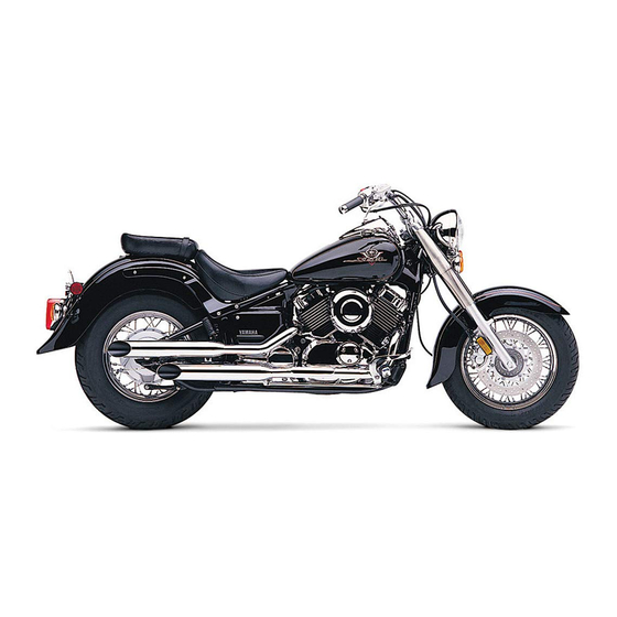
DESCRIPTION EAU10420 Right view 1. Engine oil filter element (page 7-12) 2. Battery (page 7-29) 3. Fuses (page 7-30) 4. Main switch/steering lock (page 4-1) 5. Air filter element (page 7-15) 6. Brake pedal (page 4-5) -
Page 17: Controls And Instruments
DESCRIPTION EAU10430 Controls and instruments 1. Clutch lever (page 4-4) 2. Left handlebar switches (page 4-3) 3. Speedometer unit (page 4-3) 4. Fuel tank cap (page 4-6) 5. Right handlebar switches (page 4-3) 6. Throttle grip (page 7-17) 7. Brake lever (page 4-5) -
Page 18: Instrument And Control Functions
INSTRUMENT AND CONTROL FUNCTIONS EAU10460 EAU10661 To lock the steering Main switch/steering lock All electrical systems are off. The key can be removed. EWA10061 WARNING Never turn the key to “OFF” or “LOCK” while the vehicle is moving. Otherwise the electrical systems will be switched off, which may result in loss of control or an accident. -
Page 19: Indicator And Warning Lights
This warning light comes on or flashes if a problem is detected in the electrical circuit monitoring the engine. If this oc- curs, have a Yamaha dealer check the 1. Push. self-diagnosis system. (See page 4-3 1. High beam indicator light “... -
Page 20: Speedometer Unit
If a problem is detected in any of those circuits, the engine trouble warning light will come on or flash. If this occurs, have a Yamaha dealer check the vehi- cle. ECA11170 NOTICE 1. Tripmeter reset knob To prevent engine damage, be sure 2. -
Page 21: Clutch Lever
INSTRUMENT AND CONTROL FUNCTIONS EAU12400 EAU12500 EAU12820 Dimmer switch “ ” Horn switch “ ” Clutch lever Set this switch to “ ” for the high Press this switch to sound the horn. beam and to “ ” for the low beam. EAU12660 Engine stop switch “... -
Page 22: Shift Pedal
INSTRUMENT AND CONTROL FUNCTIONS EAU12871 EAU12890 EAU12941 Shift pedal Brake lever Brake pedal 1. Shift pedal 1. Brake lever 1. Brake pedal 2. Neutral position The brake lever is located at the right The brake pedal is on the right side of The shift pedal is located on the left handlebar grip. -
Page 23: Fuel Tank Cap
INSTRUMENT AND CONTROL FUNCTIONS EAU13121 2. Turn the key counterclockwise to EAU13221 Fuel tank cap Fuel the original position, remove it, and Make sure there is sufficient gasoline in then close the lock cover. the tank. EWA10881 WARNING The fuel tank cap cannot be installed unless the key is in the lock. - Page 24 EWA15151 WARNING Your Yamaha engine has been de- Gasoline is poisonous and can signed to use regular unleaded gaso- cause injury or death. Handle gaso- line with a pump octane number line with care.
-
Page 25: Catalytic Converters
INSTRUMENT AND CONTROL FUNCTIONS EAU13445 ECA10701 EAU13550 Catalytic converters Fuel cock NOTICE This vehicle is equipped with catalytic The fuel cock supplies fuel from the Use only unleaded gasoline. The use converters in the exhaust system. tank to the carburetors while also filter- of leaded gasoline will cause unre- EWA10862 ing it. -
Page 26: Starter (Choke) Knob
INSTRUMENT AND CONTROL FUNCTIONS This indicates reserve. With the fuel EAU13620 Starter (choke) knob “ ” cock lever in this position, the fuel re- serve is made available. Turn the fuel cock lever to this position if you run out of fuel while riding. -
Page 27: Seats
INSTRUMENT AND CONTROL FUNCTIONS EAU14184 Tightening torque: Seats Passenger seat nut: 13 Nm (1.3 m·kgf, 9.4 ft·lbf) Passenger seat To remove the passenger seat Remove the nut and washer, and then pull the passenger seat up. 1. Bolt 2. Passenger seat holder To install the rider seat 1. -
Page 28: Helmet Holder
INSTRUMENT AND CONTROL FUNCTIONS 2. Install the passenger seat holder EAU14282 EAU14481 Helmet holder Storage compartment by installing its bolts. The storage compartment is located on 3. Install the passenger seat. the left side of the vehicle. Make sure that the seats are properly To open the storage compartment secured before riding. -
Page 29: Adjusting The Shock Absorber Assembly
INSTRUMENT AND CONTROL FUNCTIONS EAU14865 Use the special wrench and Adjusting the shock absorber extension bar included in the assembly owner’s tool kit to make the This shock absorber assembly is adjustment. equipped with a spring preload adjust- ing ring. ECA10101 NOTICE To avoid damaging the mechanism,... -
Page 30: Luggage Strap Holders
Take the shock Yamaha’s ignition circuit cut-off absorber assembly to a Yamaha system has been designed to assist dealer for any service. the operator in fulfilling the respon- sibility of raising the sidestand be- fore starting off. -
Page 31: Ignition Circuit Cut-Off System
INSTRUMENT AND CONTROL FUNCTIONS this system regularly and have a EAU15314 Ignition circuit cut-off system Yamaha dealer repair it if it does not The ignition circuit cut-off system (com- function properly. prising the sidestand switch, clutch switch and neutral switch) has the fol- lowing functions. - Page 32 INSTRUMENT AND CONTROL FUNCTIONS WARNING With the engine turned off: 1. Move the sidestand down. If a malfunction is noted, have a Yamaha 2. Make sure that the engine stop switch is set to “ ”. dealer check the system before riding.
-
Page 33: For Your Safety - Pre-Operation Checks
Final gear oil • Check vehicle for oil leakage. 7-14 • Check operation. • If soft or spongy, have Yamaha dealer bleed hydraulic system. • Check lever free play. • Adjust if necessary. Front brake • Check brake pads for wear. - Page 34 • Make sure that operation is smooth. • Check cable free play. Throttle grip 7-17, 7-25 • If necessary, have Yamaha dealer adjust cable free play and lubricate cable and grip housing. • Make sure that operation is smooth. Control cables 7-25 •...
-
Page 35: Operation And Important Riding Points
The time necessary light should come on. If not, ask a for starter (choke) use depends upon Yamaha dealer to check the elec- the ambient temperature. Tempera- trical circuit. tures above 10 °C (50 °F) require about 4. -
Page 36: Starting A Warm Engine
OPERATION AND IMPORTANT RIDING POINTS ECA11042 EAU16640 EAU16671 Starting a warm engine Shifting NOTICE Follow the same procedure as for start- For maximum engine life, never ac- ing a cold engine with the exception celerate hard when the engine is that the starter (choke) is not required cold! when the engine is warm. - Page 37 OPERATION AND IMPORTANT RIDING POINTS ECA10260 4. At the recommended shift points 3. Shift the transmission into the neu- NOTICE shown in the following table, close tral position when the motorcycle the throttle, and at the same time, is almost completely stopped. The Even with the transmission in the neutral position, do not quickly pull the clutch lever in.
-
Page 38: Engine Break-In
Yamaha dealer During this period, prolonged full-throt- Do not park on a slope or on soft check the vehicle. -
Page 39: Periodic Maintenance And Adjustment
– possibly leading to pending on the weather, terrain, geo- that is certified (if applicable). Yamaha death. See page 2-1 for more in- graphical location, and individual use, dealers are trained and equipped to... -
Page 40: Owner's Tool Kit
If you do not have the tools or experi- ence required for a particular job, have a Yamaha dealer perform it for you. -
Page 41: Periodic Maintenance Chart For The Emission Control System
From 24000 mi (37000 km) or 36 months, repeat the maintenance intervals starting from 8000 mi (13000 km) or 12 months. Items marked with an asterisk require special tools, data and technical skills, have a Yamaha dealer perform the service. EAU17601... - Page 42 PERIODIC MAINTENANCE AND ADJUSTMENT INITIAL ODOMETER READINGS 600 mi 4000 mi 8000 mi 12000 mi 16000 mi 20000 mi ITEM ROUTINE (1000 km) (7000 km) (13000 km) (19000 km) (25000 km) (31000 km) 1 month 6 months 12 months 18 months 24 months 30 months •...
-
Page 43: General Maintenance And Lubrication Chart
PERIODIC MAINTENANCE AND ADJUSTMENT EAU32186 General maintenance and lubrication chart INITIAL ODOMETER READINGS 600 mi 4000 mi 8000 mi 12000 mi 16000 mi 20000 mi ITEM ROUTINE (1000 km) (7000 km) (13000 km) (19000 km) (25000 km) (31000 km) 1 month 6 months 12 months 18 months... - Page 44 PERIODIC MAINTENANCE AND ADJUSTMENT INITIAL ODOMETER READINGS 600 mi 4000 mi 8000 mi 12000 mi 16000 mi 20000 mi ITEM ROUTINE (1000 km) (7000 km) (13000 km) (19000 km) (25000 km) (31000 km) 1 month 6 months 12 months 18 months 24 months 30 months •...
- Page 45 √ √ √ √ √ √ 23 * • Check operation. switches Control and meter • Apply Yamaha chain and cable √ √ √ √ √ √ 24 * cables lube or engine oil thoroughly. • Check operation and free play.
- Page 46 PERIODIC MAINTENANCE AND ADJUSTMENT EAU17620 The air filter needs more frequent service if you are riding in unusually wet or dusty areas. Hydraulic brake system • When disassembling the master cylinder or caliper cylinder, always replace the brake fluid. Check the brake fluid level regularly and fill as required.
-
Page 47: Removing And Installing Panels
PERIODIC MAINTENANCE AND ADJUSTMENT EAU18771 To install the panel Removing and installing pan- Place the panel in the original position, and then install the bolts. The panels shown need to be removed to perform some of the maintenance EAU19151 Panel B jobs described in this chapter. -
Page 48: Checking The Spark Plugs
Do not attempt to 1. Spark plug cap diagnose such problems yourself. In- 2. Remove the spark plug as shown, stead, have a Yamaha dealer check with the spark plug wrench includ- the vehicle. ed in the owner’s tool kit. -
Page 49: Canister (For California Only)
PERIODIC MAINTENANCE AND ADJUSTMENT 3. Check each spark plug for elec- To install a spark plug EAU19672 Canister (for California only) trode erosion and excessive car- 1. Clean the surface of the spark plug bon or other deposits, and replace gasket and its mating surface, and it if necessary. -
Page 50: Engine Oil And Oil Filter Element
PERIODIC MAINTENANCE AND ADJUSTMENT EAU19745 3. Remove the engine oil filler cap, Engine oil and oil filter ele- the engine oil drain bolt and its ment gasket to drain the oil from the The engine oil level should be checked crankcase. - Page 51 PERIODIC MAINTENANCE AND ADJUSTMENT Tightening torque: Engine oil drain bolt: 43 Nm (4.3 m·kgf, 31 ft·lbf) 9. Refill with the specified amount of the recommended oil, and then in- stall and tighten the oil filler cap. Recommended engine oil: See page 9-1. 1.
-
Page 52: Final Gear Oil
If any higher. leakage is found, have a Yamaha deal- Make sure that no foreign mate- The oil level should be at the brim of the er check and repair the vehicle. In addi- rial enters the crankcase. -
Page 53: Cleaning The Air Filter Element
PERIODIC MAINTENANCE AND ADJUSTMENT EAU33383 Tightening torque: Tightening torque: Cleaning the air filter element Final gear oil filler bolt: Final gear oil drain bolt: The air filter element should be cleaned 23 Nm (2.3 m·kgf, 17 ft·lbf) 23 Nm (2.3 m·kgf, 17 ft·lbf) at the intervals specified in the periodic maintenance and lubrication chart. - Page 54 PERIODIC MAINTENANCE AND ADJUSTMENT If dust or water collects in the air filter check hose, remove the clamp from it, and then remove the plug to drain the hose. 1. Air filter element 1. Air filter element holder 2. Projection 4.
-
Page 55: Carburetors
Check the engine idling speed and, if tem, which require very sophisticated necessary, have it corrected by a adjustment. Therefore, all carburetor Yamaha dealer. adjustments should be left to a Yamaha dealer, who has the necessary profes- Engine idling speed: 1150–1250 r/min sional knowledge and experience. -
Page 56: Valve Clearance
Rear: from occurring, the valve clearance the specified tires. 225 kPa (2.25 kgf/cm², 33 psi) must be adjusted by a Yamaha dealer XVS65A 90–180 kg (198–397 lb) at the intervals specified in the periodic Tire air pressure XVS65AC 90–178 kg (198–392 lb): maintenance and lubrication chart. - Page 57 After extensive tests, only the tires list- and brake-related parts, includ- ed below have been approved for this ing the tires, should be left to a model by Yamaha Motor Co., Ltd. Yamaha dealer, who has the 1. Tire sidewall necessary professional knowl- 2.
-
Page 58: Spoke Wheels
4. Rubber cover age before each ride. If any dam- age is found, have a Yamaha The clutch lever free play should mea- dealer replace the wheel. Do not sure 10.0–15.0 mm (0.39–0.59 in) as attempt even the smallest repair to shown. -
Page 59: Adjusting The Brake Lever Free Play
PERIODIC MAINTENANCE AND ADJUSTMENT 6. To increase the clutch lever free EAU22093 Adjusting the brake lever free play, turn the adjusting nut in direc- play tion (a). To decrease the clutch le- ver free play, turn the adjusting nut in direction (b). 7. -
Page 60: Adjusting The Brake Pedal Position And Free Play
1. Distance between brake pedal and footrest 2. Brake pedal free play EWA10670 WARNING It is advisable to have a Yamaha dealer make these adjustments. The brake pedal position should be ad- 1. Locknut justed before adjusting the brake pedal 2. -
Page 61: Brake Light Switches
1. Brake pad wear indicator groove by a Yamaha dealer. Each front brake pad is provided with Turn the rear brake light switch adjust- wear indicator grooves, which allow... -
Page 62: Checking The Brake Fluid Level
When checking the fluid level, brake fluid level goes down sud- the wear limit line, have a Yamaha make sure that the top of the mas- denly, have a Yamaha dealer dealer replace the brake shoes as a ter cylinder is level by turning the check the cause. -
Page 63: Changing The Brake Fluid
EAU23093 EAU49920 Changing the brake fluid Checking and lubricating the Checking and lubricating the Have a Yamaha dealer change the cables throttle grip and cable brake fluid at the intervals specified in The operation of all control cables and The operation of the throttle grip should... -
Page 64: Checking And Lubricating The Brake And Shift Pedals
PERIODIC MAINTENANCE AND ADJUSTMENT EAU44272 EAU23142 Recommended lubricants: Checking and lubricating the Checking and lubricating the Brake lever: brake and shift pedals brake and clutch levers Silicone grease Clutch lever: Brake lever Lithium-soap-based grease The operation of the brake and shift pedals should be checked before each Clutch lever ride, and the pedal pivots should be lu-... -
Page 65: Checking And Lubricating The Sidestand
The swingarm pivots must be lubricat- intervals specified in the periodic main- ed by a Yamaha dealer at the intervals tenance and lubrication chart. specified in the periodic maintenance and lubrication chart. -
Page 66: Checking The Steering
Yamaha dealer check or re- [EWA10751] tion chart. If there is play in the wheel 2. Hold the lower ends of the front pair it. -
Page 67: Battery
To charge the battery burns. Avoid any contact with Have a Yamaha dealer charge the bat- skin, eyes or clothing and al- tery as soon as possible if it seems to ways shield your eyes when have discharged. -
Page 68: Replacing The Fuses
PERIODIC MAINTENANCE AND ADJUSTMENT nect the negative lead before EAU23526 avoid causing extensive dam- Replacing the fuses disconnecting the positive lead. age to the electrical system and possibly a fire. [ECA16302] [EWA15131] 2. If the battery will be stored for more than two months, check it at least once a month and fully charge it if necessary. -
Page 69: Replacing The Headlight Bulb
Thor- 4. If the fuse immediately blows oughly clean off any dirt and fin- again, have a Yamaha dealer gerprints on the headlight bulb check the electrical system. using a cloth moistened with al- cohol or thinner. -
Page 70: Replacing A Turn Signal Light Bulb Or The Tail/Brake Light Bulb
6. Install the headlight unit by install- 1. Remove the lens by removing the ing the screws. screws. 7. Have a Yamaha dealer adjust the headlight beam if necessary. 1. Headlight coupler 2. Headlight bulb cover 3. Unhook the headlight bulb holder, and then remove the burnt-out bulb. -
Page 71: Supporting The Motorcycle
PERIODIC MAINTENANCE AND ADJUSTMENT 2. Remove the burnt-out bulb by EAU24350 a jack either under each side of the Supporting the motorcycle pushing it in and turning it counter- frame in front of the rear wheel or under Since this model is not equipped with a clockwise. -
Page 72: Front Wheel
PERIODIC MAINTENANCE AND ADJUSTMENT EAU24360 2. Lift the wheel up between the fork Front wheel legs. EAU24601 To remove the front wheel Make sure that there is enough space EWA10821 between the brake pads before insert- WARNING ing the brake disc and that the slot in To avoid injury, securely support the the speedometer gear unit fits over the vehicle so there is no danger of it... -
Page 73: Rear Wheel
PERIODIC MAINTENANCE AND ADJUSTMENT EAU25080 4. Remove the brake pedal free play Tightening torque: Rear wheel adjusting nut, and then disconnect Wheel axle: the brake rod from the brake cam- 59 Nm (5.9 m·kgf, 43 ft·lbf) EAU25142 shaft lever. To remove the rear wheel 6. - Page 74 PERIODIC MAINTENANCE AND ADJUSTMENT 1. Bolt 1. Drive shaft 1. Middle gear universal joint 2. Final gear case 2. Drive shaft 7. Lift the rear wheel off the ground 2. Install the final gear case bolts. Make sure to support the drive shaft as according to the procedure on 3.
-
Page 75: Troubleshooting
After adjusting the brake pedal free self. However, should your motorcycle play, check the operation of the require any repair, take it to a Yamaha brake light. dealer, whose skilled technicians have the necessary tools, experience, and know-how to service the motorcycle properly. -
Page 76: Troubleshooting Chart
Remove the spark plugs and check the electrodes. The engine does not start. Have a Yamaha dealer check the vehicle. Check the battery. 4. Battery The engine turns over The battery is good. -
Page 77: Motorcycle Care And Storage
Be ble. Rust and corrosion can develop ECA10772 even if high-quality components are sure to consult a Yamaha dealer for NOTICE used. A rusty exhaust pipe may go un- advice on what products to use be- Avoid using strong acidic wheel fore cleaning the vehicle. - Page 78 MOTORCYCLE CARE AND STORAGE off any detergent residue using Test the product on a small hid- plenty of water, as it is harmful den part of the windshield to Salt sprayed on roads in the winter may to plastic parts. make sure that it does not leave remain well into spring.
-
Page 79: Storage
WARNING ing it with a tarp, while it is still Contaminants on the brakes or tires Consult a Yamaha dealer for ad- wet, will allow water and humid- can cause loss of control. vice on what products to use. - Page 80 MOTORCYCLE CARE AND STORAGE 2. For motorcycles equipped with a WARNING! To prevent dam- cessively cold or warm place [less fuel cock that has an “OFF” posi- age or injury from sparking, than 0 °C (30 °F) or more than 30 tion: Turn the fuel cock lever to make sure to ground the °C (90 °F)].
-
Page 81: Specifications
Spark plug gap: –20 –10 0 10 20 30 40 50 ˚C With oil and fuel: 0.8–0.9 mm (0.031–0.035 in) XVS65A 233 kg (514 lb) Clutch: Recommended engine oil grade: XVS65AC 235 kg (518 lb) Clutch type: API service SG type or higher, JASO... - Page 82 Type: 38/14 (2.714) Loading: Single disc brake 2nd: Maximum load: Operation: 38/20 (1.900) XVS65A 180 kg (397 lb) Right hand operation 3rd: XVS65AC 178 kg (392 lb) Recommended fluid: 35/24 (1.458) (Total weight of rider, passenger, cargo and DOT 4...
- Page 83 SPECIFICATIONS Voltage, capacity: Carburetor heater fuse: 12 V, 10.0 Ah 15.0 A Headlight: Ignitor unit fuse: 5.0 A Bulb type: Halogen bulb Bulb voltage, wattage × quantity: Headlight: 12 V, 60 W/55 W × 1 Tail/brake light: 12 V, 8.0 W/27.0 W × 1 Front turn signal/position light: 12 V, 23 W/8.0 W ×...
-
Page 84: Consumer Information
Record the key identification number, vehicle identification number and mod- el label information in the spaces pro- vided below for assistance when ordering spare parts from a Yamaha dealer or for reference in case the vehi- cle is stolen. KEY IDENTIFICATION NUMBER: 1. - Page 85 This information illustration. This label shows specifica- will be needed when ordering spare tions related to exhaust emissions as parts from a Yamaha dealer. required by federal law, state law and Environment Canada. 10-2...
-
Page 86: Reporting Safety Defects
If you believe that your vehicle has a defect which could cause a crash or could cause injury or death, you should immediately inform the National Highway Traffic Safety Administration (NHTSA) in addition to notifying Yamaha Motor Corporation, U.S.A. If NHTSA receives similar complaints, it may open an investigation, and if it finds that a safety defect exists in a group of vehicles, it may order a recall and remedy campaign. -
Page 87: Motorcycle Noise Regulation
CONSUMER INFORMATION EAU26560 Motorcycle noise regulation TAMPERING WITH NOISE CONTROL SYSTEM PROHIBITED: Federal law prohibits the following acts or the causing thereof: (1) The removal or rendering inoperative by any person other than for purposes of maintenance, repair, or replacement of any device or element of design incorporated into any new ve- hicle for the purpose of noise control prior to its sale or delivery to the ultimate purchaser or while it is in use or (2) the use of the vehicle after such device or element of design has been removed or rendered inoperative by any person. -
Page 88: Maintenance Record
CONSUMER INFORMATION EAU26632 Maintenance record Copies of work orders and/or receipts for parts purchased and installed on your vehicle will be required to document that maintenance has been completed in accordance with the emissions warranty. The chart below is printed only as a reminder that maintenance work is required. - Page 89 CONSUMER INFORMATION Maintenance Date of Servicing dealer Mileage Remarks interval service name and address 36000 mi (55000 km) or 54 months 40000 mi (61000 km) or 60 months 10-6...
-
Page 90: Warranty
CONSUMER INFORMATION EAU26663 YAMAHA MOTOR CORPORATION, U.S.A. STREET AND ENDURO MOTORCYCLE LIMITED WARRANTY Yamaha Motor Corporation, U.S.A. hereby warrants that CUSTOMER’S RESPONSIBILITY under this Engine new Yamaha motorcycles will be free from defects in warranty shall be to: Displacement Period... - Page 91 CUSTOMER SERVICE What costs are my responsibility during the warranty period? If your machine requires warranty service, you must take it to any authorized Yamaha The customer’s responsibility includes all costs of normal maintenance services, motorcycle dealer within the continental United States. Be sure to bring your warranty non-warranty repairs, accident and collision damages, and oil, oil filters, air filters, registration card or other valid proof of the original date of purchase.
- Page 92 This excellent Y.E.S. plan coverage is only available to dealer to see how comforting uninterrupted factory- Yamaha owners like you, and only while your Yamaha is still backed protection can be. within the Yamaha Limited Warranty period. So visit your authorized Yamaha dealer to get all the facts.
- Page 93 Yamaha Limited Warranty expires. A special note: If visiting your dealer isn’t convenient, contact Yamaha with your Primary ID number (your frame number). We’ll be happy to help you get the Y.E.S. coverage you need.
- Page 94 INDEX Parking ............6-4 Part locations .......... 3-1 Air filter element, cleaning..... 7-15 Final gear oil ......... 7-14 Front fork, checking ......7-27 Fuel............4-6 Safety defects, reporting .......10-3 Battery........... 7-29 Fuel cock ..........4-8 Safety information ........2-1 Brake and clutch levers, checking and Fuel tank cap ..........
- Page 95 INDEX Turn signal switch........4-4 Valve clearance ........7-18 Vehicle Emission Control Information label............ 10-2 Vehicle identification number....10-1 Warranty, extended ......10-9 Warranty, limited........10-7 Wheel bearings, checking ....7-28 Wheel (front) ......... 7-34 Wheel (rear).......... 7-35 Wheels..........7-20...
- Page 98 YAMAHA MOTOR CO., LTD. PRINTED ON RECYCLED PAPER PRINTED IN JAPAN 2010.04-0.3×1 CR...
Need help?
Do you have a question about the XVS65A and is the answer not in the manual?
Questions and answers