Table of Contents
Advertisement
Advertisement
Table of Contents

Related Manuals for Ametek Sorensen Asterion AST Series


Summary of Contents for Ametek Sorensen Asterion AST Series
- Page 1 DC Asterion 1U Operation Manual M330460-01 Rev A www.powerandtest.com...
- Page 3 AMETEK Electronic Instruments Group (a division of AMETEK, Inc.), is a global leader in the design and manufacture of precision, programmable power supplies for R&D, test and measurement, process control, power bus simulation and power conditioning applications across diverse industrial segments. Offering bench-top supplies to rack-...
- Page 4 AMETEK will, at its expense, deliver the repaired or replaced Product or parts to the Buyer. Any warranty of AMETEK will not apply if the Buyer is in default under the Purchase Order Agreement or where the Product or any part thereof: •...
- Page 5 Use safety glasses during open cover checks to avoid personal injury by any sudden component failure. Neither AMETEK Programmable Power Inc., San Diego, California, USA, or any of the subsidiary sales organizations, can accept any responsibility for personnel, material or inconsequential injury, loss or damage that results from improper use of the equipment and accessories.
- Page 6 SAFETY SYMBOLS WARNING: Electrical Shock Hazard HAZARD: Strong oxidizer GENERAL WARNING/CAUTION: Read the accompanying message for specific information. BURN HAZARD: Hot Surface Warning. Allow to cool before servicing. DO NOT TOUCH: Touching some parts of the instrument without protection or proper tools could result in damage to the part(s) and/or the instrument. TECHNICIAN SYMBOL: All operations marked with this symbol are to be performed by qualified maintenance personnel only.
- Page 7 FCC NOTICE This equipment has been tested and found to comply with the limits for a Class A digital device, pursuant to part 15 of the FCC Rules. These limits are designed to provide reasonable protection against harmful interference when the equipment is operated in a commercial environment. This equipment generates, uses, and can radiate radio frequency energy and, if not installed and used in accordance with the instruction manual, may cause harmful interference to radio communications.
- Page 8 About DC Asterion Series ABOUT THIS MANUAL AND REGULATORY COMPLIANCE This manual has been written for the Asterion DC Series of power supplies, which have been designed and certified to meet the Low Voltage and Electromagnetic Compatibility Directive Requirements of the European Community. These models have been designed and tested to meet the Electromagnetic Compatibility directive (European Council directive 2014/30/EU;...
-
Page 9: Table Of Contents
DC Asterion Series Contents CONTENTS OVERVIEW ............1-1 General Description ..................1-1 Specifications ....................1-3 1.2.1 Output Current and Voltage Models ............... 1-3 1.2.2 AC input specifications ................... 1-3 1.2.3 Output Power derating characteristics with AC input Voltage ......1-4 1.2.4 DC output programming and measurement specifications ...... - Page 10 Contents DC Asterion Series 2.12 Load Considerations .................. 2-17 2.12.1 Inductive and Stored-Energy Loads .............2-17 2.13 Rear Panel User Interface Connectors ............. 2-17 2.13.1 Remote Analog programming and External user control interface ....2-18 2.13.2 RS-232C Serial Interface ................2-23 2.13.3 USB interface ....................2-24 2.13.4 LAN interface ....................2-25 OPERATION ............
- Page 11 DC Asterion Series Contents 3.6.2 Remote Power Programming by Voltage Source .........3-49 3.6.3 Remote Power Programming by 4-20mA Source ........3-49 Remote Overvoltage Programming ............3-50 Remote Output On/Off Control ..............3-50 3.8.1 Remote Output ON/OFF by Contact Closure ..........3-51 3.8.2 Remote Output ON/OFF Control by External Source ........3-51 Parallel and Series Operation ..............
- Page 12 Contents DC Asterion Series LIST OF TABLES Table 2-1. Rear Panel Connectors ................2-9 Table 2-2. AC Input Connector Pinout and Safety-Ground ......... 2-10 Table 2-3. AC Input Connector Type ................2-11 Table 2-4. DC Output Power Connections ..............2-12 Table 2-5.
- Page 13 DC Asterion Series Contents LIST OF FIGURES Figure 1-1. Asterion DC Series Power Supply, 1U Models .......... 1-1 Figure 1-2. Asterion DC Series Model Number Decoding ........... 1-2 Figure 2-1. Rack mounting, 1U Models ................ 2-4 Figure 2-2. Installation Drawing, Enhanced (front panel version) 1U Models ....2-6 Figure 2-3.
- Page 14 Contents DC Asterion Series Figure 3-26. Current Ramp-Screen (SW Trigger) ............3-13 Figure 3-27. Current Ramp-Screen (HW Trigger) ............. 3-13 Figure 3-28. Current Ramp-Screen (Abort) ..............3-13 Figure 3-29. Configuration Screen Top-Level Menu ..........3-15 Figure 3-30. Multi-Chassis Screen (Single Chassis) ..........3-15 Figure 3-31.
- Page 15 DC Asterion Series Contents Figure 3-68. LAN Screen (Restore Default) ............... 3-27 Figure 3-69. LAN Screen (Apply) ................3-27 Figure 3-70. Analog Screen ..................3-28 Figure 3-71. Analog Mode Settings 1 ................ 3-28 Figure 3-72. Analog Mode Settings Screen 2 ............3-28 Figure 3-73.
- Page 16 Contents DC Asterion Series Figure 3-109. Remote Output On/Off Using Isolated AC or DC Source..... 3-51 Figure 3-110. Remote Output On/Off Using Isolated TTL/CMOS Source ....3-51 Figure 3-111. Parallel Connection and Remote Sense ..........3-53 Figure 3-112. Series Connection with Anti-Parallel Diodes ........3-54 M330460-01 Rev A...
-
Page 17: Overview
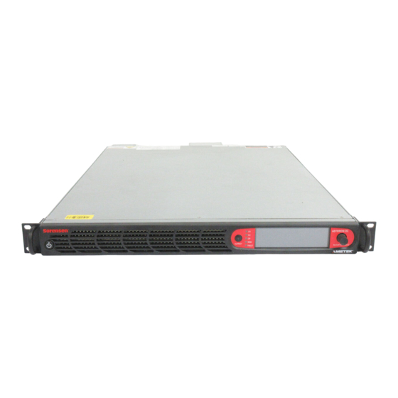
OVERVIEW General Description The Sorensen Asterion line of DC power supplies by AMETEK Programmable Power combines intelligence and flexibility to create an advanced platform of DC solutions. This easy-to-configure design features sophisticated technology for delivering high performance, programmable DC power. Its sleek design packs maximum power density into a low-profile form factor;... -
Page 18: Figure 1-2. Asterion Dc Series Model Number Decoding
Overview DC Asterion Series • DC power simulation • Commercial manufacturing and process control • Research and development • Automotive component and battery testing • ATE applications See Figure 1-2 for decoding the DC Asterion Series Model Number. AST XXX (AR) - XXX D X C - E X X SERIES Asterion UNIT OUTPUT VOLTAGE (VDC) -
Page 19: Specifications
DC Asterion Series Overview Specifications The following sections provide electrical, environmental, and physical specifications for the DC Asterion Series power supplies. Unless otherwise noted, the specifications are valid under the following conditions: a. Ambient temperature of 25 5C, after a 30-minute warm-up, and at fixed AC input line and load. -
Page 20: Output Power Derating Characteristics With Ac Input Voltage
Overview DC Asterion Series 1-PH Input Connections 2 wires + ground, 264 VAC, Maximum Line-Neutral 3-PH Input Connections 3 wires + ground; delta configuration; 264 VAC, maximum line-to-line 1500VAC primary to earth, 3000VAC on primary to SELV and Hazardous Isolation Voltage secondary to SELV isolation barriers ≤1% THDV... -
Page 21: Output Transient Specifications
DC Asterion Series Overview Maximum load regulation +/- 0.02% of rated voltage Temperature Drift +/- 100 PPM / degree Celsius Stability +/- 0.05% of rated voltage Constant Current Mode Maximum line regulation +/- 0.05% of rated current Maximum load regulation +/- 0.15% of rated current Temperature Drift +/- 100 PPM / degree Celsius... - Page 22 Overview DC Asterion Series 1.2.7 Remote Analog programming External user control interface characteristics Function Characteristics Independent Signal inputs for output voltage, current and power programming using External Analog Reference. Analog reference source is user selectable and can be a voltage, resistance or 4-20 mA source.
-
Page 23: Output Isolation
DC Asterion Series Overview Internal to power supply, signal output is from driver with input connected to open-collector of opto-isolator transistor Voltage Rating: Maximum 30 V, Minimum 4.5V for Active High, Current Maximum 0.5 A Output Signal, High state indicates fault state of the power supply. There is an Option to feed User Power to the FAULT signal. -
Page 24: Protection Function Characteristics
Overview DC Asterion Series Serial interface compliant to RS-232C; Protocol: data bits, 7 with parity and 8 without parity; stop bits, 2; baud rate, 9600 to 115200; RS-232C handshake, CTS and RTS; Connector: Subminiature-D, 9-contact receptacle. Parallel interface complies with IEEE-488.1, IEEE-488.2, and the SCPI command specification;... -
Page 25: Mechanical Specifications
DC Asterion Series Overview Vibration MIL-PRF-28800F, Class 3; 5-500 Hz per Paragraph 4.5.5.3.1 MIL-PRF-28800F, Class 3; 30G half-sine with 11ms duration per Shock Paragraph 4.5.5.4.1 Transportation Integrity ISTA Test Procedure 1A 1.2.12 Mechanical Specifications Parameter Specification H, 1.75” (44.45 mm); W (front panel), 19.0” (483mm); D, 24.0” (609.6mm); Dimensions H, 1.75”... -
Page 27: Installation
Minimum items included in the ship kit (P/N 5330339-01R): 1. AMETEK CD-ROM ( P/N M550008-01) containing the Asterion DC Series User Manual (P/N M330460-01), and the Asterion DC Series Programming Manual (P/N M330461-01). -
Page 28: Mechanical Installation
M4 nuts P/N MN-M04K-07, quantity two). 8. Rackmount flange bracket kit (P/N 5330241-01R, quantity two; includes four M4 mounting screws P/N FM1001). Note: If any of these parts are missing, contact AMETEK Customer Service Department at 858-458-0223 (local) or 1-800-733-5427 (toll free). Optional accessories: 1. -
Page 29: Rack Mounting
Recommended rackmount kits are as follows: 1. Rackmount Slide Kit (Option): AMETEK part number 5330201-01R. 2. Rackmount Flange Bracket Kit (Option): AMETEK part number 5330241-01R. Install the rackmount kit as follows: 1. Install the slide sections, 1 , on both sides of the power supply chassis with screws, 6 , (three on each side). -
Page 30: Chassis Removal From Rack
Overview DC Asterion Series 5. Insert adjustable side sections, 2 , into stationary slide sections, 3 . Insert power supply chassis with installed slide sections, , into the adjustable slide sections, 2 . Figure 2-1. Rack mounting, 1U Models Chassis Removal from Rack The slides have a front disconnect feature and lock at full extension. -
Page 31: Outline Drawings
DC Asterion Series Overview Outline drawings Figure 2-2 shows the outlines and overall dimensions for installation of the 1U front panel version (Enhanced) of the Asterion DC Series power source. Figure 2-3 shows the rear panel view of the power source and locations of the rear panel connectors. -
Page 32: Figure 2-2. Installation Drawing, Enhanced (Front Panel Version) 1U Models
Overview DC Asterion Series Figure 2-2. Installation Drawing, Enhanced (front panel version) 1U Models M330460-01 Rev A... -
Page 33: Rear Panel Input/ Output Connections
DC Asterion Series Overview Figure 2-3. Rear Panel View, 1U Models, (with GPIB option) Figure 2-4. Rear Panel Protective Cover Installation Rear Panel Input/ Output Connections Figure 2-3 for the rear panel view of the 1U model power source showing the location of the connectors. - Page 34 Overview DC Asterion Series WARNING! High voltage present at rear panel poses risk of electrical shock. The input and output covers maintain protection against hazardous voltages. Do not remove protective covers on AC input or DC output. Refer installation and servicing to qualified personnel.
-
Page 35: Ac Input Power Connection
DC Asterion Series Overview RS-232C connector for remote digital control; External digital RS-232C connector see section 2.13.2. interface USB type B connector for remote digital control; External digital USB Connector see section 2.13.3. interface Ethernet connector for remote digital control; see External digital Ethernet connector section 2.13.4. -
Page 36: Table 2-2. Ac Input Connector Pinout And Safety-Ground
Overview DC Asterion Series Figure 2-5. AC Input Connector and Safety-Ground Stud A 1-Phase input is connected to terminals L1/L2 or L2/L3 (do not connect a 1-Phase input between L1/L3), while a 3-Phase input is connected to L1/L2/L3 (a connection to neutral is not utilized with 3-Phase input). -
Page 37: 1-Phase Ac Input Operation
DC Asterion Series Overview Use the GND pin (G) provided in the input AC connector or the Stud provided in the Safety-Ground rear panel for Safety-Ground Connection. For using the rear panel M4-0.7 x 7 stud, use nut tightening torque is 1.1 Nm (10 lb-in) max. Table 2-3. -
Page 38: Dc Output Power Connection
Overview DC Asterion Series DC output power connection Figure 2-6. DC Output Busbar Output Power of the DC-Asterion series is through bus bars (POS and NEG) and the size could vary depending on the voltage and power models. For example, see Figure 2-6 for 40V-60V models. -
Page 39: Table 2-6. Analog Programming And External User Control Interface Connector Type
Overview Figure 2-7. Remote sense connector Connector Type 3 Pin Mating type header on the chassis Mating connector Ametek P/N, 856-390-03 Mating Manufacturer P/N: Molex 39-01-4031 Remote Sense Connector Crimp Pin Ametek P/N, 856-390-00 Mating Manufacturer P/N: Molex 39-00-0182 Table 2-6. Analog Programming and External User Control Interface Connector Type Output voltage sensing is user-selectable to be either local sense or remote sense. -
Page 40: Wire Gauge Selection
Overview DC Asterion Series 1. If the remote sense is selected and the remote sense wiring is not done to the power supply unit. 2. If the remote sense is connected in the reverse polarity. 3. If the load cable drop exceeds 5% of the rated output voltage. On the remote sense fault condition, the output voltage would get programmed to zero. -
Page 41: Table 2-7. Minimum Wire Size
DC Asterion Series Overview recommendations are for 30°C ambient, and for copper wire only. This table is derived from the National Electrical Code and is for reference only. Local laws and conditions may have different requirements. For higher ratings, wires can be paralleled; refer to the National Electrical Code for guidelines. -
Page 42: Table 2-8. Wire Resistance And Voltage Drop, 20°C
Overview DC Asterion Series Be careful when using published commercial utility wiring codes. These codes are designed for the internal wiring of homes and buildings and accommodate the safety factors of wiring loss, heat, breakdown insulation, aging, etc. However, these codes consider that up to 5% voltage drop is acceptable. -
Page 43: Load Considerations
DC Asterion Series Overview Load Considerations 2.12 This section provides guidelines for incorporating protective diode networks at the output of the power supply to prevent damage while driving inductive loads or loads having stored energy that could be circulated back to the power supply. 2.12.1 Inductive and Stored-Energy Loads To prevent damage to the power supply from inductive voltage kickback, connect an antiparallel... -
Page 44: Remote Analog Programming And External User Control Interface
Connector Connector Type High-density, 44-socket, receptacle (female) Subminiature-D. Remote Analog programming and external Mating connector Ametek P/N, 856-044-01 user control interface Mating Manufacturer P/N: NORCOMP 180-044- 102L001 or equivalent Table 2-9. Analog Programming and External User Control Interface Connector Type... - Page 45 DC Asterion Series Overview Signal input for setting Overvoltage using External Analog Reference Voltage. Remote Analog Range: 0.25 V to user selectable maximum range (2 V to 10 V) for 5% to 110% of the full- Programming of scale Output Voltage. Overvoltage Programming accuracy and linearity: ±1% of full-scale output Monitor Signals for the Output Voltage, Current and Power.
- Page 46 (pins 12, 18, 22, 28, 29, 36, 40, and 41). Refer to Table 2-11 for pin details. 44 Pin Conn Ametek P/N: 856-044-00 Reference Type Functional Description Isolated remote control input for output on/off with an applied AC/DC voltage source.
- Page 47 DC Asterion Series Overview Remote control input overvoltage programming using a voltage source: 0-10 5 OVPPRG_VSOUR ANALOG IN VDC = 0-110% of full-scale output voltage. Do not exceed an input of 12 VDC. Signal return is Pin 18. Monitor signal for output voltage: 0-10 VDC = 0-100% of full-scale output voltage.
- Page 48 Overview DC Asterion Series 22 MON_RTN* ANALOG GND Return for Pin 6, 21, 35. User digital output, cause to be assigned by user. Output high state either min 4.5V or 24 TRIG_OUT DIGITAL OUT voltage on Pin 30 (USER_PWR) minus 1V, whichever is higher.
-
Page 49: Rs-232C Serial Interface
The power source functions as Data Circuit-terminating Equipment (DCE). The cable connecting to the Data Terminal Equipment (DTE) should be straight-through (one-to- one contact connections). For EMC considerations a ferrite core can be added to the cable Ametek P/N: 991-642-28, Manufacturer P/N: CS28B0642. Figure 2-11. RS-232C Interface Connector Connector... -
Page 50: Usb Interface
Table 2-15 for pin descriptions. A standard USB cable between the Asterion Series power source and a computer should be used. For EMC considerations a ferrite core can be added to the cable Ametek P/N: 991-642-28, Manufacturer P/N: CS28B0642. -
Page 51: 2.13.4 Lan Interface
LAN interface, refer to the DC-Asterion Series Programming Manual P/N M330461-01 distributed on the CD, M550008-01. For EMC considerations a ferrite core can be added to the cable Ametek P/N: 991-642-28, Manufacturer P/N: CS28B0642. -
Page 52: Table 2-17. Lan Interface 8P8C Modular Connector Pinout
Overview DC Asterion Series EIA/TIA 568B Ethernet Signal EIA/TIA 568A Crossover Transmit/Receive Data 3 - Brown with white stripe or Brown with white stripe or solid brown solid brown Table 2-17. LAN Interface 8P8C Modular Connector Pinout 2-26 M330460-01 Rev A... - Page 53 DC Asterion Series Overview This page intentionally left blank. M330460-01 Rev A 2-27...
-
Page 55: Operation
OPERATION Front Panel Display Menu and Functionality 3.1.1 Power-Up Screens At initial power-on, the display shows the AST-DC Splash screen, Refer to Figure 3-1, followed by the Start-Up screen with the manufacturer, model number, serial number, firmware revisions and last calibration date, Refer to Figure 3-2, and finally the Dashboard screen, Refer to Figure 3-7. -
Page 56: Home Screen Top-Level Menu
Overview DC Asterion Series Figure 3-3. Output-Enabled Warning Screen 3.1.2 Home Screen Top-Level Menu Selecting the Home icon or Up arrow will open the HOME screen. Each menu of a screen could be selected by tapping its associated selection-field box through the touch-screen, or by selecting it with the rotary encoder and depressing (clicking) the rotary encoder SELECT switch. -
Page 57: Table 3-1. Home Screen Menu Content
DC Asterion Series Overview There are four virtual buttons visible on a screen: UP, LEFT, and RIGHT arrows, and HOME icon. Those buttons that are highlighted are active for the screen being displayed. The arrow buttons will scroll to the next page of the menu structure in the direction indicated. -
Page 58: Dashboard Screen Top-Level Menu
Overview DC Asterion Series 3.1.3 Dashboard Screen Top-Level Menu The DASHBOARD screen top-level menu is used to change output parameters and simultaneously view output measurements. The most commonly used output parameters are in the DASHBOARD screen menu. The DASHBOARD screen is the default menu that is displayed after power-on, refer to Figure 3-7. -
Page 59: Figure 3-8. Real-Time, Immediate Output Parameter Adjustment
DC Asterion Series Overview requires clicking on a parameter selection-field box with the encoder switch to select the parameter and display its selection-field highlighted and with a value entry window (refer to Figure 3-8). The rotary encoder could then be used to continuously adjust the parameter value, up and down, as it is rotated. -
Page 60: Output Program Screen
Overview DC Asterion Series Figure 3-10. Default Screen With the understanding of the dashboard screen features, user can perform basic functionality and verify the output voltage and output current in various modes of operation as described in Section 3.1.3 (Dashboard Screen). 3.1.4 Output Program Screen The OUTPUT PROGRAM screen provides setting of output related items such as... -
Page 61: Figure 3-12. Voltage Setting
DC Asterion Series Overview Entry Description ETTINGS VOLTAGE Programs the output voltage in Volts. Negative values can also be entered, refer to Figure 3-12. Figure 3-12. Voltage Setting CURRENT Programs the output current in Amperes. The default is full-scale for the model, refer to Figure 3-13. Figure 3-13. -
Page 62: Measurements Screen
Overview DC Asterion Series Figure 3-15. Regulation Setting POWER Programs the power setting in kilo watts (KW), refer to Figure 3-16. Figure 3-16. Power Setting OUTPUT STATE Programs the output relay settings to ON or OFF state, refer to Figure 3-17. Figure 3-17. -
Page 63: Ramp Screen
DC Asterion Series Overview 3.1.6 Ramp Screen The Ramp Screen provides the functionality to create voltage and current Ramp. The top-level menu of the Ramp screen is shown in refer to Figure 3-19 . Refer to Section 3.1.2.1 for navigating to Ramp Screen. Figure 3-19. -
Page 64: Figure 3-21. Ramp-Screen (Initialization)
Overview DC Asterion Series In HW (Hardware) trigger mode, the ramp will be generated when an active high pulse of 10ms is applied on the MOLEX connector pin-8 (TRIGGER_IN) and pin-12 (DIN_RTN). Refer to Table 3–2 for PIN details. Initialize Initializes the set Ramp parameters. -
Page 65: Figure 3-24. Voltage Ramp-Screen (Abort)
DC Asterion Series Overview In HW trigger mode, when external trigger is received, Waiting for Trig will change to Abort button, refer to Figure 3-24. Pressing the Abort button aborts the ramp. Figure 3-24. Voltage Ramp-Screen (Abort) Exit Exits the Voltage Ramp sub menu and return to Ramp Screen Top level menu, refer to Figure 3-19. -
Page 66: Figure 3-25. Current Ramp Screen
Overview DC Asterion Series • Clicking on the Abort button will abort the ramp. • Clicking on the Exit button will exit the Voltage Ramp screen. 3.1.6.2 C URRENT The Current Ramp menu allows to configure and execute current ramp, refer to Figure 3-25. -
Page 67: Figure 3-26. Current Ramp-Screen (Sw Trigger)
DC Asterion Series Overview Figure 3-26. Current Ramp-Screen (SW Trigger) Waiting for Trig This field is displayed after Initialize button is pressed in HW trigger Mode, refer to Figure 3-27. This shows that the supply is waiting for an active high pulse of 10ms on the MOLEX connector pin-8 (TRIGGER_IN) and pin-12 (DIN_RTN) to generate the Current Ramp. -
Page 68: Configuration Screen
Overview DC Asterion Series Example 1: Creating a Current ramp using Software Trigger mode • Set the Curr to 10A • Set the To Curr to 30A • Set the Volt to 25V • Set the Time to 10s • Connect an appropriate load to the supply •... -
Page 69: Figure 3-29. Configuration Screen Top-Level Menu
DC Asterion Series Overview Figure 3-29. Configuration Screen Top-Level Menu The following menus are available in the Configuration Screen top-level menu: 3.1.7.1 ULTI HASSIS The Mutli-Chassis menu allows the user to switch between parallel and series mode. This option will be disabled on single chassis operation, refer to Figure 3-30. This option will be enabled when two or more chassis are connected, refer to Figure 3-31. -
Page 70: Figure 3-32. Power On Settings Menu Screen 1
Overview DC Asterion Series Figure 3-32. Power ON Settings Menu Screen 1 Figure 3-33. Power ON Settings Menu Screen 2 Figure 3-34. Power ON Settings Menu Screen 3 The Power ON Settings menu has the following fields: Entry Description Voltage Sets the power-on default voltage, refer to Figure 3-35. -
Page 71: Figure 3-36. Power On Current Setting
DC Asterion Series Overview Figure 3-36. Power On Current Setting Output State Sets the default output enable condition at power on, refer to Figure 3-37. “ON” enables the output at next power on. Figure 3-37. Power On Output Setting Regulation Mode Sets the power-on default value of the Regulation Mode, refer to Figure 3-38. -
Page 72: Figure 3-40. Output Sense Setting Screen
Overview DC Asterion Series 3-52. When External is selected as output sense, voltage sense cables must be connected to rear panel of power the supply at RVS (Remote Voltage Sense) connector. Figure 3-40. Output Sense Setting Screen Voltage User Limit Sets the power-on default value of the voltage User limit, refer to Figure 3-41. -
Page 73: Figure 3-44. Analog Reference Mode
DC Asterion Series Overview Analog Ref. Source Sets the power-on default value of the Analog Reference Mode, refer to Figure 3-44. NOTE: Resistive and 4-20mA source is not applicable to external OVP programming. Figure 3-44. Analog Reference Mode Voltage Ref. Mode Sets the power-on default value of the Voltage Reference Mode, refer to Figure 3-45. -
Page 74: Figure 3-47. Power Reference Mode
Overview DC Asterion Series Figure 3-47. Power Reference Mode OVP Ref. Mode Sets the power-on default value of the Over-voltage Reference Mode, refer to Figure 3-48. NOTE: Resistive and 4-20mA source is not applicable to external OVP programming. Figure 3-48. OVP Reference Mode Voltage Average Sets the power-on default value of the voltage average Samples... -
Page 75: Figure 3-51. User V/I Limits Screen
DC Asterion Series Overview 3.1.7.3 V/I L IMITS The User V/I Limits menu allows to set the soft-limits for output voltage and current to which the unit could be programmed using the front panel or remote digital interface; default is full scale, refer to Figure 3-51. Figure 3-51. -
Page 76: Figure 3-53. Measurement Settings Screen
Overview DC Asterion Series 3.1.7.5 EASUREMENTS ETTING The Measurement Settings Menu sets the number of readings to average together to reduce noise in the readback. Refer to Figure 3-53. Figure 3-53. Measurement Settings Screen The Measurement Settings menu has the following fields: Entry Description Volt Avg Samples... -
Page 77: Control Interface Screen
DC Asterion Series Overview Entry Description Sets the 5V Auxiliary Output to ON or OFF state. 5V will be available on the Analog Programming connector between Pin 43 (source) and Pin 29 (return). Sets the 15V Auxiliary Output to ON or OFF state. 15V will be available on the Analog Programming connector between Pin 42 (source) and Pin 41 (return). -
Page 78: Figure 3-56. Rs232 Setting Home Screen
Overview DC Asterion Series Figure 3-56. RS232 Setting Home Screen Figure 3-57. RS232 Setting Screen 3.1.8.2 LAN Entry Description Configures the LAN (Ethernet) communications interface, refer to Figure 3-58. Figure 3-58. LAN Screen LAN SETTINGS: Lists the configuration settings of the LAN interface. Refer to Figure 3-59. -
Page 79: Figure 3-60. Lan Screen (Configure)
DC Asterion Series Overview LAN CONFIGURE: Sets parameter values and controls operation of the LAN interface; refer to Figure 3-60. Figure 3-60. LAN Screen (Configure) DHCP: Selects whether DHCP is enabled or disabled. Refer to Figure 3-61. NOTE: When DHCP is selected, the IP address is assigned by the network DHCP server. -
Page 80: Figure 3-63. Lan Screen (Host Name)
Overview DC Asterion Series Figure 3-63. LAN Screen (Host Name) Port: Sets the port number; the factory-default value is 52000. Refer to Figure 3-64 Figure 3-64. LAN Screen (Port) IP Address: Sets the static IP address for the unit. Refer to Figure 3-65 Figure 3-65. -
Page 81: Figure 3-67. Lan Screen (Gateway Address)
DC Asterion Series Overview Figure 3-67. LAN Screen (Gateway Address) NOTE: When DHCP is selected, the gateway address is assigned by the network DHCP server. Restore Default: When Restore Default is pressed, a confirmation window will pop- up. After user confirmation, LAN settings will be set to factory Default. -
Page 82: Figure 3-70. Analog Screen
Overview DC Asterion Series Figure 3-70. Analog Screen Analog Mode Lists the configuration settings of the Analog Programming Settings: interface. Refer Figure 3-71 and Figure 3-72. Figure 3-71. Analog Mode Settings 1 Figure 3-72. Analog Mode Settings Screen 2 Configure Sets parameter values and controls operation of the Analog Analog mode: Programming interface;... -
Page 83: Figure 3-74. Analog Reference Mode Screen
DC Asterion Series Overview Figure 3-74. Analog Reference Mode Screen Voltage Ref Mode: Configures the Voltage Reference Mode, refer to Figure 3-75. When Voltage reference mode is selected as External, the Voltage setting field in Dashboard screen will be disabled and Voltage setting field in Dashboard will display equivalent voltage setting from external program source. -
Page 84: Figure 3-76. Current Reference Mode Screen
Overview DC Asterion Series Figure 3-76. Current Reference Mode Screen Power Ref Mode: Configures the Power Reference Mode, refer to Figure 3-77. When Power reference mode is selected as External, the Power setting field in Dashboard screen will be disabled and Power setting field in Dashboard will display equivalent power setting from external program source. -
Page 85: System Settings Screen
DC Asterion Series Overview 3.1.8 System Settings Screen The System Settings screen provides information on Firmware Version, Hardware Limits, LCD Brightness, Default Screen Timeout, Language Selection and allows to Reset the power supply to Factory Default settings and reset Parallel Chassis. The top-level menu of the System Settings menu is shown in Figure Figure 3-79. -
Page 86: Figure 3-82. System Settings Screen (Version)
Overview DC Asterion Series Firmware Displays information about the configuration of the power Version source. It has information such as manufacturer, model number, serial number, firmware version and Last Calibration Date. This information helps identify the unit. Refer to Figure 3-82. Figure 3-82. -
Page 87: Figure 3-85. System Settings Screen (Lcd Settings)
DC Asterion Series Overview Figure 3-85. System Settings Screen (LCD Settings) Figure 3-86. System Settings Screen (LCD Settings) Brightness Figure 3-87. System Settings Screen (LCD Settings) Calibration Default Screen Selects whether the Default screen (showing measured voltage, current and power) is enabled or disabled, refer to Figure 3-88. It allows to set the time out if the default screen is enabled. -
Page 88: Warning/Fault Screen
Overview DC Asterion Series Factory Default Sets the Power supply settings and values to its Default. This also resets the Remote Analog Programming settings to its default status. A confirmation window will pop-up when Factory Default is pressed. The power supply will reset to its default after user confirmation. -
Page 89: Local/Remote Screen
DC Asterion Series Overview Figure 3-91. Fault Screen Figure 3-92. OVP Warning Screen 3.1.9.1 OVP F AULT OVP Fault occurs when the output voltage of the supply exceeds the OVP setting. When this occurs the output is disabled, and voltage and current output go to 0. To clear the display, press Clear Fault button. -
Page 90: Parallel/Series Screen
Overview DC Asterion Series 3.1.11 Parallel/Series Screen These screens are displayed on the Slave unit when multiple units are connected in parallel or series, refer to Figure 3-94 or Figure 3-95, respectively. Figure 3-94. Slave Parallel Screen Figure 3-95. Slave Series Screen Output Verification 3.2.1 Constant-Voltage Mode Operation... -
Page 91: Constant-Current Mode Operation
DC Asterion Series Overview 6. Use the Dashboard Screen to program the Voltage, Current and Power. 7. Program the Current to 10% of rated output by entering the value in the “Setting” section on the Dashboard Screen. Program the current above zero to enable supplying output current while in the constant-voltage mode. -
Page 92: Overvoltage Protection
Overview DC Asterion Series 5. Program the Voltage to 10% of rated output by entering the in the “Setting” section on the Dashboard Screen. This programs the Voltage above zero to enable supplying output voltage while in the constant-current mode. 6. -
Page 93: Constant-Power Mode
DC Asterion Series Overview anti-clockwise until the OVP is programmed to about 80-90% of the maximum rated output voltage. 7. On the Dashboard screen, rotate the rotary knob to select the “Voltage” text box in the “Setting” section. Press the rotary knob to highlight the voltage value. -
Page 94: Remote Analog Programming Connector
Overview DC Asterion Series Remote Analog Programming Connector The Analog Control connector of the Remote Analog Interface on the rear panel allows the unit to be configured for different operating configurations: front panel (local) and remote programming of voltage, current, and OVP, voltage and current monitoring, output enable/disable, etc. -
Page 95: Figure 3-97. Remote Analog Programming Connector Pin-Out
DC Asterion Series Overview Figure 3-97. Remote Analog Programming Connector Pin-Out 44 Pin Conn Ametek P/N: 856-044-00 Reference Type Functional Description Isolated remote control input for output on/off with an applied AC/DC voltage source. A positive (+) 6-120 VDC or an AC input of 12-... - Page 96 Overview DC Asterion Series User digital input, function to be assigned by 8 TRIG_IN DIGITAL IN user. Up to 24V capable, .3V max low, 2.7V min high. User digital input, function to be assigned by 9 DIO_IN1 DIGITAL IN user. Up to 24V capable, .3V max low, 2.7V min high.
- Page 97 DC Asterion Series Overview High state indicates fault. Output high state either min 4.5V or voltage on Pin 30 26 FAULT_OUT DIGITAL OUT (USER_PWR) minus 1V, whichever is higher. Maximum current of 0.5A. Output low for CV or CC and high for CP. Output high state either min 4.5V or voltage on 27 DIO_OUT2 POWER OUT...
-
Page 98: Remote Current Programming
Overview DC Asterion Series Apply a high to enable output on pin 43 39 AUX5_EN DIGITAL IN (5V_AUX). Up to 24V capable, 0.3V max low, 2.7V min high. 40 RTN DIGITAL GND Return for Pin 39, 44. 41 RTN_AUX15 POWER GND Return for Pin 42. -
Page 99: Remote Current Programming By Voltage Source
DC Asterion Series Overview Figure 3-98. Remote Current Programming Using Resistance 3.4.2 Remote Current Programming by Voltage Source The DC voltage source is connected between Pin 19 (IPRG_VSOUR) and the return Pin 18 (RTN_PRG) and Analog Reference source is selected as Voltage from the front Panel. -
Page 100: Remote Current Programming By 4-20Ma Source
Overview DC Asterion Series 3.4.3 Remote Current Programming by 4-20mA Source A 4-20mA current source is connected between Pin 19 (IPRG_VSOUR) and the return Pin 18 (RTN_PRG) and select the Analog Reference Source as 4-20mA in front panel. Refer to Figure 3-100. The transfer function for the output current will be as follows: –... -
Page 101: Remote Voltage Programming By Voltage Source
DC Asterion Series Overview Full Scale voltage programming resistance can be modified from default 5kOhms to any other value, from 2 kOhm to 10 kOhm, refer to Section 3.1.8.3. Then the transfer function for output voltage, as follows: Vout = R * (100% rated output voltage) / FSC kΩ), with R in kohms. Figure 3-101. -
Page 102: Remote Voltage Programming By 4-20Ma Source
Overview DC Asterion Series 3.5.3 Remote Voltage Programming by 4-20mA Source A 4-20mA current source is connected between Pin 4 (VPRG_VSOUR) and the return Pin 18 (RTN_PRG) and select the Analog Reference Source as 4-20mA in front panel. Refer to Figure 3-103. The transfer function for the output voltage will be as follows: –... -
Page 103: Remote Power Programming By Voltage Source
DC Asterion Series Overview PPRG_ISOUR 0-10k Ohm Figure 3-104. Remote Power Programming Using Resistance 3.6.2 Remote Power Programming by Voltage Source The DC voltage source is connected between Pin 33 (PPRG_VSOUR) and the return Pin 18 (RTN_PRG) and Analog Reference source is selected as Voltage from the front Panel. -
Page 104: Remote Overvoltage Programming
Overview DC Asterion Series The transfer function for the output power will be as follows: – 4) (100% rated output power) / 16, with I Pout = (I in mA 4-20mA 4-20mA Which sets 0W output power at 4mA and 100% rated power voltage at 20mA. Figure 3-106. -
Page 105: Remote Output On/Off By Contact Closure
DC Asterion Series Overview 3.8.1 Remote Output ON/OFF by Contact Closure Application of a contact closure between Pins 13 and Pin 14 will enable the output (if Output Enable from front panel or SCPI is ON). See Figure 3-108 for connection requirements. -
Page 106: Parallel And Series Operation
Overview DC Asterion Series Parallel and Series Operation Parallel and series modes of operation are used for applications requiring more current or voltage than is available from a single power supply. To meet the requirements for greater output current or voltage, up to five supplies could be connected in parallel, or up to two supplies could be connected in series. -
Page 107: 3.9.2 Series Operation
DC Asterion Series Overview Figure 3-111. Parallel Connection and Remote Sense 3.9.2 Series Operation Series operation is used to obtain a higher aggregate output voltage using two units. Each supply is operated individually, and is set up as follows: Connect the negative terminal (–) of one supply to the positive terminal (+) of the next supply;... -
Page 108: Figure 3-112. Series Connection With Anti-Parallel Diodes
Overview DC Asterion Series Remote sensing at the load should not be used during series operation. Each power supply should have its remote sense leads connected to its own output terminals. An anti-parallel diode (power diode capable of the maximum current of the series group, connected across the output, but reverse biased) is recommended to protect against sinking current into a supply should one supply be ON while another other is OFF, as shown in Figure 3-112. - Page 109 DC Asterion Series Overview This page intentionally left blank. M330460-01 Rev A 3-55...
-
Page 111: Calibration And Verification
CALIBRATION AND VERIFICATION Introduction This section provides calibration and verification procedures for the DC Asterion Series power supplies. 4.1.1 Calibration and Verification Cycle Annual calibration and verification is recommended. Calibrate only as needed. 4.1.2 Digital programming and readback calibration Refer to the DC Asterion programming manual for calibration of display readback and remote digital programming. -
Page 113: Maintenance
MAINTENANCE Introduction This chapter contains preventive maintenance information for the DC Asterion Series power supplies. WARNING! All maintenance that requires removal of the cover of the unit should only be done by properly trained and qualified personnel. Hazardous voltages exist inside the unit. Disconnect the supply from the AC mains input before performing any maintenance. -
Page 114: Fuses
Maintenance DC Asterion Series • Once a unit is removed from service, vacuum all air vents, including the front panel grill. • Clean the exterior with a mild solution of detergent and water. Apply the solution onto a soft cloth, not directly to the surface of the unit. To prevent damage to materials, do not use aromatic hydrocarbons or chlorinated solvents for cleaning. - Page 115 INDEX nominal rating, range, Input Overcurrent Protection, 2-8 Acoustic Noise, Circuit Breaker/Fuse Rating, 2-8 Altitude, Input Voltage Analog Control Connector (J1) nominal rating, Isolated Analog Voltage, 3-40 operating range, Return Connection, 2-20, 3-40 Input/Output Connections Input Overcurrent Protection, 2-8 Safety Disconnect Device, 2-8 Safety Ground Wire, 2-8 Calibration and Verification, 4-1 Inrush Current,...
- Page 116 Maintenance DC Asterion Series Remote Output On/Off Control, 3-50 Contact Closure Control, 3-51 Parallel Operation, 3-52 External Source Control, 3-51 Master/Slave Connection, 3-52 Remote Overvoltage Protection Power Factor Programming, 3-50 input, Remote Voltage Programming, 3-46, 3-48 Programming Summing, 3-40 Resistance Control, 3-46, 3-48 Programming/Operating Functions Voltage Source Control, 3-47, 3-49 Constant-Power Mode, 3-39...
- Page 117 DC Asterion Series Index M330460-01 Rev A...
- Page 118 Maintenance DC Asterion Series This page intentionally left blank. M330460-01 Rev A...
Need help?
Do you have a question about the Sorensen Asterion AST Series and is the answer not in the manual?
Questions and answers