Sign In
Upload
Manuals
Brands
Ametek Manuals
Power Supply
2003RP
Ametek 2003RP Manuals
Manuals and User Guides for Ametek 2003RP. We have
1
Ametek 2003RP manual available for free PDF download: User And Programming Manual
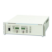
Ametek 2003RP User And Programming Manual (126 pages)
AC Power Source
Brand:
Ametek
| Category:
Power Supply
| Size: 1.45 MB
Table of Contents
Contact Information
3
Important Safety Instructions
5
Safety Symbols
5
Table of Contents
7
1 Introduction
11
General Description
11
Accessory Equipment/Rack Slides
11
Table 1-1: Available Models
11
2 Specifications
12
Electrical
12
Figure 2-1: Available RMS Current as Function of Output Voltage and Frequency
14
Supplemental
15
Measurements [Option]
16
System Specification
17
Unit Protection
18
Mechanical
18
Environmental
19
Regulatory
19
Front Panel Controls
20
Available Options
21
Figure 2-2: Rack Mount Slides (-RMS Option) Position
21
3 Installation and Functional Test
22
Unpacking
22
Power Requirements
22
Figure 3-1: Model 2003RP AC Power Source
22
Figure 3-2: Rear Panel View
23
Input Voltage Range Selection
24
Mechanical Installation
27
Input Wiring
27
Figure 3-5: Rack Mount Slides (-RMS Option) Position
27
Output Connections
28
Figure 3-6: Input and Output Wiring
29
Table 3-1: Maximum Output Wiring Lengths
29
Output Voltage Ranges
30
Functional Test
31
Other Modes of Operation
32
Figure 3-7: Test Setup 2003RP
32
4 Front Panel Operation
33
Functional Controls
33
Figure 4-1: Front Panel View
33
Figure 4-2: Voltage Auto Range Switch over Points
35
Figure 4-3: Control Knob
36
Control Knobs
36
How to Examples
38
Setting the Power on Initialization Values
41
Table 4-1: Factory Default Power on Settings
41
Current Limit Modes
42
Function Strobe [Option]
42
Remote Inhibit [Option]
43
5 Principle of Operation
44
General
44
Overall Description
44
DC Supply
44
Figure 5-1: AC Power System Block Diagram
45
Mother Board
47
Amplifier Modules
47
Oscillator Module
47
Range/Relay Board
47
Output Board
48
IEEE 488/RS232 Interface [Option]
48
6 Calibration
50
Calibration Equipment
50
Table 6-1: Load Resistors and Current
50
Selecting Calibration Mode
51
Table 6-2: CAL Mode Status LED Indicators
51
Routine Calibration
52
Figure 6-1: Test Equipment Hookup for Routine Output and Voltage Measurement Calibration
52
Figure 6-2: Test Equipment Hook-Up for Current and Power Measurement Calibration
53
Non-Routine Calibration
56
Figure 6-3: Internal Adjustments
58
7 Service
60
General
60
Cleaning
60
Basic Operation
60
Table 7-1: Basic Symptoms
60
Table 7-2: Poor Output Voltage Accuracy
60
Table 7-3: Poor Output Voltage Regulation
61
Table 7-4: Distorted Output
61
Table 7-5: Unit Shuts down after 3-5 Seconds
61
Table 7-6: no Output and no Lights on Front Panel
61
Table 7-7: no Output but "Display" Is on
62
Module Removal
63
Figure 7-1: Assembly Location
64
Replaceable Parts
66
Table 7-8: Replaceable Parts
66
Table 7-9: Fuses
67
8 Remote Control
68
Introduction
68
PGUI32 Program Requirements
68
Figure 8-1: Rear Panel View
69
IEEE Interface
70
Figure 8-2: GPIB Address Selection Switch
70
RS232C Interface
71
PGUI32 Setup and Installation
73
Figure 8-3: RS232C Interface Cable Wiring Diagram
73
Troubleshooting - RS232C
75
Figure 8-4: System Properties Dialog Box
76
Figure 8-5: COM Port Properties Dialog Box
76
Figure 8-6: Advanced Port Settings Dialog Box
76
Troubleshooting - IEEE-488 / GPIB
78
Figure 8-7: ni AT-GPIB/TNT Settings
78
Figure 8-8: ni AT-GPIB/TNT Advanced Settings Dialog
78
PGUI32 Distribution Files
80
Software Registration
81
9 Introduction to SCPI
82
Conventions Used in this Manual
82
The SCPI Commands and Messages
82
Figure 9-1: Partial Command Tree
83
Using Queries
84
Structure of a SCPI Message
84
Figure 9-2: Command Message Structure
85
SCPI Data Formats
87
Bus Throughput and Timing Considerations
87
10 SCPI Command Reference
88
Subsystem Commands
88
Calibration Subsystem
89
Measurement Subsystem
93
Instrument Subsystem
96
Source Subsystem
97
Output Subsystem
100
Limit Subsystem
104
Display Subsystem
105
Table 10-1: Mode Command Encoding
105
System Commands
106
Common Commands
108
Table 10-2: Bit Configuration of Standard Event Status Enable Register
109
Table 10-3: Bit Configuration of Standard Event Status Register
110
Table 10-4: *RST Default Parameter Values
112
Table 10-5: Status Registers - Power on Conditions
112
Table 10-6: Bit Configuration of Status Byte Register
113
11 Programming Examples
114
Introduction
114
Bus Throughput and Timing Considerations
114
Making Measurements
116
12 Status Registers
118
Power-On Conditions
118
Figure 12-1: AC Source Status System Model
118
Standard Event Status Group
119
Status Byte Register
119
Examples
120
Appendix A: SCPI Command Tree
121
Appendix B: SCPI Conformance Information
122
Appendix C: Error Messages
123
Table 12-1: Bus Error Messages
123
Index
124
Advertisement
Advertisement
Related Products
Ametek 2000L
Ametek Thermox 2000 ATEX Series
Ametek 200 Series
Ametek Crystal Pressure 200BARXP2I-DD
Ametek NetWave 20.1
Ametek Ortec radEAGLET-R 2SG-P-E
Ametek Ortec radEAGLET-R 2SG-H-P-E
Ametek 24-965FR100T
Ametek 24-1050FR80T
Ametek mocon OX-TRAN 2/48
Ametek Categories
Measuring Instruments
Test Equipment
Power Supply
Controller
Laboratory Equipment
More Ametek Manuals
Login
Sign In
OR
Sign in with Facebook
Sign in with Google
Upload manual
Upload from disk
Upload from URL