
Related Manuals for Ametek Sorensen XFR 7.5-300


Summary of Contents for Ametek Sorensen XFR 7.5-300
- Page 1 XFR 2800 Watt Series Programmable DC Power Supply XFR 7.5-300 XFR 12-220 XFR 20-130 XFR 33-85 XFR 40-70 XFR 60-46 XFR 100-28 XFR 150-18 XFR 300-9 XFR 600-4 TM-F2OP-C1XN Rev E www.programmablepower.com...
- Page 2 About AMETEK AMETEK Programmable Power, Inc., a Division of AMETEK, Inc., is a global leader in the design and manufacture of precision, programmable power supplies for R&D, test and measurement, process control, power bus simulation and power conditioning applications across diverse industrial segments.
- Page 3 This page intentionally left blank.
-
Page 4: Important Safety Instructions
Neither AMETEK Programmable Power Inc., San Diego, California, USA, nor any of the subsidiary sales organizations can accept any responsibility for personnel, material or inconsequential injury, loss or damage that results from improper use of the equipment and accessories. - Page 5 This page intentionally left blank.
- Page 6 AMETEK will, at its expense, deliver the repaired or replaced Product or parts to the Buyer. Any warranty of AMETEK will not apply if the Buyer is in default under the Purchase Order Agreement or where the Product or any part...
- Page 7 This page intentionally left blank.
-
Page 8: Table Of Contents
Contents Important Safety Instructions - - - - - - - - - - - - - - - - - - - - - - - - - - - - - - - - - - v 1 Features and Specifications Description - - - - - - - - - - - - - - - - - - - - - - - - - - - - - - - - - - - - - - - - - - - - - - - - - -1–2 Features and Options - - - - - - - - - - - - - - - - - - - - - - - - - - - - - - - - - - - - - - - - - - -1–3 Front Panel Controls- - - - - - - - - - - - - - - - - - - - - - - - - - - - - - - - - - - - - - - - - - - -1–3... - Page 9 Contents Load Connection - - - - - - - - - - - - - - - - - - - - - - - - - - - - - - - - - - - - - - - - - - - - - 2–12 Load Wiring - - - - - - - - - - - - - - - - - - - - - - - - - - - - - - - - - - - - - - - - - - - - - 2–12 Insulation Rating - - - - - - - - - - - - - - - - - - - - - - - - - - - - - - - - - - - - - - - 2–12 Current Carrying Capacity - - - - - - - - - - - - - - - - - - - - - - - - - - - - - - - - - 2–12...
- Page 10 Contents Configuring Multiple Supplies for Split Supply Operation - - - - - - - - - - - - - - 3–15 Two Positive Voltages - - - - - - - - - - - - - - - - - - - - - - - - - - - - - - - - - - - - 3–15 Positive-negative Supply - - - - - - - - - - - - - - - - - - - - - - - - - - - - - - - - - - 3–16 Over Temperature Protection (OTP) - - - - - - - - - - - - - - - - - - - - - - - - - - - - - - - - 3–17 4 Remote Operation...
- Page 11 Contents A Specifications Electrical Specifications - - - - - - - - - - - - - - - - - - - - - - - - - - - - - - - - - - - - - - - - A–2 Additional Specifications - - - - - - - - - - - - - - - - - - - - - - - - - - - - - - - - - - - - - - - A–6 Input Conditions - - - - - - - - - - - - - - - - - - - - - - - - - - - - - - - - - - - - - - - - - - - - - A–7 Additional Features - - - - - - - - - - - - - - - - - - - - - - - - - - - - - - - - - - - - - - - - - - - A–8...
- Page 12 Figures Figure 1-1 Power Supply Front Panel- - - - - - - - - - - - - - - - - - - - - - - - - - - - - - - - - 1–4 Figure 1-2 Power Supply Rear Panel (Low voltage (7.5 V to 100 V) model shown.) - 1–5 Figure 1-3...
- Page 14 Tables Table 1-1 Available Voltage and Current Ranges - - - - - - - - - - - - - - - - - - - - - - - - 1–2 Table 1-2 Rear Panel SW1 Switch Assignments - - - - - - - - - - - - - - - - - - - - - - - - - 1–6 Table 1-3 Rear Panel J2 Connector Terminals and Functions - - - - - - - - - - - - - - - - 1–8 Table 2-1...
-
Page 16: Features And Specifications
Features and Specifications Chapter 1 describes the XFR 2800 Watt Series Programmable DC Power Supply and lists the features. -
Page 17: Description
Features and Specifications Description This series of power supplies provides low noise, precisely regulated, variable DC output at 2800 watts of output power. Over voltage protection (OVP) and thermal shutdown are standard. Front panel controls and indicators are extensive. Select from several remote control choices: standard analog programming, optional isolated programming or readback, and optional GPIB programming or RS-232 control. -
Page 18: Features And Options
Features and Options Features and Options • Simultaneous digital display of both voltage and current. • Ten-turn front panel voltage and current controls for high resolution setting of the output voltage and current from zero to the rated output. • Automatic mode crossover into current or voltage mode. -
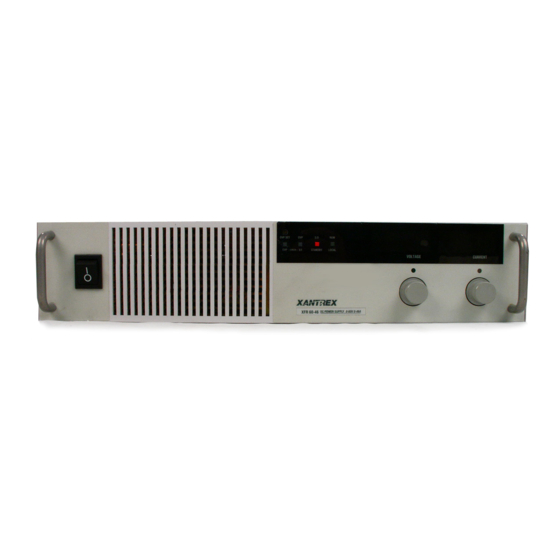
Page 19: Figure 1-1 Power Supply Front Panel
Features and Specifications 13 14 Figure 1-1 Power Supply Front Panel Description OVP Check: OVP Setting Preview Switch (See page 3–7 for more information.) OVP Set: OVP Adjust Potentiometer (See page 3–7 for more information.) V/I Check: Local Voltage & Current Limit Setting Preview Switch (See page 2–9 for more information.) OVP Shutdown LED S/D: Shutdown LED... -
Page 20: Rear Panel Connectors And Switch
Rear Panel Connectors and Switch Rear Panel Connectors and Switch Use the rear panel SW1 Programming, Monitoring, and Shutdown Select switch and the rear panel J2 Programming and Monitoring connector to choose among several remote programming and monitoring options. See Figure 1-2 for switches and connectors available at the rear panel. -
Page 21: Rear Panel Sw1 Switch
Features and Specifications Rear Panel SW1 Switch The SW1 Programming, Monitoring, and Shutdown Select switch is an 8-position piano DIP switch located on the power supply’s rear panel. See Figure 1-3. The SW1 switch enables you to choose: • Resistive programming of output voltage or current limit •... -
Page 22: Resetting The Switches
Rear Panel Connectors and Switch Resetting the Switches Before making any changes to the switch settings, disable the power supply output by pushing the front panel STANDBY switch to its IN position. This temporarily shuts down the power supply. The front panel S/D LED turns on. -
Page 23: Table 1-3 Rear Panel J2 Connector Terminals And Functions
Features and Specifications Table 1-3 Rear Panel J2 Connector Terminals and Functions Connector Reference Name Function J2-1 VRMT Remote Output Voltage Selects remote output voltage Programming Select programming when jumpered to pin 3. J2-2 IRMT Remote Output Current Limit Selects remote output current limit Programming Select programming when jumpered to pin 3. -
Page 24: Making J2 Connections
Rear Panel Connectors and Switch Making J2 Connections CAUTION Do not attempt to bias program/monitor signal return (J2 terminals 5, 7, 9, and 11) relative to the supply output because control ground (J2-3) and the program/ monitor signal returns are at the same potential as the power supply return in a standard unit. - Page 25 1-10...
-
Page 26: Installation
Installation Chapter 2 provides recommendations and procedures for inspecting, installing, and testing the power supply. -
Page 27: Basic Setup Procedure
Installation Basic Setup Procedure See Table 2-1 for a summary of the basic setup procedure and an overall view of the subsections in Chapter 2. Use the procedure as a quick reference if you are familiar with the installation requirements for the power supply. -
Page 28: Inspection, Cleaning, And Packaging
Inspection, Cleaning, and Packaging Inspection, Cleaning, and Packaging Initial Inspection When you first receive your unit: 1. Inspect the unit for scratches and cracks, and for broken switches, connectors, and displays. 2. Ensure that the packing box contains the AC input cover and strain relief kit (see Figure 2-2). -
Page 29: Location, Mounting, And Ventilation
Installation 5. If storing, stack no more than eight cartons high. Check the storage temperature range and storage altitude specification in “Environmental Specifications” on page A–9. POWER SUPPLY Model Number: Serial Number: FRAGILE — ELECTRONIC EQUIPMENT Figure 2-1 Shipping or Storage Carton Label Location, Mounting, and Ventilation Use the power supply in rack-mounted or benchtop applications. -
Page 30: Ventilation
AC Input Power Ventilation Whether you place the power supply in a rack or on a bench, allow cooling air to reach the ventilation inlets on the front and sides of the unit and allow 4 in. (10 cm) of unrestricted air space at the rear of the unit for the fan exhaust. -
Page 31: Ac Input Connector And Voltage Selection
Installation AC Input Connector and Voltage Selection The AC input connector is a 3-terminal wire clamp located on the power supply’s rear panel. See Figure 2-2 on page 2–8. See Table 2-2 for the input voltage ranges and frequency required to operate the power supply. Table 2-2 Operation AC Input Voltage Range and Frequency AC Voltage Range Frequency... -
Page 32: Ac Input Wire Connection
AC Input Power AC Input Wire Connection WARNING: Shock hazard Ensure that the chassis ground screw does not penetrate more than 3/8 in. (9 mm) into the rear panel of the unit. 1. Strip the outside insulation on the AC cable approximately 4 in. (10 cm). -
Page 33: Figure 2-2 Ac Input Cover And Strain Relief
Installation Chassis Ground Screw Screw-on Locknut Stripped Wire Installed in Strain Relief Cover Flat Washer (2 places) Assembled Strain Lock Washer (2 places) Relief Screw (2 places) Connector Terminal Locations Figure 2-2 AC Input Cover and Strain Relief TM-F2OP-C1XN-01... -
Page 34: Functional Tests
Functional Tests Functional Tests These functional test procedures include power-on and front panel function checks as well as voltage and current mode operation checks. Refer to front and rear panel diagrams in “Front Panel Controls” on page 1–3 and “Rear Panel Connectors and Switch” on page 1–5. Equipment Required •... -
Page 35: Voltage Mode Operation Check
Installation Voltage Mode Operation Check 1. Ensure the voltage and current controls on the front panel are turned fully counter-clockwise. 2. Connect that the output sense lines are connected in the default configuration. (The local sense lines are connected between terminals 1 and 2 and between terminals 4 and 5 on the J10 sense connector as shown on the rear panel diagram in Figure 1-2 on page 1–5.) -
Page 36: Front Panel Function Checks
Functional Tests Front Panel Function Checks 1. Turn the front panel AC switch to ON. 2. Set voltage and current controls fully clockwise. Push the STANDBY switch to its IN position and check that the voltmeter reading falls to zero and the red S/D (Shutdown) LED turns on. Push the STANDBY switch once again to reset it to its OUT position. -
Page 37: Load Connection
Installation Load Connection This section provides recommendations for load wires and how to connect them for both single and multiple load configurations. Load Wiring WARNING Ensure that the chassis ground screw does not penetrate more than 3/8 in. (9 mm) into the rear panel of the unit. -
Page 38: Load Wiring Length For Operation With Sense Lines
Load Connection Table 2-4 Current Carrying Capacity for Load Wiring Wire Size Wire Size (AWG) Maximum Current (A) (AWG) Maximum Current (A) Load Wiring Length for Operation with Sense Lines For applications using remote sensing, you must limit the voltage drop across each load wire. -
Page 39: Noise And Impedance Effects
Installation Noise and Impedance Effects To minimize noise pickup or radiation, use shielded pair wiring of the shortest possible length for load wires. Connect the shield to the chassis via a rear panel mounting screw. Where shielding is impossible or impractical, simply twisting the wires together will offer some noise immunity. -
Page 40: Figure 2-4 Output Strain Relief And Cover
Load Connection Screw, Lock Washer, and Flat Washer (3 places) Keps Nut and Flat Washer (3 places) Wire Clamp and Screw Strain Relief Chassis Cover Top Cover Figure 2-4 Output Strain Relief and Cover TM-F2OP-C1XN-01 2-15... -
Page 41: 7.5 V To 100 V Models
Installation 7.5 V to 100 V Models The 7.5 V to 100 V models are equipped with output bus bars. To make a typical load connection to a 7.5 V, 300 A power supply: 1. Strip the ends of the wires. 2. -
Page 42: 150 V To 600 V Models
Load Connection 150 V to 600 V Models WARNING: Shock hazard To protect personnel against accidental contact with hazardous voltages, ensure that the load, including connections, has no live parts which are accessible. Also ensure that the insulation rating of the load wiring and circuitry is greater than or equal to the maximum output voltage of the power supply. -
Page 43: Inductive Loads
Installation Inductive Loads To prevent damage to the power supply from inductive kickback, connect a diode across the output. The diode must be rated at greater than or equal to the supply’s output voltage and have a current surge rating greater than or equal to the supply’s output rating. -
Page 44: Connecting Multiple Loads
Load Connection Figure 2-8 Single Load with Remote Sensing Connecting Multiple Loads Proper connection of distributed loads is an important aspect of power supply use. Two common methods of connection are the parallel power distribution method and the radial power distribution method. Parallel Power Distribution This distribution method involves connecting leads from the power supply to one load, from that load to the next load, and so on for each load in the system. -
Page 45: Figure 2-9 Multiple Loads With Local Sensing
Installation Figure 2-9 Multiple Loads with Local Sensing Figure 2-10 Multiple Loads with Remote Sensing 2-20 TM-F2OP-C1XN-01... -
Page 46: Local And Remote Sensing
Local and Remote Sensing Local and Remote Sensing Use connections at the rear panel J10 sense connector to configure the power supply for local or remote sensing of output voltage. See Figure 2- 11 for a drawing of the sense connector. Sense Wiring WARNING: Shock hazard There is a potential shock hazard at the sense connector when using a power supply... -
Page 47: Figure 2-11 J10 Sense Connector
Installation Figure 2-11 J10 Sense Connector (Shown with local sense jumpers connected) Table 2-5 Rear Panel J10 Sense Connector Terminals and Functions Terminal Name Function J10-1 Return Sense (–SNS) Remote negative sense connection. Default connection to terminal 2. J10-2 Negative Output (Return Connected internally to negative bus bar. -
Page 48: Using Remote Sensing
Local and Remote Sensing Using Remote Sensing WARNING: Shock hazard There is a potential shock hazard at the sense points when using a power supply with a rated output greater than 40 V. Ensure that connections at the load end are shielded to prevent contact with hazardous voltages. -
Page 49: Figure 2-12 Connecting Remote Sense Lines
Installation 4. To prevent ground loops, ground the sense line shield, at one point only, to the power supply’s return output connection at the load, to the power supply’s return output at its negative output terminal, or to the power supply’s chassis. 5. -
Page 50: Local Operation
Local Operation Chapter 3 provides procedures for local (front panel) operation. It includes procedures for using over voltage protection, shutdown function, multiple supplies, and over temperature protection. -
Page 51: Introduction
Local Operation Introduction Once you have installed the power supply and have connected both the AC input power and the load as covered in Chapter 2, “Installation”, the power supply is ready to operate in local control mode (that is, operation at the unit’s front panel). -
Page 52: Standard Operation
Standard Operation Standard Operation This power supply has two basic operating modes: Constant Voltage Mode and Constant Current Mode, and two control modes: Local Control Mode (default setting) and Remote Programming Mode. Both operating modes are available regardless of which control mode is used. Operating Modes and Automatic Crossover Whether controlled by local or remote programming, the power supply has two basic operating modes: Constant Voltage Mode and Constant... -
Page 53: Constant Voltage Mode Operation
Local Operation Constant Voltage Mode Operation The power supply will operate in constant voltage mode whenever the load current I is less than the current limit setting I , or: I < I (Note: I In constant voltage mode, the power supply maintains the output voltage at the selected value (V ) while the load current I varies with the load... -
Page 54: Shipped Configuration (Local Control Mode)
Standard Operation Shipped Configuration (Local Control Mode) The factory ships units already configured for local control (front panel) operation. See Table 3-1 for a summary of this configuration. See Figure 1-4 on page 1–7 and Figure 1-2 on page 1–5 for front and rear panel diagrams. -
Page 55: Setting Output Voltage And Current Limit
Local Operation Setting Output Voltage and Current Limit Install the power supply and connect the load as described in “Installation”. Ensure that the power supply is set up for local control as described in “Shipped Configuration (Local Control Mode)” on page 3–5. Then, set the output voltage and current limit at the front panel with the following procedure. -
Page 56: Using Over Voltage Protection (Ovp)
Using Over Voltage Protection (OVP) Using Over Voltage Protection (OVP) The OVP circuit protects the load in the event of a remote programming error, an incorrect voltage control adjustment, or a power supply failure. The protection circuit monitors the output voltage at the output of the power supply and will shut down the main power converter whenever a preset voltage limit is exceeded. -
Page 57: Resetting The Ovp Circuit
Local Operation 7. To check that the power supply shuts off at the desired set point, slowly increase the output voltage while monitoring the front panel voltmeter. The OVP LED on the front panel turns on when the OVP circuit activates. Resetting the OVP Circuit To reset the OVP circuit after it activates: 1. -
Page 58: Using The Shutdown Function
Using the Shutdown Function Using the Shutdown Function Use the Shutdown function to disable or enable the supply’s output so that you can make adjustments to either the load or the power supply without shutting off the power supply. Activate this function from the front panel at any time by using the STANDBY switch. -
Page 59: Table 3-2 Switch Settings For Shutdown Circuit Logic
Local Operation Table 3-2 Switch Settings for Shutdown Circuit Logic Source Signal Supply Switch SW1-7 Setting Signal Level Output S/D LED OFF (OPEN) 2-15 V HIGH (Active low, default) 0-0.4 V ON (CLOSED) 2-15 V HIGH (Active high) 0-0.4 V Notes: 1. -
Page 60: Using Multiple Supplies
Using Multiple Supplies Using Multiple Supplies WARNING There is a shock hazard at the load when using a power supply with a rated or combined output greater than 40 V. To protect personnel against accidental contact with hazardous voltages created by series connection, ensure that the load, including connections, has no live parts which are accessible. -
Page 61: Configuring Multiple Supplies For Series Operation
Local Operation Configuring Multiple Supplies for Series Operation CAUTION Do not use remote sensing during series operation. CAUTION The maximum allowable sum of the output voltages is 600 Vdc. Use series operation to obtain a single higher voltage output using two or more supplies. -
Page 62: Configuring Multiple Supplies For Parallel Operation
Using Multiple Supplies Configuring Multiple Supplies for Parallel Operation Use parallel operation to obtain a higher current through a single output using two or more supplies. Set all of the OVP setpoints to maximum. (See “Using Over Voltage Protection (OVP)” on page 3–7.) Set all of the outputs to the same voltage before connecting the positive (+) output terminals and negative (–) output terminals in parallel. -
Page 63: Sensing For Parallel Operation
Local Operation Sensing for Parallel Operation Use default local sensing to enhance power sharing between units, as the impedance of the load lines will tend to correct for current imbalance. If you use remote sensing at the load for better voltage regulation, one supply always operates in current limit mode and supplies most of the power. -
Page 64: Configuring Multiple Supplies For Split Supply Operation
Using Multiple Supplies Configuring Multiple Supplies for Split Supply Operation Split supply operation uses two power supplies to obtain two positive voltages with a common ground, or to obtain a positive-negative supply. Two Positive Voltages To obtain two positive voltages, connect the negative output terminals of both supplies together in a common connection. -
Page 65: Positive-Negative Supply
Local Operation Positive-negative Supply CAUTION To prevent possible damage to the supply, do not connect the remote program return line of the negative supply to the common connection. To obtain a positive-negative supply, connect the negative output terminal of one supply to the positive output terminal of the second supply. The positive output terminal of the first supply then provides a positive voltage relative to the common connection while the negative output terminal of the second supply provides a negative voltage. -
Page 66: Over Temperature Protection (Otp)
Over Temperature Protection (OTP) Over Temperature Protection (OTP) The OTP function allows you to select how the power supply recovers from an over temperature shutdown using the rear panel switch SW1-8. See Table 3-3 for switch settings and selections. See “Rear Panel Connectors and Switch”... - Page 67 3-18...
-
Page 68: Remote Operation
Remote Operation Chapter 4 details remote analog programming operation and remote monitoring of output voltage and current. -
Page 69: Introduction
Remote Operation Introduction The rear panel switches and connector on the power supply allow you to program the supply with an analog device or to output readback signals. This section covers the following topics: • See “Remote Analog Programming of Output Voltage and Current Limit”... -
Page 70: Remote Analog Programming Of Output Voltage And Current Limit
Remote Analog Programming of Output Voltage and Current Limit Remote Analog Programming of Output Voltage and Current Limit Remote analog programming allows control of the power supply’s output voltage and/or current limit to shift from local operation at the front panel voltage and current controls to external analog sources. - Page 71 Remote Operation To set up remote analog programming: 1. Turn the power supply OFF. 2. Using Table 4-2, set switches SW1-1, SW1-2, SW1-3, and SW1-4 according to the selected programming sources. See the Notes at the end of this procedure for more information about switch settings. 3.
-
Page 72: Table 4-2 Power Supply Settings For Different Programming Sources
Remote Analog Programming of Output Voltage and Current Limit Table 4-2 Power Supply Settings for Different Programming Sources Output Current Limit Programming Source Output Voltage Programming None (Front Source 0-5 Vdc 0-10 Vdc 0-5 k Resistor 0-10 k Resistor Panel Control) SW1: set 3 and 4 SW1: set 3 open. -
Page 73: Figure 4-1 Connecting Programming Sources To J2 Connector
Remote Operation Figure 4-1 Connecting Programming Sources to J2 Connector TM-F2OP-C1XN-01... -
Page 74: Remote Monitoring Of Output Voltage And Current
Remote Monitoring of Output Voltage and Current Remote Monitoring of Output Voltage and Current Readback Signals The J2 connector on the rear panel provides access to calibrated readback signals for remote monitoring of the output voltage and current. Rear panel switches SW1-5 and SW1-6 allow you to select either a 0-5 Vdc or a 0-10 Vdc range for the output. -
Page 76: Calibration And Troubleshooting
Calibration and Troubleshooting Chapter 5 details remote analog programming operation and remote monitoring of output voltage and current. It also provides troubleshooting information. -
Page 77: Calibration Setup
Calibration and Troubleshooting WARNING: Shock hazard Exercise caution when using and calibrating a power supply. High energy levels can be stored at the output voltage terminals on a power supply in normal operation. In addition, potentially lethal voltages exist in the power circuit and on the output and sense connectors of a power supply with a rated output greater than 40 V. -
Page 78: Accessing Calibration Potentiometers
Calibration Setup Accessing Calibration Potentiometers WARNING: Shock hazard Disconnect AC power from the unit before removing the cover. Even when the front panel power switch is in the OFF position, live line voltages are exposed when the cover is removed. Repairs and adjustments must be made by experienced service technicians only. -
Page 79: Figure 5-1 Programming And Monitoring Calibration Locations
Calibration and Troubleshooting Figure 5-1 Programming and Monitoring Calibration Locations (Top view) TM-F2OP-C1XN-01... -
Page 80: Calibrating For Programming Accuracy
Calibrating for Programming Accuracy Calibrating for Programming Accuracy The factory calibrates the offset and range of the voltage and current programming circuits to within 1% for the default 0-10 Vdc programming signals. You may need to recalibrate when you use 0-5 Vdc programming or when you switch back to 0-10 Vdc programming after previously calibrating for 0-5 Vdc programming. -
Page 81: Current Limit Programming Circuit Calibration
Calibration and Troubleshooting Current Limit Programming Circuit Calibration To perform current limit programming circuit calibration: 1. Ensure that the power supply is turned OFF. Disconnect any load. 2. Connect the program source between J2 connector terminals 8 (output current limit programming input) and 7 (current program signal return). -
Page 82: Calibrating For Readback Accuracy
Calibrating for Readback Accuracy Calibrating for Readback Accuracy The factory calibrates the offset and range of the output voltage and current monitor circuits to within 1% for the default 0-10 Vdc scales. You may need to recalibrate when you select the 0-5 Vdc scale or when you switch back to the 0-10 Vdc scale after previously calibrating for 0-5 Vdc operation. -
Page 83: Output Current Monitor Circuit Calibration
Calibration and Troubleshooting Output Current Monitor Circuit Calibration To perform output current monitor circuit calibration: 1. Ensure that the power supply is turned OFF. Disconnect any load. 2. Set SW1 switch 6 OPEN to select 0-5 V output current monitor range, CLOSED for 0-10 V. -
Page 84: User Diagnostics
User Diagnostics User Diagnostics If your power supply is not performing as described in this operating manual, run through the procedures and checks in this section before calling your service technician. These procedures are confined to operator-level functions only and do not require cover-off servicing. Emergency Shutdown In an emergency, carry out both of these steps: 1. -
Page 85: Troubleshooting For Operators
Calibration and Troubleshooting Troubleshooting for Operators Use the checks in Table 5-1 to ensure that the power supply is configured and connected for normal operation. Abbreviated References Used in Table AC Fail over temperature protection over voltage protection remote mode shutdown Table 5-1 User Diagnostics Symptom... - Page 86 User Diagnostics Table 5-1 User Diagnostics Symptom Check Further Checks and Corrections Output not Is unit in current limit mode? Turn current knob clockwise to adjustable. (Red Current Mode LED turned on.) increase current limit. Reduce load if current is at maximum. See page 3–6. Is unit in remote mode? If using remote analog control, check (Green REM LED turned on.)
- Page 87 5-12...
- Page 88 Specifications Appendix A contains electrical, mechanical and environmental specifications and characteristics of the XFR 2800 Watt Series Programmable DC Power Supply. These specifications are warranted over a temperature range of 0 °C to 50 °C. Nominal ambient temperature assumed is 25 °C. Nominal line voltages are 120 Vac and 230 Vac.
-
Page 89: Electrical Specifications
Specifications Electrical Specifications These specifications are warranted over a temperature range of 0 °C to 50 °C. Nominal ambient temperature assumed is 25 °C. Nominal line voltage is 208 Vac, 60 Hz. See Table A-1 and Table A-2 for maximum values for model-dependent specifications. - Page 90 Electrical Specifications Table A-1 Specifications for 7.5 V to 40 V Models Models 7.5-300 12-220 20-130 33-85 40-70 Drift (8 hours): Voltage (0.05% of Vmax) 3.75 mV 6 mV 10 mV 16.5 mV 20 mV Current (0.05% of Imax) 150 mA 110 mA 65 mA 42.5 mA...
-
Page 91: Table A-2 Specifications For 60 V To 600 V Models
Specifications Table A-2 Specifications for 60 V to 600 V Models Models 60-46 100-28 150-18 300-9 600-4 Output Ratings: Output Voltage 0-60 V 0-100 V 0-150 V 0-300 V 0-600 V Output Current 0-46 A 0-28 A 0-18 A 0-9 A 0-4 A Output Power 2760 W... - Page 92 Electrical Specifications Table A-2 Specifications for 60 V to 600 V Models Models 60-46 100-28 150-18 300-9 600-4 Temperature Coefficient: Voltage (0.02% of Vmax/°C) 12 mV 20 mV 30 mV 60 mV 120 mV Current (0.03% of Imax/°C) 13.8 mA 8.4 mA 5.4 mA 2.7 mA...
-
Page 93: Additional Specifications
Specifications Additional Specifications Rise Time (No Load, Full Load): 7.5 V to 60 V models: 100 ms; 100 V to 600 V models: 170 ms Fall Time (No Load): Fall Time (Full Load): 7.5 V to 60 V models: 100 ms; 100 V to 600 V models: 170 ms Voltage Mode Transient <3 ms... -
Page 94: Input Conditions
Input Conditions Input Conditions Rated AC Input Voltage 200/208/220/230/240 Vac (nominal) Maximum AC Input Power 5000 VA Operational AC Input Voltage 190-264 Vac , 1φ (24.3 A maximum at 208 Vac; 22.4 A maximum at 230 Vac.) Auto range select function. Input Frequency Range 47-63 Hz Power Factor... -
Page 95: Additional Features
Specifications Additional Features Switching Frequency nominal 31 kHz (62 kHz output ripple). Output Hold-up Time Greater than 10 ms with interruption of AC line, for nominal AC input and full load. Maximum Voltage Differential ±600 Vdc from either output to safety ground Insulation Resistance Input to chassis: >30 MΩ, with 500 Vdc;... -
Page 96: Environmental Specifications
Environmental Specifications Environmental Specifications Operating Temperature Range 0 °C to 50 °C. Storage Temperature Range -20 °C to +70 °C 30% to 60% RH non-condensing Humidity Range Operating Altitude Up to 6,500 feet (2000 m) Storage Altitude Up to 50,000 feet (15 000 m) Installation Category Intended for use in installation category (over voltage category) II (IEC 1010-1... -
Page 97: Mechanical Specifications
Specifications Mechanical Specifications Front Panel V and I Control 10-turn voltage and current potentiometers Front Panel Voltage Control 0.02% of maximum voltage Resolution Front Panel Voltage and Current 3.5-digit green numeric LED displays. For Meters accuracy specifications, see Table A-1 on page A–2 and Table A-2 on page A–4. - Page 98 Mechanical Specifications Mounting Rack mount brackets. Mount at front panel. Weight Approximately 33lb. (15 kg) Approvals CE mark: Meets EMC standards EN50081-2 and EN50082-2 and safety standard IEC1010-1 c(UL)us: UL certified to UL3111-1, 1st edition and to CAN/CSA C22.2 No. 1010.1-92 FCC: Meets Class A limits of Part 15 subpart B...
-
Page 99: Figure A-2 Dimensional Drawings
Specifications 19 in. (483 mm) 3.45" (87.63 mm) 16.9in. (429 mm) 20.975in. (533 mm) 17.475 in. (444 mm) Figure A-2 Dimensional Drawings A-12 TM-F2OP-C1XN-01...
Need help?
Do you have a question about the Sorensen XFR 7.5-300 and is the answer not in the manual?
Questions and answers