Revolabs Fusion Setup Manual
Wireless microphone system
Hide thumbs
Also See for Fusion:
- User manual (15 pages) ,
- Setup manual addendum (9 pages) ,
- Setup manual (4 pages)
Table of Contents
Advertisement
Advertisement
Table of Contents

Related Manuals for Revolabs Fusion


Summary of Contents for Revolabs Fusion
- Page 1 Revolabs Fusion™ Wireless Microphone System Set-Up Guide Rev 1.12...
-
Page 2: Table Of Contents
Contents of Box Details About the Fusion Fusion Front Panel Fusion Back Panel Fusion Set-Up Audio-Conferencing Video-conferencing Configuration Pairing Microphones to Fusion Base Station Configuring Fusion with Video-conferencing Sta- 11 Polycom Installation Tandberg Installation Lifesize Installation Sony Installation Programming Port DIP Switches... - Page 3 You may connect to powered speakers, connect to existing speaker system or connect to a new room speaker system to hear the call. Decide on where you want to put the Fusion system, whether you want it vertical or horizontal, plug in the cables and you are ready to have great wireless audio in any conference room.
-
Page 4: Contents Of Box
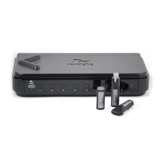
Set-Up Guide Contents of box: Fusion Base Station and four or eight wireless microphones (any type) AC power adapter for Base Sta- Charger Base and AC wall adapter for Charger Base Remote Control Fusion Base Station vertical stand Cable A... -
Page 5: Details About The Fusion
Revolabs Fusion™ Details about the Fusion Fusion Front Panel The Revolabs Fusion Base Station, shown below in front and rear panel views, manages wireless audio signal processing, and pairing between the Solo microphones and the Fusion Base Station. 1. IR Remote receiver (if not in sight range of remote, page 22) 2. -
Page 6: Fusion Back Panel
6. Telephone Set-in RJ11 7. Audio Control RJ45 (Revolabs use only) 8. Programming Port: LEFT DIP Switches 1-8 (refer to page 18) 9. Programming Port: RIGHT DIP Switches 1-8 (Revolabs Use Only) 10. DB9 (Revolabs use only) 11. IR Remote DB9... -
Page 7: Fusion Set-Up
WARNING: Do not put Fusion Base Station behind metal doors. If you are putting the Fusion Base Station into a cabinet with non-metal doors, you need to use the Remote IR Sensor (part number 07-IRREMO-01) for remote to work. (Refer to page 22) -
Page 8: Audio-Conferencing
Plug speakers into wall outlet. Plug one end of Cable B, the phone line cable, into the Fusion Base Station <Line In>, plug other end into phone jack. You may also plug a phone into the RJ11 <Set In>, You may then dial with the remote control or the phone. -
Page 9: Pairing Microphones To Fusion Base Station
LED (make sure unit is first powered on by observing GREEN power LED on the front panel). When the microphone and Fusion Base Station are paired, both microphone and channel LEDs will flash RED as microphones are removed from the Charger Base and flash GREEN when un-muted. - Page 10 (muted audio). Pairing is now complete. The Fusion Base Station has four or eight indicator LED lights (one for each microphone) and pairing push buttons on the front panel. When the LED is flashing GREEN or RED, that channel is active and connected to a wireless microphone (GREEN is for live audio, RED is for muted).
- Page 11 The following pages have a representative sample of the most popular video-conferencing systems. If you cannot find your specific video-conferencing station and need assistance in configuring the cables, check the additional documentation in the FAQs or Technical Documentation sections on www.revolabs.com , or the video-conferencing station documentation. Page 11...
-
Page 12: Polycom Installation
Step 1 1. Plug the red RCA connector on one end of Cable C into Polycom video-station <Audio Out 1>, and then plug the red RCA connector on the other end into the Fusion Base Station <Conf In>. 2. Plug the black RCA connector on one end of Cable C into Polycom video-station <Audio In>, and then plug the black RCA connector on the other end into the Fusion Base Station... - Page 13 RCA connector on the other end into the Fusion Base Station <Conf Out>. 2. Plug the 3.5mm 3 pin cable into the Polycom video-station <Audio Out 1 Red>, and then plug the RCA connector on the other end into the Fusion Base Station <Conf In>. configure the Polycom HDX 9000 Series system: Select the button from the main screen to access the System menu.
-
Page 14: Lifesize Installation
1. Plug the red RCA connector on one end of Cable C into Lifesize video-station <Audio Out 1>, and then plug the red RCA connector on the other end into the Fusion Base Station <Conf In>. 2. Plug the black RCA connector on one end of Cable C into Lifesize video-station <Audio In>, and then plug the black RCA connector on the other end into the Fusion Base Station <Conf... -
Page 15: Sony Installation
2. Plug one XLR connector of Cable D, XLR to XLR, into XLR Female to 3.5mm adapter cable and then to the Sony video-station <Mic 1 Input> and the other XLR connector into the Fusion Base Station Mic Level Output <Conf Out (Mics)>. - Page 16 1. Plug the black RCA connector on one end of Cable C into Tandberg video-station <Audio Out 1>, and then plug the black RCA connector on the other end into the Fusion Base Station <Conf In>. The other RCA connector is not used.
- Page 17 2. Plug one XLR connector of Cable D, XLR to XLR, into XLR Female to 3.5mm adapter cable and then to the Sony video-station <Mic 1 Input> and the other XLR connector into the Fusion Base Station Mic Level Output <Conf Out (Mics)>.
- Page 18 1. Plug the black RCA connector on one end of Cable C into Tandberg video-station <Audio Out 1>, and then plug the black RCA connector on the other end into the Fusion Base Station <Conf In>. The other RCA connector is not used.
- Page 19 2. Plug the black RCA connector on one end of Cable C into Tandberg video-station <Audio Out 1>, and then plug the black RCA connector on the other end into the Fusion Base Station <Conf In>. The other RCA connector is not used.
-
Page 20: Programming Port Dip Switches
Set-Up Guide Programming Port: DIP Switches The Fusion Base Station factory default settings are all OFF. The left Programming Port (#8, page 6) is end-user configurable. Programming Port (#9, page 6) on the right is reserved for Revolabs Use Only. -
Page 21: Multiple Fusion Systems
Multiple Fusion Systems There are two settings that must be adjusted when more than one Fusion system is used within a 100’ (30.5 m) range: frequency and transmit power level. These settings will enable several Fusion systems to be used near each other, but not interfere with each other. -
Page 22: Tabletop Master Mute
Remote Control MUTE button will unmute all tabletop microphones. All wearable and handheld adapter microphones in use will return to their prior state. DIP switch #5 is ON (page 18). NOTE: The Fusion system must be powered off and back on for any DIP Switch changes to take effect. Page 20... -
Page 23: Auto Phone Answer
To answer a phone call and begin a teleconference, the user may use the Remote Control and press the “Call” key or the Fusion Base Station will automatically answer the call after two rings. DIP switch #6 is ON (page 18). NOTE: The Fusion system must be powered off and back on for any DIP Switch changes to take effect. Page 21... -
Page 24: Remote Ir Sensor
IR Sensor cable (part number: 07-IRREMO-01) must be used to position the Fusion IR Sensor outside of the cabinet. Plug the serial plug end into the IR Remote connector on the back panel of the Fusion Base Station (page 9), bring IR Sensor end out of cabinet, and secure with Velcro. -
Page 25: Hearing Assistance
Room Out RCA plug will no longer function in this mode; Aux Out will serve as Room Out. NOTE: The Fusion system must be powered off and back on for any DIP Switch changes to take effect. -
Page 26: Indicator Lights
Set-Up Guide Revolabs Fusion™ Indicator Lights Equipment Use Equipment Use Microphone LED Microphone LED Base Station Base Station Meaning Meaning LEDs LEDs Microphone in Microphone in Solid RED Solid RED Charging in Progress Charging in Progress Charger Base Charger Base... -
Page 27: Safety And Regulatory Information
Users are not permitted to make changes or modify the equipment in any way. Changes or modifications not expressly approved by Revolabs, Inc. could void the user’s authority to operate the equipment. To meet FCC and Industry Canada RF radiation exposure limits for general population (uncontrolled exposure), a minimum of 7.9 inches (20 cm) separation distance must be maintained between the Fusion Base Station and users' and/or nearby persons' bodies at all times. - Page 28 Revolabs Fusion™ NOTE: This equipment has been tested and found to comply with the limits for a Class B digital device, pursuant to part 15 of the FCC Rules. These limits are designed to provide reasonable protection against harmful interference in a residential installation.
-
Page 29: Industry Canada Notice To Users
01-FUSION-8CH-NA & 01-FUSION-4CH-NA North America UPCS Usage Restriction Due to the UPCS frequencies used, this product is licensed for operation only in the United States of America and Canada. -
Page 30: European Compliance
Revolabs Fusion Base Station, European 01-8FUSIONEU-62 Revolabs Fusion System with 6 tabletop omni & 2 wearable mics, European 01-4FUSIONEU-31 Revolabs Fusion Base System with 3 tabletop omni & 1 wearable mics, European 03-EXEMICEU-BLK-11 Revolabs Solo™ Executive Microphone 03-EXECHGEU-STD-11 Revolabs Solo™ Executive... -
Page 31: Specifications
1.88 to 1.90 GHz (DECT EU) Connectors: Fusion Base Station IR Remote Serial DB9 CD Programming Serial DB9 - for Revolabs use only Audio Control RJ45 – for Revolabs use only Telephone Line-In RJ11 Telephone Set-In RJ11 Network RJ45 – for Revolabs use only... -
Page 32: Warranty
Revolabs Fusion™ Warranty Revolabs, Inc. warrants this product to be free of manufacturing defects. Repair or replacement of any defective part or unit (at the discretion of the Seller) will be free of charge for the period of one year. - Page 33 Base Station prior to first use. © 2008 REVOLABS, INC. All rights reserved. No part of this document may be reproduced in any form or by any means without ex- press written permission from Revolabs, Inc. Product specifications are subject to change without notice.
Need help?
Do you have a question about the Fusion and is the answer not in the manual?
Questions and answers