Table of Contents
Advertisement
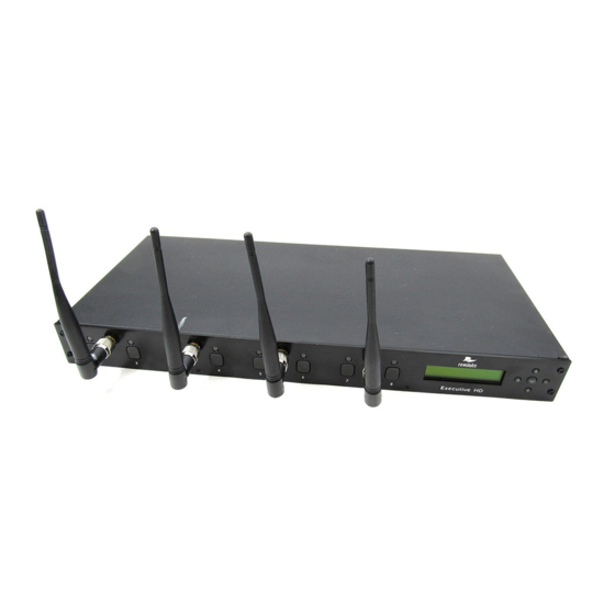
REVOLABS EXECUTIVE HD™
Wireless Microphone System
Models: 01-HDEXEC-NM, 01-HDEXEC4-NM, 01-HDEXEV-NM-AES,
01-HDEXEC4-NM-AES, 03-HDEXECEU-NM, 03-HDEXEC4EU-NM,
03-HDEXECEU-NM-AES, 03-DEXEC4EU-NM-AES,
03-HDEXECCN, 03-HDEXEC4CN, 03-HDEXECJP, 03-HDEXEC4JP,
03-HDEXECJP-AES & 03-HDEXEC4JP-AES
Installation and Operation Guide
Advertisement
Table of Contents

Related Manuals for Revolabs 01-HDEXEC-NM


Summary of Contents for Revolabs 01-HDEXEC-NM
- Page 1 REVOLABS EXECUTIVE HD™ Wireless Microphone System Models: 01-HDEXEC-NM, 01-HDEXEC4-NM, 01-HDEXEV-NM-AES, 01-HDEXEC4-NM-AES, 03-HDEXECEU-NM, 03-HDEXEC4EU-NM, 03-HDEXECEU-NM-AES, 03-DEXEC4EU-NM-AES, 03-HDEXECCN, 03-HDEXEC4CN, 03-HDEXECJP, 03-HDEXEC4JP, 03-HDEXECJP-AES & 03-HDEXEC4JP-AES Installation and Operation Guide...
-
Page 3: Table Of Contents
WEEE Notification: ........................... 5 2003/11/EC & 2002/95/EC “RoHS Compliance Directive”: ..............5 Introduction..............................6 System Components ..........................6 Installing the Revolabs Executive HD ™ Base Station ................. 7 Controls and Connections: ........................8 Configuring the Executive HD Base Station ....................9 Using Multiple Revolabs Executive HD Systems Together .............. -
Page 4: Safety And General Information
Safety and General Information Please read the following information to ensure safe and efficient use of your Revolabs system. FCC User Information FCC ID: T5V01HDEXEC Revolabs Executive HD™ Base Station FCC ID: T5V01HDEXEMIC Revolabs Executive HD ™ Microphone FCC Notice to Users Users are not permitted to make changes or modify the equipment in any way. -
Page 5: European Compliance
product to certain destinations. For further information contact the U.S. Department of Commerce or the Canadian Department of Foreign Affairs and International Trade. The use of wireless devices and their accessories may be prohibited or restricted in certain areas. Always obey the laws and regulations on the use of these products. -
Page 6: Introduction
Introduction ™ System Components • • • - 6 -... -
Page 7: Installing The Revolabs Executive Hd ™ Base Station
• • • • • • • • • • • • Installing the Revolabs Executive HD ™ Base Station - 7 -... -
Page 8: Controls And Connections
Configuration DIP Switches (see Section Using the Rear Panel Configuration DIP switches) Mini-Phoenix Connectors: Balanced Audio in and out connections (4 or 8 channels, in and out). The Revolabs Executive HD ™ Base Station is designed to be installed into a standard 19” AV rack using the attached rack ears. -
Page 9: Configuring The Executive Hd Tm Base Station
Using Multiple Revolabs Executive HD Systems Together If more than one Revolabs Executive HD ™ Base Station is used in an area, each unit needs to be interconnected with a synchronization (BUS) cable using a standard 3.5mm mini-Phoenix connector and any 26AWG or better, shielded cable. The maximum distance from the Primary unit to any Secondary device must not exceed 300’... - Page 10 Japan is 16 channels (High Definition mode) or 32 channels (Max Density mode). The maximum number of channels within a 300’ (90 meter) radius for a EU or CN frequency system is 24 channels (High Definition mode) or 40 channels (Max Density mode). (See Section Using the Revolabs HD Control Panel Software)
-
Page 11: Using The Rear Panel Configuration Dip Switches
Each Revolabs Executive HD Base Station comes standard with the HD Control Panel, which includes a limited group of controls and features. The Revolabs HD Gold Control Panel requires a 16 digit ‘unlock code’ to access the additional features and functionality for each Executive HD Base Station. - Page 12 Revolabs Service Plan at the time of the system purchase, or may be purchased separately for each system. The Revolabs HD Control Panel can operate with either a locked or unlocked Executive HD Base Station. When the HD Control panel is connected to an unlocked Executive HD Base Station, the Gold features will then appear on the screen and be controllable by the user.
- Page 13 Note: If the ‘Equipment List’ does not appear after a network scan has been performed, no devices or network connections were found or the connection is not configured correctly. System - Set Box Name: A Box Name may be assigned as a Network ID for each device. This name will be displayed both on the front screen of the Base Station along with the IP address and on the device tab in the HD Control Panel Software.
- Page 14 Executive HD Systems are field upgradable for the firmware portion of the Base Station and Microphones. The firmware must be sent to both the Base station and Microphones using the HD Control Panel program. (See Updating the Revolabs HD Firmware for more information) Tools – Express Pair: The “Express Pair”...
- Page 15 Redundancy allows the HD base station to use back channels to mitigate interference and prevent 3 party wireless RF from interfering with the Revolabs system. Turning off Redundancy will reduce the audio latency by 5ms but will render the system susceptible to RF interference when 3 party wireless RF devices, operating in the same RF band, are present.
- Page 16 ‘Box ID’ within the same ‘Mute Group’ will not function. Status Monitoring The Revolabs HD Control Panel monitors the Executive HD Base Station and Microphones. All status monitoring is located in the ‘Monitor’ tab of the device window.
- Page 17 Monitor – Microphone Lock:* Each microphone has individual lock capabilities. By turning on the lock for a specific microphone, the microphone mute button will deactivate leaving the user without the ability to individually control the microphones mute status at the microphone. However, the HD Control Panel Software, as well as any connected Serial Control Processor, will still have the ability to control and monitor all locked microphones.
-
Page 18: Using The Serial Control Processor (Rs-232 Or Ip)
The Serial Control Processor allows the use of a third party control system or DSP to monitor and/or control the Executive HD Base Station and Microphones. The Executive HD Base Station must be configured for the correct “Serial Control Processor” using the Revolabs HD Control Panel software. DB9 Pin-out:... - Page 19 The following table represents the serial syntax of the Executive HD system. Any command marked with an asterisk will only function if the Base Station has Gold Enabled by entering that systems unlock code. (See Revolabs HD Gold Control Panel) Argument...
- Page 20 0 = Front Panel Display Lock OFF 1 = Front Panel Display Lock ON pair* 0 = Base Pairing Lock OFF 1 = Base Pairing Lock ON lock* 1-8 = ch 1-8 (Mute Lock Status) A = All Mics mute 1-8 = ch 1-8 (Individual or Master Mute Status) A = Master Mute...
- Page 21 When using the Base Station along with a ClearOne DSP, you must select the corresponding DSP product line from the “Serial Control Processor” menu in the Revolabs HD Control Panel software. You must also set the RS-232 or Network settings of the Base Station to match the communication settings of the ClearOne DSP.
- Page 22 When using the Base Station along with a Biamp DSP, you must select the corresponding DSP product line from the “Serial Control Processor” menu in the Revolabs HD Control Panel software. You must also set the RS-232 or Network settings of the Base Station to match the communication settings of the Biamp DSP as well as select the ‘Audio Channels’...
- Page 23 When using the Base Station along with a Polycom SoundStructure, you must select the corresponding DSP product line from the “Serial Control Processor” menu in the Revolabs HD Control Panel software. You must also set the RS-232 or Network settings of the Base Station to match the communication settings of the Polycom SoundStructure as well as select the ‘Audio...
-
Page 24: Using The Base Station Front Panel Display
The LCD and menu buttons are designed to provide the system installer the ability to access certain configuration settings directly from the front panel instead of having to use the Revolabs HD Control Panel software. Navigation up... -
Page 25: Revolabs Hd Microphones And Hd Microphone Adapters
Using the HD Wearable Wireless Microphones The Revolabs HD Wearable Microphones, shown in the following figure, are paired to the Base Station and can be worn on the user’s shirt pocket, lapel or on a lanyard. They provide high quality full duplex audio between each user and the conferencing or audio system. - Page 26 Revolabs HD Wearable Microphones turn on and mute automatically when removed from Charger Base, to reduce noise while being attached. To use the HD Wearable Microphone: 5. Remove the microphone from the Charger Base. 6. Attach the microphone to clothing or to a lanyard, position microphone just above the sternum or breastbone, within 6 - 12 inches (15 –...
-
Page 27: Using The Hd Omni-Directional Tabletop Wireless Boundary Microphones
2. Mute button — press to mute, un-mute and pair microphone. 3. Audio jack — accepts a 2.5mm plug. 4. Charging port — docks to Revolabs HD Charger Bases. 5. Rubber feet — non-slip, vibration absorbing pads. 6. Acoustic Cover — protects delicate microphone element (non-removable). -
Page 28: Using The Hd Directional Tabletop Wireless Boundary Microphones
2. Rubber feet — non-slip, vibration absorbing pads. 3. Audio jack — accepts a 2.5mm plug. 4. Charging port — docks to Revolabs HD Charger Bases. 5. Mute button — press to mute, un-mute and pair microphone. 6. Acoustic Cover — protects microphone element (non-removable). -
Page 29: Using The Hd Xlr Microphone Wireless Adapter
1. Audio Out port — accepts the 2.5mm plug for the earpiece. 2. Charging Port — docks to all Revolabs HD Charger Bases. 3. Mute button — press to mute, un-mute and pair microphone. 4. LED display — visual status for mute, un-mute, and pairing. -
Page 30: Using The Hd Wireless Adapter For Countryman Microphone
1. Audio Out port — accepts the 2.5mm plug for the earpiece. 2. Charging Port — docks to all Revolabs HD Charger Bases. 3. Mute button — press to mute, un-mute and pair microphone. -
Page 31: Pairing Wireless Microphones To Base Station
The adapter turns on and mutes automatically when removed from Charger Base (flashing RED LED). The Microphone Adapter is attached to a Countryman Microphone with the specific cable designed for Revolabs. The HD Wireless Adapter for Countryman microphone supplies the necessary phantom power specifically for the Countryman microphone. -
Page 32: Revolabs Executive Hd Charger Base
GREEN flash, then switching to flashing RED on both the microphone and the Base Station (muted audio). Pairing is now complete. Revolabs Executive HD Charger Base When Microphones are not in use, they should be properly inserted into the Executive HD Charger base. -
Page 33: Power Module
This is normal. Always return microphones to the Charger Base when not in use. Important: Do not open or try to modify any of the batteries delivered with the Revolabs HD microphones. The latest releases of the Revolabs HD microphones include field replaceable batteries. -
Page 34: Updating The Revolabs Hd Tm Firmware
4. Set your PC IP address. The PC and Base station must be both set to a fixed IP address or both connected to a DHCP router and have DHCP turned on. (See Using the Revolabs HD Control Panel Software) 5. - Page 35 12. Select OK and watch the firmware process either on the Base Station front panel display or in the ‘monitor’ tab in the Revolabs HD Control Panel program. The HD Control Panel will notify you when the process is complete.
-
Page 36: Revolabs Executive Hd ™ Indicator Leds
Revolabs Executive HD ™ Indicator LEDs The following tables show activities associated with the various states shown by the LEDs: Equipment Use Microphone LED Base Station Meaning Channel LEDs Microphone in Charger Solid RED Charging in Progress Base Solid GREEN... -
Page 37: Revolabs Executive Hd Maxsecure
60 seconds after that. All functionality of the Revolabs Executive HD systems is available with the Revolabs Executive HD MaxSecure systems. The HD Control panel will manage an Executive HD MaxSecure receiver the same way as it does a regular receiver. -
Page 38: Warranty
Warranty Revolabs, Inc. warrants this product to be free of manufacturing defects. Repair or replacement of any defective part or unit (at the discretion of the Seller) will be free of charge for the period defined in the Revolabs Professional Products Limited Warranty. -
Page 39: Specifications
Specifications Dimensions, (L, W, H) and Weight: Executive Base Station 16.9” (43.03 cm) x 8.0” (20.32 cm) x 1.7” (4.42 cm), 6.5 lbs. (2.95 kg) Charger Base 8.3” (21.1 cm) x 4.3” (10.9 cm) x 1.0” (2.56 cm), 1.0 lb. (0.45 kg) Wireless Microphones Wearable: 0.9”... - Page 40 Recommended Maximum Audio Channels: Revolabs recommends the following maximum number of active audio channels in one area (room / auditorium) at any given time. This recommendation is based on experience using our microphones in dense installations. The recommended number of maximum audio channels is not based on physical restrictions. If more audio channels are required, please contact Revolabs at support@revolabs.com...
- Page 41 Index . Mini-Phoenix Connectors, 8 Earpiece Jack, 25 . On/Off Switch, 8 LED Display, 25 Adjusting the Volume, 26 Mute Button, 25 Base Station, 7 Pocket Clip, 25 Back Panel, 7 Microphones, 25 Front Panel, 7 Pairing, 24, 31 Channel LED indicators, 8 Power Cord Receptacle, 32 Charger Bays, 32 Power In Receptacle, 8...
- Page 42 Microphones must be fully charged and paired to the Base Station prior to first use. R e v o l a b s E x e c u t i v e H D ™ M a n u a l 0 1 - E X E M A N - P A P - 1 1 A p r i l 2 0 1 3 ( R e v 2 .
Need help?
Do you have a question about the 01-HDEXEC-NM and is the answer not in the manual?
Questions and answers