
Related Manuals for Revolabs Executive Elite 2


Summary of Contents for Revolabs Executive Elite 2
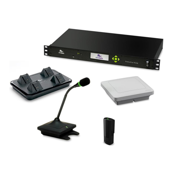
- Page 1 REVOLABS Executive Elite™ 2 Wireless Microphone System Installation and Operation Guide Models: 01-ELITEEXEC2 03-ELITEEXEC2-EU 03-ELITEEXEC2-JP...
- Page 2 © 2016 REVOLABS, INC. All rights reserved. No part of this document may be reproduced in any form or by any means without express written permission from Revolabs, Inc. Product specifications are subject to change without notice. R e v o l a b s E x e c u t i v e E l i t e I n s t a l l a t i o n a n d O p e r a t i o n G u i d e 0 1 - E X E C E L I T E 2 G U I D E - E N S E P T E M B E R 2 0 1 6 ( R e v 1 .
-
Page 3: Table Of Contents
Contents Contents ..............................3 Introduction ............................5 Safety and General Information ....................... 6 FCC Notice to Users ............................6 Industry Canada Notice to Users ......................... 7 For Body Worn Operation ..........................7 Professional Installation Recommended ....................7 Notice to Customers in Australia ......................... 8 Restricted use with certain medical devices .................. - Page 4 The Elite Wearable Wireless Microphones ..................71 The Elite Omni-Directional Wireless Tabletop Boundary Microphones ........74 The Elite Directional Wireless Tabletop Boundary Microphones ..........76 The Elite Wireless 6 inch and 12 inch Wireless Gooseneck Tabletop Microphones ..... 78 Elite Wireless XLR Adapter ........................80 The Elite Wireless TA4 (mini XLR) Adapter for lapel and ear-set microphones ....
-
Page 5: Introduction
Introduction Congratulations on your purchase of the Revolabs Executive Elite™ Wireless Microphone System. This system utilizes state of the art technology providing high bandwidth audio and enabling clear, reliable, untethered audio capture for your applications. Please read this documentation carefully and follow the instructions before... -
Page 6: Safety And General Information
Users are not permitted to make changes or modify the equipment in any way. Changes or modifications not expressly approved by Revolabs, Inc. could void your authority to operate this equipment under Federal Communications Commission’s rules. -
Page 7: Industry Canada Notice To Users
: (1) l'appareil ne doit pas produire de brouillage, et (2) l'utilisateur de l'appareil doit accepter tout brouillage radioélectrique subi, même si le brouillage est susceptible d'en compromettre le fonctionnement. IC: 6455A-01EXEC4 Revolabs Executive 2 Channel Base Station IC: 6455A-01EXECMIC Revolabs Executive Tabletop Microphone IC: 6455A-01EXECMICWR... -
Page 8: Notice To Customers In Australia
Notice to Customers in Australia 1. Do not use in areas where there are explosive hazards 2. Do not use in environments where there is a danger of ignition of flammable gasses. Restricted use with certain medical devices Hearing Aids Some devices may interfere with some hearing aids. -
Page 9: Notice To European Customers
Elite Microphone, Wearable 03-ELITEMIC-XLR-EU Elite Microphone, XLR microphone adapter 03-ELITEMIC-TA4-EU Elite Microphone, TA4 microphone adapter Any unauthorized modification of the products voids this Declaration. For a copy of the original signed declaration of conformity, please contact Revolabs at the above address. -
Page 10: Weee Notification
According to the requirement of the WEEE legislation the following user information is provided to customers for all branded Revolabs products subject to the WEEE directive. “The symbol on the product or its packaging indicates that this product must not be disposed of with your other household waste. -
Page 11: Safety Warnings
Do not open the casings of any of the components of the Executive Elite system. Do not use any other accessories than Revolabs’ originals intended for use with this product. Use of non-original accessories may result in loss of performance, damage to the product, fire, electric shock or injury. -
Page 12: Glossary
(or none) from behind. The pickup pattern is in the shape of a Cardioid. Channel – Executive Elite 2 can handle 2 wireless microphones per base. For ease of use, each microphone is assigned a channel number as part of the pairing. - Page 13 Remote Antenna – The external transmission and reception device for the Executive Elite System. The remote Antenna is connected to the Executive Elite Base DSP unit using a point-to-point Cat 5e or Cat 6 connection. User Interface (UI) – An interactive display allowing product users to control the Executive Elite system.
-
Page 14: Components
Power cable, USB cable, network cable Euroblock connectors Documentation In addition, you might have bought one or more Revolabs Elite wireless microphones. Each microphone package will include: Revolabs Elite wireless microphone (different styles) Lanyard and over-the-ear speaker element (wearable microphone only) ... - Page 15 Equalization Noise cancellation The Revolabs Elite system provides some of these features as well. It is recommended to use either external or Revolabs audio control systems to change settings and adapt the audio to your exact needs. Best audio quality is easier to attain when only one system is used to adapt the audio.
- Page 16 Finally, you might have purchased additional components like the ceiling mount kit for the remote antenna receiver, or the cross-over adapter to install wireless tabletop microphones permanently or semi-permanently on your tables.
-
Page 17: Installation
Installation Base DSP Unit The Revolabs Executive Elite Base DSP Unit, shown below in front and rear panel views, provides the audio output of the wireless microphones and the management interfaces to administer the microphone system. Front View USB web access to local web user interface... - Page 18 The Revolabs Executive Elite Base DSP Unit is designed to be installed into a standard 19” AV rack using the attached rack ears. Screws are not provided.
-
Page 19: Remote Antenna Receiver
Remote Antenna Receiver The Remote Antenna Receiver consists of two pieces – the mounting plate and the Antenna housing. The Remote Antenna Receiver is installed similar to a wireless access point. Best locations are high on the wall or under the ceiling, facing into the room in which the microphones are located. - Page 20 Once the back plate is attached to the wall and the network wire is connected to the Remote Antenna Receiver and routed correctly, the Remote Antenna enclosure is attached to the back plate by slipping it from the top onto the two hooks, and then pressing the bottom back against the wall plate until the snap clicks in.
- Page 21 Antenna placement Best results are achieved when the antenna faces into the area where the microphones are used. Optimal placements for the Antenna are either below the ceiling in the middle of the room facing down, or high on a wall facing into the room. The antenna should not be placed flat, e.g.
-
Page 22: Connect Remote Antenna Receiver To Base Dsp Unit
Connect Remote Antenna Receiver to Base DSP Unit Connect the Remote Antenna Receiver with the Antenna output of the Base DSP Unit using a CAT 5e or Cat 6 cable. NOTE: This needs to be a, point to point connection between the two units. -
Page 23: System Set-Up
For additional system configuration instructions, see later sections describing the different user interfaces in this manual. Analog Audio The back panel of the Executive Elite 2 base unit provides two 3.5mm Euroblock inputs and two 3.5mm Euroblock outputs, providing access to the audio signal. -
Page 24: Front Panel User Interface
Front panel user interface The Front panel user interface is one of four interfaces available to manage an Executive Elite system. The others are the local web UI, the Cloud Server Web UI, and the CLI (room control) interface and are described later in this document. - Page 25 The VU screen shows the audio volume for each unmuted, linked microphone, as well as battery charge information. “Up” from the VU screen, the RF View home screen shows the radio signal strength as measured on the receiver for each microphone. “Down”...
- Page 26 further below. The factory preset password is 7386 (REVO on a telephone key- pad), and can be changed either through the Admin Settings menu on the front panel interface, or the System Configuration menu on the local Web UI. All three home screens are split into 3 sections, and each section shows a different type of information.
- Page 27 - RF Meters. The RF screen will display the strength of the transmission from any linked microphone as it is received by the base. Microphones experiencing interference or far away will have a lower RF. The second row displays battery information when seen on the VU and RF screens, using the following icons: - For a linked microphone, the battery level icon will show the charge level by the amount of black in the battery.
-
Page 28: Front Panel Menu Tree
Front Panel Menu Tree The menu tree is navigated by using the “Right” button to enter a menu, the “Left” button to leave a menu, and the “Up” and “Down” buttons to scroll between the options in the menu. With the “Enter” button a menu entry is selected –... - Page 29 System Information The first option in the Main Menu is System Information. System Information offers information on the Base DSP unit, the Remote Antenna Receiver, the Microphones, and the available network connections. None of the information in this menu and the submenus can be changed. Base Information 1.
- Page 30 150 – 300 feet away from the remote antenna receiver might also be seen by other Revolabs devices in the vicinity. We recommend testing with different RF settings and using the RF Spectrum Analyzer in the local web...
- Page 31 except in high RF environments as it allows the system to automatically reduce RF power when it is not required. In the Admin Settings menu the standard password used on the local web UI and the front panel can be changed. The user can also log-out of the front panel from here.
- Page 32 The High-Pass and Low-Pass filter menus manage audio filters for each microphone. High-Pass filters should be used in rooms that have high level of background noise from air conditioners, projectors, etc. Low-Pass filters should be used in applications and installations that do not support wide band audio to ensure that no unwanted side effects occur.
-
Page 33: Local Web Ui
Local Web UI The local Web UI allows managing an Executive Elite base DSP unit through a web browser. The local web UI can be accessed either through the IP network if the Executive Elite base DSP unit is connected to the LAN using an Ethernet cable, or through the USB connector in the front of the base DSP unit. - Page 34 Logon page Open a supported web browser on your Computer or laptop and type in the IP address of the Executive Elite Base DSP unit. Once the web browser connects to the Executive Elite base DSP unit, it will show the logon page, asking for the system password.
-
Page 35: First Time Usage
Selecting a different region than the region you are using the system in may void your right to use the system! If you are unsure about which region to select, please contact Revolabs support at support@revolabs.com. Click Next once you have provided the information on this page. -
Page 36: Monitor Page
provided, the Elite Base DSP unit establishes communication with the Cloud Server and adds its information to the system registry on the server. The Create New Account button will bring up a registration window to create a new account on the Cloud Server. Further details on this process are provided in the revoCloud section of this document. - Page 37 1 – Mute Lock Button – Enable or Disable mute from the microphone. 2 – Chairman Symbol – This Microphone is set as Chairman for its group. 3 – Individual Mute Button – Works like the microphone’s mute would, but through the Web UI.
- Page 38 Both the Monitor and Microphone Audio pages have a microphone control dropdown menu accessible from the microphone tables. To open the menu, hover over the desired microphone’s column and a black-on-white arrow button will appear in the upper right corner. Clicking the arrow opens the microphone control menu, allowing access to the following options: ...
-
Page 39: Microphone Audio Page
For XLR and TA4 adapters, an additional pre-gain stage is offered. The Revolabs microphones (omni-directional, directional, gooseneck, and wearable) are set to provide signals on the same level with a focus on providing the best signal to noise ratio with the lowest risk of clipping of audio. XLR and TA4 adapters’... -
Page 40: Audio Management
Filters High-Pass and Low-Pass filters are provided to adjust to room and application requirements. Use the High-Pass filter in rooms that have a high background noise in the low frequencies (air conditioning, lighting fixtures, etc.). The Low- Pass filter allows limiting high frequencies, based on the applications used. All filters are bi-quad filters, reducing the signal by 6dB per octave. - Page 41 The Manage group screen shows a list of the groups defined for this system on the left, and the currently active group on the right side. Pressing the “+” sign (1) in the top left of the right column will create a new group.
- Page 42 The “Unmute at Startup” checkbox (7) next to the Mute Type menu determines whether microphones start unmuted when linking to the base, or muted. Chairman microphones provide a separate level of control to one microphone in a group. Independent of the selected mute group behavior, the chairman microphone in any group can mute all other microphones in that group.
- Page 43 Microphone audio can either be Standard definition (SD), or High Definition (HD). HD audio provides double the bit rate for audio transfer over the wireless link per microphone. Back channel audio is audio delivered to a wearable microphone, an XLR adapter, or TA4 adapter.
- Page 44 System Information The System Information page provides information on the Executive Elite’s components. “General Info” displays the System Name, the serial number, and the base firmware version. The “Remote Antenna Receiver” section shows the antenna’s MAC Address, the DECT ID for the baseband (antenna), and the antenna firmware version. This section also includes information on whether the antenna is currently connected or not.
- Page 45 Even if Base Pairing is not locked, the front panel requires the password before allowing pairing of microphones. A clock tuning option might be available on some systems. It should remain set to Default unless advised by Revolabs technical support to change that setting.
- Page 46 Network Management On this page Network Information for the Executive Elite is organized for easy access and management. The DHCP section allows enabling or disabling DHCP on the Executive Elite base DSP. If DHCP is enabled, the Executive Elite base DSP will request an IP address from your DHCP server.
- Page 47 appeared, giving the static IP Address for the USB connection. Open a web browser and enter the IP Address, then log into the Web UI. Now you may correct any network settings to connect the executive Elite base to your IP network. Below the IP information is the USB IP table.
- Page 48 returning to the page and pressing the “Stop” button, but the information will be cleared from memory once the scan has been stopped and the page is redirected away from. To save the scan result, take a screenshot of the page before navigating away, and store it using your preferred image editing application.
- Page 49 The different RF power settings provide suggested ranges in feet and meters for the maximum distance between the remote antenna and the microphones. While distances are provided in the setting, obstructions in a room do impact the maximum possible distance. Please keep that in mind when selecting a RF power level and testing connectivity.
- Page 50 Administration The Administration menu allows administrator level system control. Under Logging, system logs can be downloaded for advanced system information. The dropdown menu can be used to choose the severity level of the messages that will be retrieved. Below that, system configuration settings can be exported and imported. Importing a configuration will overwrite all currently active settings in this Executive Elite System.
- Page 51 information is not deleted as part of the system reset. If a system was registered before, the cloud registration window will not open. Microphone pairing information is also not affected by restoring Factory Defaults, previously paired microphones are still paired to the system. If microphones are paired, the microphone pairing dialog will not open.
- Page 52 Factory Default Settings Web UI Page Feature Default Setting Mic Audio 0 dB Preamp Gain (XLR style microphones) Mic Audio 0 dB Input Signal Trim Mic Audio High-Pass filter - all microphones 110Hz Mic Audio Low-Pass filter - all microphones None Mic Audio EQ (4 bands) - all microphones...
- Page 53 Web UI Page Feature Default Setting Network Mgmt. <<empty>> Default Gateway Network Mgmt. <<empty>> DNS1 Network Mgmt. <<empty>> DNS2 Network Mgmt. 192.168.10.4 USB Static IP Address Network Mgmt. 255.255.255.0 USB Subnet Mask Network Mgmt. NTP Servers (4) 0.pool.ntp.org 1.pool.ntp.org 2.pool.ntp.org RF Power Automatic (on/off) RF Power...
- Page 54 revoCloud Access To use an Executive Elite through the Cloud Server, it first needs to be registered. If registration was not completed during the Initial Setup, it can be registered through the Online Access page. An unregistered Elite’s revoCloud Access page takes the same appearance as the registration request page in the Initial Setup wizard.
- Page 55 Software Upgrade The Software Upgrade page offers two different methods to upgrade the firmware of an Executive Elite system. 1. An Executive Elite system registered to the Cloud Server may use the “Check for Latest Version” button to search revoCloud for the most recent version of the product firmware available on the server.
-
Page 56: Revocloud
Elite and the Cloud server is restricted to system usage information, microphone and battery usage information, user access logging, system change logging, system logging, RF information, and system settings. No audio data is ever transported to or saved on the Revolabs cloud server. -
Page 57: Creating A Revocloud Account
Creating a revoCloud Account To create an account for use on the revoCloud Server, first navigate to the Cloud Support web page at cloudsupport.recolabs.com. The home page will provide a box for login information. Click on the “Create New Account” button in the upper right hand corner. -
Page 58: Revocloud Home
The link provided in the verification email will expire 24 hours after the email was sent, so please verify the account as soon as possible. Once you click on the link provided in the verification email, you will be forwarded to the revoCloud web page, where you will see the verification message. - Page 59 Their system name and status as online or offline will appear at all times. When an Elite is online, that device’s IP Address and firmware version will be shown. Cluster names do not apply to Executive Elite 2 channel systems. Under status, the revoCloud server will report if the current firmware version on each base is up to date and display the progress of upgrades that have been started using the cloud.
-
Page 60: System Information
System Information The System information page provides additional information on any specific Executive Elite system. Beside the IP address of the system and the firmware version running on the system, it will also display the base serial number, the MAC address of the IP connector, and the run-time since the last start. This page allows remote download of logs from the Executive Elite. -
Page 61: Serial Control Processor (Room Control Interface)
Serial Control Processor (Room Control Interface) The Executive Elite Base DSP is capable of being monitored and controlled via a control system. Communication can either be over the serial port of the Executive Elite, or over an IP connection. If several Executive Elite Base DSPs are part of an installation, each requires its own connection to the control system in order to communicate. - Page 62 The Command Interface of the Executive Elite has been expanded significantly with additional and new functionality. These commands will not work with Revolabs Executive HD systems. Channel #: The options for the <Channel#> portion of the serial strings are 1-2 since each Base station can only control its own 2 microphones.
- Page 63 The following table includes a number of the Elite’s commands. Both Executive HD legacy commands and new generation Executive Elite commands will work when programing for the Executive Elite. Please consult the Room Control API document available at http://www.revolabs.com/support/product-line/executive-elite for the complete list. Property/Action Command Format...
- Page 64 Property/Action Command Format Description Response chairmanmute set chairmanmute Configure the given val chairmanmute ch <channel channel's chairman ch <channel number> <0/1/2> mute state. number> <0/1/2> 0 - all unmuted, 1 – members muted, 2 - all muted get eq ch <channel Retrieve the four EQ get eq ch <channel number>...
- Page 65 Property/Action Command Format Description Response micstandbymode get micstandbymode Retrieve mic standby val micstandbymode ch <channel number> status, ch <channel channel number 1-2 or number> <0/1> micstandbymode set micstandbymode Set mic into standby val micstandbymode ch <channel number> mode, ch <channel <0/1/2>...
- Page 66 Property/Action Command Format Description Response preampgain get preampgain ch Retrieve the given val preampgain ch <channel number> channel's preamp gain. <channel number> <preamp gain> preampgain set preampgain ch Configure the given val preampgain ch <channel number> channel's preamp gain, <channel number> <preamp gain>...
- Page 67 Property/Action Command Format Description Response lock get lock ch <channel Retrieve Mic Lock for val lock ch <channel number> specified channel. number> <0/1> mute set mute ch <channel Mute or unmute val mute ch <channel number> <0/1> specified channel: number> <0/1> 0 - Unmute, 1 - Mute mute get mute ch <channel...
- Page 68 Notifications Notification Format Description status_change_battery notify status_change_battery Notify client the given ch<channel number> microphone's battery status <percentage> changes. status_change_mic notify status_change_mic Notify client the given ch<channel number> <status> microphone's status changed, 0 - off, 1 - on, 2 - standby, 3 - charging, 4 - out of range, 5 - not paired,...
-
Page 69: Firmware Updates
Web UI using an upgrade software bundle accessible from the computer connected to the Executive Elite system as described on page 55. Upgrade bundles are available on Revolabs website in the support section. Firmware upgrades upgrade all linked components on an Executive Elite system. -
Page 70: Microphones
Microphones Revolabs Executive Elite offers a wide variety of wireless microphones and adapters to use with the system: Revolabs Elite Wearable Wireless Microphone Revolabs Elite Omni-directional Tabletop Wireless Boundary Microphone Revolabs Elite Uni-directional Tabletop Wireless Boundary Microphone ... -
Page 71: The Elite Wearable Wireless Microphones
The Elite Wearable Wireless Microphones The Revolabs Elite Wearable Microphones, shown in the following figure, can be worn on the user’s shirt, lapel, blouse, or on a lanyard. They provide high quality full duplex audio between the users and the conferencing or audio system. - Page 72 To use the Elite Wearable Microphone: 1. Remove the microphone from the Charger Base. 2. Attach the microphone to clothing or to a lanyard, positioning the microphone just above the sternum or breastbone, within 6 - 12 inches (15 – 30cm) from the mouth. Make sure that the microphone is attached securely.
- Page 73 Adjusting the Volume on the Wearable Microphone Earpiece To change the volume on the Wearable microphone earpiece, use the dial on the earpiece wire. Turning the dial as shown in the figure will increase decrease the volume. Use the attached clothing clip to secure the earpiece wire.
-
Page 74: The Elite Omni-Directional Wireless Tabletop Boundary Microphones
The Elite Omni-Directional Wireless Tabletop Boundary Microphones The Elite Omni-directional Wireless Tabletop Boundary Microphones enable multiple conference attendees to use a single microphone. 1. Mute touch areas & LEDs — touch to mute, un-mute, or pair the microphone. LEDs provide visual status for mute, un-mute, and pairing. The omni-directional microphone provides four mute touch areas and status LEDs, one on each side of the microphone. - Page 75 To use the Elite Omni-Directional Tabletop Microphone: 1. Remove the microphone from the Charger Base. The microphone will automatically turn on. Based on settings in the Base DSP, the microphone will start either un-muted or muted, indicated by green or red blinking lights, respectively.
-
Page 76: The Elite Directional Wireless Tabletop Boundary Microphones
The Elite Directional Wireless Tabletop Boundary Microphones The Elite Directional Wireless Tabletop Boundary Microphone, shown below, is designed to provide optimum coverage when placed on a conference room table in front of one to three people. 1. Mute touch area — touch to mute, un-mute, or pair the microphone. The directional microphone provides one mute touch area on the edge closest to the speaker. - Page 77 To use the Elite Directional Tabletop Microphone: 1. Remove the microphone from the Charger Base. The microphone will automatically turn on. Based on settings in the Base DSP, the microphone will start either un-muted or muted, indicated by green or red blinking LEDs, respectively.
-
Page 78: The Elite Wireless 6 Inch And 12 Inch Wireless Gooseneck Tabletop Microphones
The Elite Wireless 6 inch and 12 inch Wireless Gooseneck Tabletop Microphones The Elite Wireless 6 inch and 12 inch Wireless Gooseneck Tabletop Microphones, shown below, are designed to provide optimum coverage when a personal microphone is being assigned for each participant in the meeting or panel. - Page 79 To use either of the Elite Gooseneck Tabletop Microphones: 1. Remove the microphone from the Charger Base. The microphone will automatically turn on. Based on settings in the Base DSP, the microphone will start either un-muted or muted, indicated by green or red blinking lights, respectively.
-
Page 80: Elite Wireless Xlr Adapter
3. Li-Ion rechargeable battery — can be taken out and replaced after opening the battery door. Replace batteries only with Revolabs approved rechargeable batteries. 4. Battery charge status LED — warns for low battery. When there is approximately 2 hours of talk time remaining, this LED will turn yellow. - Page 81 To use the Elite Wireless XLR Adapter: 1. Remove the wireless adapter from the Charger Base. 2. Attach a dynamic handheld microphone to the adapter, following safety precautions and user information provided with that microphone. 3. After positioning the microphone at the distance it will be used at, unmute it and go to the Microphone Management page of the Web UI.
-
Page 82: The Elite Wireless Ta4 (Mini Xlr) Adapter For Lapel And Ear-Set Microphones
3. Li-Ion rechargeable battery — can be taken out and replaced after opening the battery door. Replace batteries only with Revolabs approved rechargeable batteries. 4. Battery charge status LED — warns for low battery. When there is approximately 2 hours of talk time remaining, this LED will turn yellow. - Page 83 NOTE: Use only microphones compatible with the wiring of the TA4 adapter. NOTE: The TA4 adapter provides 2.7 volts of phantom power. To use the Elite Wireless TA4 (mini XLR) Adapter: 1. Remove the mini XLR Adapter from the Charger Base. 2.
-
Page 84: Batteries
Batteries Replace batteries in the microphones only with Revolabs approved batteries! The tabletop microphones require standard Nickel Metal Hydrate NiMH rechargeable batteries with a 1.2 V voltage and a charge capacity of at least 1900mAh. Example batteries following these specifications are Sony NHAAB4KN or Panasonic HHR-210AAB. - Page 85 show any activity on the channel LED and front panel LCD, and will be shown as “Not Paired” on the web interfaces. During pairing, the microphone LEDs and the channel LED on the front of the Base DSP Unit will stay solid red. Only one microphone can be paired to any single Base DSP channel at a time.
-
Page 86: Led Patterns
LED patterns The following table shows activities associated with the various states shown by microphone or adapter mute LEDs. Base DSP Station Equipment Use Microphone LED Meaning Channel LEDs Microphone in Solid yellow Battery Type Test Charger Base Solid red or red Charging in Progress, blinking depending on Tray LED... -
Page 87: Mute Groups
2 hour remaining talk time on tabletop microphones. Mute Groups With Executive Elite, Revolabs introduces a very flexible way to define microphone groups. The main reason for microphone groups is to define a common mute behavior between the microphones (therefore the name “Mute Groups”). - Page 88 all microphones in the group will unmute in these circumstances. If it is not selected, then all microphones in the group will start muted. Individual Mute A mute group that is set to “Individual Mute” allows each microphone to control its own mute behavior. Touching the mute area of one microphone will toggle that microphone between muted and unmuted state, but will not affect other microphones in the group.
- Page 89 area the first time, all microphones in the group, except the chairman microphone, will go into a mute state, and cannot be unmuted from any of the other microphones in the group. Touching the mute area of the chairman microphone again will put all microphones into mute, including the chairman microphone.
-
Page 90: Warranty
Revolabs, Inc. warrants this product to be free of manufacturing defects. Repair or replacement of any defective part or unit (at the discretion of the Seller) will be free of charge for the period defined in the Revolabs Professional Products Limited Warranty. -
Page 91: Open Source Software
Open Source Software The following table lists the open source software in the Executive Elite products and the respective licenses under which these software packages are used. The different software licenses and license templates can be found on the internet at the following addresses (January 2014): License Type Web address GNU GPLv1... - Page 92 4.6.3 GNU LGPLv2.1 Tecla library 1.6.2 Free Software License C CGI library GNU GPLv2 jQuery 1.10.2 Strophe.js 1.0.2 cURL 7.33.0 OpenLLDP 0.4alpha GNU GPLv2 Source code for these open source software packages can be obtained by contacting Revolabs at support@revolabs.com.
-
Page 93: Troubleshooting
Troubleshooting Accessing the Web UI through the Front Panel USB If the network settings are configured incorrectly it can cause an Executive Elite system to become disconnected from the network, making access to the Web UI over the LAN impossible. However, the Web UI can still be accessed from the USB port on the front panel of the Elite. -
Page 94: Technical Support
Technical Support If you are experiencing technical problems or if you have questions about the operation, configuration or troubleshooting of any Revolabs product, please email support@revolabs.com or call 1-800-326-1088. -
Page 95: Specifications
Specifications Product Dimensions Component Subtype/Subcomponent Dimensions Weight Base DSP Unit 17.25 x 8 x 1.75 in 6.5 lbs 43.03 x 20.32 x 4.42 cm 2.95 kg Monochrome graphic display 216 x 64 pixels 2.8 x 0.8 in 71 x 21 cm Remote Antenna 6.8 x 6.8 x 2 in 16 oz. -
Page 96: Microphone Polar Patterns
Microphone Polar Patterns Elite Omni-Directional Wireless Tabletop Microphone : Elite Directional Wireless Tabletop Microphone:... -
Page 97: Index
Index Adjusting the Volume, 73 Microphones, 71 Ferrite, 22 Pairing, 84 Input Connectors, 23 Polar Patterns, 96 Safety Information, 6 Microphone Charging port, 71, 80, 82 System Components Base Station, 14 Earpiece Jack, 71, 80, 82 LED Display, 71, 80, 82 Microphone Charger Base, 14 Wireless Boundary Microphone, 74, 76 Mute Button, 71, 80, 82... - Page 98 R e v o l a b s E x e c u t i v e E l i t e I n s t a l l a t i o n a n d O p e r a t i o n G u i d e 0 1 - E X E C E L I T E 2 G U I D E - E N S E P T E M B E R 2 0 1 6 ( R e v 1 .
Need help?
Do you have a question about the Executive Elite 2 and is the answer not in the manual?
Questions and answers